
Subscribe to Our Youtube Channel
Summary of Contents for Wormald 08451
- Page 1 WORMALD FirePro Aerosol System Operation and Maintenance Manual Model 08451 Rev 2.1...
-
Page 2: Table Of Contents
Contents Introduction ................. 3 General Information ............. 3 How Does it Work ..............3 In Case of Fire ..............3 Components List ................4 Design Considerations ..............5 Power Supply Input.............. 5 Agent Released Input ............5 Siren/Strobe Output ............. 5 Discharge Output .............. -
Page 3: Introduction
Introduction General Information The FirePro FP-08451 Fire Control Panel is a combined detection and extinguishant system, and is compliant for use in both marine (AMSA NSCV) and vehicle installations (AS5062). The FIP (fire indicator panel) incorporates: 2x Detection circuits; 1x Extinguishing Discharge circuit;... -
Page 4: Components List
Components List 2x DP-3000 Deutsch Plug 3 Pin M/F, c/w heatshrink 4x DP-2000 Deutsch Plug 3 Pin M/F, c/w heatshrink FP-08451 2x FP-08950 End-of-line Plug 22kΩ (Detection) Fire Control Panel Detection and extinguishant End-of-line Diode 1N4004 (Siren/Strobe) control system End-of-Line Resistor 3k3Ω (Discharge) Operator’s Manual... -
Page 5: Design Considerations
Design Considerations Power Supply Input The FP-08451 Fire Control Panel provide a single power supply input that is compatible with 12 / 24vDC. If adequate power is not supplied, the LEDs will not be illuminated, and the control panel will not operate. The main power supply should be connected directly to a battery or power source, not through a distribution board. -
Page 6: Circuit 1 Alarm Output
It is necessary to complete all wiring and any programming of the detection mode prior to mounting the panel. Dimensions and relevant clearances for installing the FP-08451 Control Panel are below. A Dash Mount Bracket (P/N FP-08451B) is also available and may be used if the minimum clearances cannot be met. -
Page 7: Cabling Requirements
Cabling Requirements When constructing extension leads the supplied Deutsch Plugs must be used to ensure water- proof connections are made throughout the installation. 1. Cut cable to required length and strip outer insulation to approximately 25-30mm. 2. Strip inner insulation to approximately 6mm and using a Deutsch Crimping tool, fix pins to the exposed ends of the cable, including the earth where applicable. -
Page 8: Installation
access and should be used to minimise the required extension leads, and to bypass obstacles. Installation FirePro generators must remain disconnected until system is completed and fire control panel is no longer in a fault or alarm condition. The FirePro Test Module (P/N FP-08800) can be used to take the panel out of a fault condition. - Page 9 2. Agent Released Circuit: The Thermal Fuse Coupling (P/N FP-08825) should be screwed into the thermal port on one of the installed FirePro generators and connected to the control panel. 3. Siren/Strobe Circuit: Mount the siren/strobe (P/N FP-08940) in a location where it is visible and audible in all points with the risk area and connect to the “Siren”...
- Page 10 The Siren & Shutdown Module allows for programming of the delay prior to shutting down equipment and for the relay to be set to either normally open or normally closed Note: The Siren/Strobe or end-of-line diode must be connected for the relay to operate. Delay Timer Switch Mode Relay State Switch...
- Page 11 5. Circuit 2 Alarm Circuit: This circuit is ALARM ONLY and will only operate the siren/strobe. Connections for detection and manual actuator are the same as Circuit 1 Alarm. If detection is not used, the supplied end-of-line plugs (marked green) must be connected to the Circuit 2 Alarm output.
- Page 12 6. Discharge Circuit: This circuit should remain disconnected until all other circuits are connected. The control panel must not be in an alarm/fault condition when the FirePro generators are connected, as this may cause an accidental discharge. A Test Module (P/N FP-08800) should be connected to take the control panel out of fault condition and for any commissioning.
-
Page 13: Wiring Diagram
Wiring Diagram Page | 13... -
Page 14: Programming
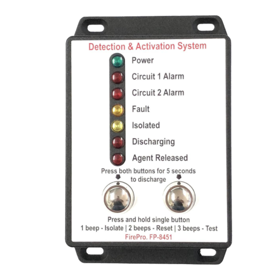
Note: If a Discharge Delay Module (P/N FP-08850) is installed, panel must be programmed for extended discharge. Operation LED Indicators The FP-08451 Control Panel uses LED indicators to notify the operator of the condition of the control panel and each of the monitored circuits. If an LED is illuminated, it indicates the following: Circuit... -
Page 15: Reset Function
Reset Function To reset the control panel, press and hold Mode Switch 1 until 2 beeps are heard. Following a reset, the control panel will automatically isolate. To restore the control panel to normal operation, press Mode Switch 1 and ensure the “Isolated” LED turns off. Note: The control panel cannot be reset if the activation sequence has been initiated. -
Page 16: Commissioning And Test Procedure
Commissioning and Test Procedure Commissioning should be performed when the fire control panel is not in an alarm/fault condition. Note: No personnel should be in the risk area until the fire system is fully isolated. Six Monthly Test Procedure: Isolate the control panel (see 7.2 Isolate Function) and disconnect the any installed FirePro aerosol generators. -
Page 17: Servicing And Maintenance
Discharge Testing from External Devices : Each detection and manual actuator device connected to must be tested individually. Perform an automatic discharge test by activating the detectors or manual actuators. Following the activation sequence ensure the Test Module has operated. Isolate the panel to silence the alarm. -
Page 18: Semi-Annual / Annual Service Schedule
Procedure. Troubleshooting The FP-08451 Control Panel provides a comprehensive fault monitoring system that will detect any open-circuit in the Circuit 1 Alarm Output, Circuit 2 Alarm Output, Siren/Strobe Output, Discharge Output and Agent Released Input and any malfunctions of the control panel’s internal components. -
Page 19: Specifications
Specifications General Dimensions 148L x 84W x 35D mm Material Diecast Aluminium, UV Tolerant Ingress Protection IP65 Operating Temperature -40 to 85 degrees Celsius Fault Monitoring – External Circuit 1 Alarm – Open/Closed Circuit 2 Alarm – Open/Closed Siren/Strobe – Open/Closed Discharge –... -
Page 20: Rfi Environments
RFI Environments The control panel’s circuit arrangement provides a number of layers of electronic protection designed to minimise the effects of electromagnetic emissions and prevent accidental discharges of the suppression system. Shielded, fire rated cable (FP-09500) is required to be used throughout every installation to protect the fire system from electromagnetic emissions. -
Page 21: Vehicle And Mobile Plant Installation Notes (As5062)
Vehicle and Mobile Plant Installation Notes (AS5062) For AS5062 vehicle installations, a risk assessment must be completed all equipment, and the design agreed upon by the installer and operators. The risk assessment should include identification of all fuel and ignition sources and these should be considered in the design of the fire system.
Need help?
Do you have a question about the 08451 and is the answer not in the manual?
Questions and answers