Table of Contents
Advertisement
Advertisement
Table of Contents
Troubleshooting

Subscribe to Our Youtube Channel
Related Manuals for Valleylab SurgiStat II

Summary of Contents for Valleylab SurgiStat II
- Page 1 Service Manual SurgiStat™ II Electrosurgical Generator...
- Page 2 The SurgiStat™ II was constructed with the highest quality components and was built in an ISO 9000 registered environment. In the unlikely event that your generator fails within one year of purchase date, Valleylab will warranty the product and effect factory repairs. Please refer to Section 8, Repair Policies and Procedures for what is covered, how long, and how to obtain a Return Authorization Number.
-
Page 3: Applicable Safety Standards
It is important that they read, understand, and follow the operating instructions supplied with this electrosurgical equipment. To promote the safe use of the SurgiStat II electrosurgical generator, please refer to the User’s Guide for standard operating precautions. -
Page 4: Table Of Contents
Preface ..................................ii Safety Precautions when Operating the Generator ..................iii Applicable Safety Standards ..........................iii Section 1. The SurgiStat II Electrosurgical Generator Functional Description ............................1-2 Unit Description ..............................1-3 Safety Precautions when Testing the Generator .................... 1-3 General Warnings, Cautions, and Notices ..................... - Page 5 Service Personnel Safety ............................5-2 Installation and Placement ..........................5-3 Functional (Operational) Checks ........................5-3 How to Set Up and Start the SurgiStat II Unit ..................5-3 How to Check the Patient Return Electrode Alarm Function ...............5-4 How to Check the Bipolar Mode (with Footswitch) ................5-4 How to Check the Monopolar Mode (with Footswitch) .................5-4...
- Page 6 Monopolar Select Circuit ..........................A-12 Main Printed Circuit Board ..........................A-13 Display Printed Circuit Boards ........................A-14 Relay Printed Circuit Board ..........................A-15 Front Panel Assembly ............................A-16 Back Panel Assembly ............................A-17 Final Assembly ..............................A-18 SurgiStat II Service Manual...
- Page 7 • Components and accessories • Safety Caution Read all warnings, cautions, and instructions provided with this generator before using. Read the instructions, warnings, and cautions provided with electrosurgical accessories before using. Specific instructions are not included in this manual. SurgiStat II Service Manual...
-
Page 8: Functional Description
Functional Description The SurgiStat II is a multipurpose electrosurgical generator for use in physician’s offices and surgi-centers. It provides unsurpassed performance, flexibility, reliability, and user convenience in one compact package. The SurgiStat II generator includes digital technology. This new technology is evident in the self-checking circuitry and error code readouts. -
Page 9: Unit Description
Unit Description The SurgiStat II electrosurgical generator is a self-contained unit, consisting of the main enclosure and power cord. The main components incorporated in the generator are: •... -
Page 10: Active Accessories
Set power levels to the lowest setting before testing an accessory. Notice During bipolar electrosurgery, do not activate the generator until the forceps have made contact with the patient. Product damage may occur. SurgiStat II Service Manual... -
Page 11: Fire/Explosion Hazards
Generator Electric Shock Hazards Warning Do not remove any covers or panels exposing the internal components. Refer to a Valleylab representative for service. Connect the generator power cord to a properly grounded receptacle. Do not use power plug adapters. Do not connect a wet power cord to the generator or to the wall receptacle. -
Page 12: Servicing
There are no internal user serviceable parts. For repairs, return the generator to Valleylab. Cleaning Notice Do not clean the generator with abrasive cleaning or disinfectant compounds, solvents, or other materials that could scratch the panels or damage the generator. SurgiStat II Service Manual... -
Page 13: Section 2. Controls, Indicators, And Receptacles
S E C T I O N Controls, Indicators, and Receptacles This section describes the front and rear panels, including all controls, indicators, receptacles, the fuse drawer, and ports. SurgiStat II Service Manual... -
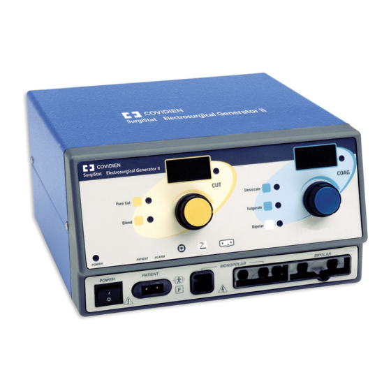
Page 14: Front Panel
Front Panel Figure 2-1.Layout of controls, indicators, and receptacles on the front panel SurgiStat II Service Manual... -
Page 15: Controls And Indicators Overview
Controls and Indicators Overview Users may control most SurgiStat II functions from the front panel. Each control is plainly marked and colored on the front panel for quick reference. Volume control and a footswitch connector are on the rear panel. -
Page 16: Cut And Blend Controls
Blend Selector When pressed, selects the Blend Cut and Blend Power mode. Control Dial Increases or decreases the Blend Indicator Cut or Blend power output in Illuminates when increments Blend mode is of one watt. selected. SurgiStat II Service Manual... -
Page 17: Coag And Bipolar Controls
Bipolar Selector When pressed, Coag and Bipolar Power Control Dial selects the Bipolar Increases or decreases the Coag or mode. Bipolar power output in increments of one watt. Bipolar Indicator Illuminates when Bipolar mode is selected. SurgiStat II Service Manual... -
Page 18: Indicators
Control Selector When pressed, Split-Plate Patient Return Single-Plate Patient Return switches between Electrode Indicator Electrode Indicator monopolar and Illuminates when the system Illuminates when the system bipolar foot control. detects a split-plate. detects a single-plate. SurgiStat II Service Manual... -
Page 19: Power Switch And Receptacles
Accepts standard three-pin on or off. handpieces. Connect Patient Return Electrode handswitching accessories. Receptacle Accepts a standard patient Monopolar Footswitching return electrode plug. Receptacle Accepts cables or adapters equipped with standard (Bovie #12) active plugs. Connect footswitching accessories. SurgiStat II Service Manual... -
Page 20: Rear Panel
Use only a Valleylab power consumption. monopolar footswitch with a SurgiStat II generator. Use of an incompatible footswith may cause unexpected output. SurgiStat II Service Manual... -
Page 21: Symbols On The Front Panel
Symbols Description Cut Controls Cut mode Blend mode Coag Controls Desiccate mode Fulgurate mode Bipolar mode Indicators Single-plate patient return electrode Split-plate patient return electrode Monopolar footswitch control Footswitch (on the selector button) Bipolar footswitch control SurgiStat II Service Manual... - Page 22 Power Switch and Handpiece Connectors Read instructions before use Type CF equipment Patient return electrode RF isolated – patient connections are isolated from earth at high frequency Caution – high voltage Monopolar output Bipolar output 2-10 SurgiStat II Service Manual...
- Page 23 Symbols on the Rear Panel Symbols on the Rear Panel Symbols Description Equipotential ground stud Nonionizing radiation Volume control Danger Explosion risk if used with flammable anesthetics Monopolar footswitch Read instructions before use SurgiStat II Service Manual 2-11...
- Page 24 2-12 SurgiStat II Service Manual...
-
Page 25: Section 3. Technical Specifications
All specifications are nominal and subject to change without notice. A specification referred to as “typical” is within ± 20% of a stated value at room temperature (25° C / 77° F) and a nominal input power voltage. SurgiStat II Service Manual... -
Page 26: Performance Characteristics
85° C (185° F) an alarm sounds, the system displays an error code, and the system disables output power. Dimensions and Weight Width 26 cm (10.25 in.) Depth 30.5 cm (12 in.) Height 15.2 cm (6 in.) Weight < 6.5 kg (< 14 lbs) SurgiStat II Service Manual... -
Page 27: Operating Parameters
IEC 60601-2-2. Activation Tone Volume (adjustable) 45 to 65 dBA Frequency Cut: 1 kHz Blend: 1 kHz Desiccation: 2 kHz Fulguration: 2 kHz Bipolar: 2 kHz Duration Continuous while the generator is activated SurgiStat II Service Manual... -
Page 28: Patient Return Electrode Sensing
Activation attempts during an alarm condition result in an audio alarm and the alarm indicator flashes. • When the alarm condition is resolved, the green single or split-plate indicator will illuminate. • The system measures the return electrode sensing current according to IEC 60601-1. SurgiStat II Service Manual... -
Page 29: Low Frequency (50-60 Hz) Leakage Current
< 150 mA current Standards and IEC Classifications The SurgiStat II generator meets all pertinent clauses of the IEC 60601-1 second edition and IEC 60601-2-2 third edition. Class I Equipment (IEC 60601-1) Accessible conductive parts cannot become live in the event of a basic insulation failure because of the way in which they are connected to the protective earth conductor. -
Page 30: Electromagnetic Interference
Voltage Transients (Emergency Generator Mains Transfer) The SurgiStat II generator operates in a safe manner when the transfer is made between line AC and an emergency generator voltage source. Electromagnetic Compatibility (IEC 60601-1-2 and... - Page 31 Guidance and manufacturer's declaration - electromagnetic emissions The SurgiStat II is intended for use in the electromagnetic environment specified below. The customer or the user of the SurgiStat II should ensure that it is used in such an environment. Emissions test...
- Page 32 Guidance and manufacturer's declaration - electromagnetic immunity The SurgiStat II is intended for use in the electromagnetic environment specified below. The customer or the user of the SurgiStat II should assure that it is used in such an environment. Immunity test...
- Page 33 To assess the electromagnetic environment due to fixed RF transmitters, an electromagnetic site survey should be considered. If the measured field strength in the location in which the SurgiStat II is used exceeds the applicable RF compliance level above, the SurgiStat II should be observed to verify normal operation. If abnormal performance is observed, additional measures may be necessary, such as reorienting or relocating the SurgiStat II.
- Page 34 Recommended separation distances between portable and mobile RF communication equipment and the SurgiStat II The SurgiStat II is intended for use in an electromagnetic environment in which radiated RF disturbances are controlled. The Customer or the user of the SurgiStat II can help prevent electromagnetic interferences by maintaining a minimum distance between portable and mobile RF communications equipment (transmitters) and the SurgiStat II as recommended below, according to the maximum output power of the communications equipment.
-
Page 35: Output Power Characteristics
Ω Bipolar 30 W @ 200 520 kHz ± 50 kHz 32 kHz ± 5 kHz 2.0 kV 6.9 ± 20% * An indication of a waveform’s ability to coagulate bleeders without a cutting effect SurgiStat II Service Manual 3-11... -
Page 36: Output Power Curves
Figure 3-1 . Output power vs. impedance for Pure Cut mode Load Resistance (ohms) Figure 3-2. Peak voltage vs. power setting for Pure Cut mode Output Power Setting (watts) 3-12 SurgiStat II Service Manual... - Page 37 Figure 3-3. Output power vs. generator settings for Pure Cut mode 100 105 110 115 120 Generator Setting Figure 3-4. Output power vs. impedance for Blend mode Load Resistance (ohms) SurgiStat II Service Manual 3-13...
- Page 38 Figure 3-5. Peak voltage vs. power setting for Blend mode Output Power Setting (watts) Figure 3-6. Output power vs. generator settings for Blend mode Generator Setting 3-14 SurgiStat II Service Manual...
- Page 39 These measurements were taken using short (< 0.5 meter) leads. Figure 3-7. Output power vs impedance for Desiccate mode Load Resistance (ohms) Figure 3-8. Peak voltage vs. power setting for Desiccate mode Output Power Setting (watts) SurgiStat II Service Manual 3-15...
- Page 40 Output power vs. generator settings for Desiccate mode 10 15 20 25 30 35 40 45 50 55 60 65 70 75 80 Generator Setting Figure 3-10. Output power vs. impedance for Fulgurate mode Load Resistance (ohms) 3-16 SurgiStat II Service Manual...
- Page 41 Figure 3-11. Peak voltage vs. power setting for Fulgurate mode Output Power Setting (watts) Figure 3-12. Output power vs. generator settings for Fulgurate mode Generator Setting SurgiStat II Service Manual 3-17...
- Page 42 Bipolar Curves Figure 3-13. Output power vs. impedance for Bipolar mode Load Resistance (ohms) Figure 3-14. Peak voltage vs. power setting for Bipolar mode Output Power Setting (watts) 3-18 SurgiStat II Service Manual...
- Page 43 Figure 3-15. Output power vs. generator settings for Bipolar mode Generator Setting SurgiStat II Service Manual 3-19...
-
Page 44: Reference Output Waveforms
Reference Output Waveforms The following figures are the output waveforms as viewed on an oscilloscope. Figure 3-16. Pure Cut mode waveform Figure 3-17. Blend mode waveform 3-20 SurgiStat II Service Manual... - Page 45 Figure 3-18. Desiccation mode waveform Figure 3-19. Fulguration mode waveform SurgiStat II Service Manual 3-21...
- Page 46 Figure 3-20. Bipolar mode waveform 3-22 SurgiStat II Service Manual...
-
Page 47: Section 4. Theory Of Operation
S E C T I O N Theory Of Operation This section includes the following information: • Block diagram • Functional overview of key circuits • System logic • Control signal inputs and outputs SurgiStat II Service Manual... -
Page 48: Block Diagram
The 8 VDC circuit supplies power for the RF drive circuit. This circuit turns on and off the power MOSFETS for the RF output power. • The 5 VDC circuit supplies power for the logic system and all of the displays and indicators. SurgiStat II Service Manual... -
Page 49: Dc Supply Check Circuit
System logic uses the audio circuit to generate activation tones and alarm tones. You can adjust volume for the activation tones from the back panel of the unit. Notice You cannot adjust alarm volume up or down. SurgiStat II Service Manual... -
Page 50: Patient Return Electrode Sensing Circuit
When you connect a single-plate patient return electrode to the unit, the pad sensing module will detect if the resistance is below 5 Ω. If it is, the SurgiStat II will display the green single-plate LED on the front of the unit. -
Page 51: Controls And Indicators
A system clock circuit, composed of an oscillator, provides the basic operating frequency of 5 MHz. The reset circuit provides a single pulse when you turn on the SurgiStat II generator. This pulse resets the field programmable gate array to ensure proper operation. -
Page 52: Surgistat Ii Control Signal Inputs And Outputs
SurgiStat II Control Signal Inputs and Outputs The following table lists the important input and output signals. From a troubleshooting standpoint, the absence (and presence) of these signals will help you isolate problems. Signal Name Description PAD_SNS_ERROR This is the input signal from the pad sense module that informs the system logic that a pad sensing error has occurred. - Page 53 A refers to the Cut button on the handpiece. A Colpitts oscillator located on the main board generates this signal. When an activation request occurs, this oscillator issues a logic 1 (5 VDC) signal. SurgiStat II Service Manual...
- Page 54 B refers to the Coag pedal on the footswitch. A Colpitts oscillator located on the main board generates this signal. When an activation request occurs, this oscillator issues a logic 1 (5 VDC) signal. SurgiStat II Service Manual...
-
Page 55: Section 5. Generator Operation
S E C T I O N Generator Operation This section covers the following topics: • Inspecting the generator and accessories • Service personnel safety • Installation and placement • Functional (operational) checks • Operating the unit SurgiStat II Service Manual... -
Page 56: Inspecting The Generator And Accessories
When using a smoke evacuator in conjunction with the electrosurgical generator, place the smoke evacuator a distance away from the generator. Set the generator’s volume control (on the rear panel) at a level that ensures all activation tones may be heard. SurgiStat II Service Manual... -
Page 57: Installation And Placement
Installation and Placement Place the SurgiStat II Electrosurgical Generator on any flat surface with a tilt angle of not more than 10 degrees. The unit relies on natural convection cooling. Do not block the rear vents. -
Page 58: How To Check The Patient Return Electrode Alarm Function
Bipolar Activation Indicator illuminates and that the system generates the coagulation activation tone. While activating the Coag mode, rotate the volume control over the full range to verify that the sound is audible throughout the range. SurgiStat II Service Manual... -
Page 59: How To Check The Monopolar Mode (With Handswitch)
Yellow or Cut pedal Footswitch Desiccate or Fulgurate Blue button Handswitching pencil modes Blue or Coag pedal Footswitch Bipolar Operation To activate ... Press this ... On this device ... Bipolar mode Blue (Coag) or yellow Footswitch (Cut) pedal SurgiStat II Service Manual... - Page 60 SurgiStat II Service Manual...
-
Page 61: Section 6. Maintenance
S E C T I O N Maintenance This section includes the following information: • Cleaning the unit • Performing periodic inspection • Replacing fuses SurgiStat II Service Manual... -
Page 62: Cleaning The Unit
• Damage to the power cord • Damage to the power cable receptacle • Obvious damage to the unit • Damage to any receptacle • Accumulation of lint or debris in or around the unit SurgiStat II Service Manual... -
Page 63: Replacing Fuses
Surg II-8 Surg II-J 110–120 V 220–240 V 90–110 V Amps 5.0 A 3.15 A 5.0 A Type Slow Blow Slow Blow Slow Blow Size 5 x 20 mm 5 x 20 mm 5 x 20 mm SurgiStat II Service Manual... - Page 64 SurgiStat II Service Manual...
-
Page 65: Section 7. Troubleshooting
S E C T I O N Troubleshooting This section includes error code descriptions and actions to take to resolve them. SurgiStat II Service Manual... -
Page 66: Recommended Equipment For Troubleshooting
If the system displayed an error code, take the appropriate action(s) to correct the error condition. Inspecting the Generator If the SurgiStat II malfunctions, check for obvious conditions that may have caused the problem. Check the generator for visible signs of physical damage. -
Page 67: Inspecting The Receptacles
Insert the footswitch connector into the footswitch receptacle. Check for a secure fit. Use only a Valleylab footswitch with the SurgiStat II generator. If the footswitch receptacle is damaged, contact your Valleylab Service Center. Check the bipolar receptacle on the front of the unit for obstruction or damage. -
Page 68: Understanding Error Codes And Audio Tones
Understanding Error Codes and Audio Tones The SurgiStat II Generator includes automatic, continual self-diagnostics. If the diagnostics detect an error, the system displays an error code, sounds an audible tone, and deactivates the output power. Any errors detected will shut down the RF output power. - Page 69 4. If alarm number reappears upon restarting the unit, record the number and call the Valleylab Service Center. E6 Delta check Internal pulse width measurement 1.
-
Page 70: Correcting Common Problems
Loose or disconnected cable between main board and display board Main board malfunction Display board malfunction Blank or confusing LED display Faulty ribbon cable between main Contact your Valleylab Service board and display board Center. Display board malfunction SurgiStat II Service Manual... - Page 71 RF output stage malfunction Footswitch will not activate output Malfunctioning or damaged footswitch Contact your Valleylab Service receptacle Center. Footswitch activation signal lost on main board Incompatible footswitch Use only a Valleylab footswitch with the SurgiStat II generator. SurgiStat II Service Manual...
- Page 72 Some manufacturers offer RF choke filters for use in monitor leads. The filters reduce interference when the generator is activated and minimize the potential for an electrosurgical burn at the site of the monitor electrode. SurgiStat II Service Manual...
- Page 73 Can occur during coag Use a lower power setting for the Fulgurate mode or select the Desiccate mode. Abnormal 50-60 Hz leakage currents Contact your Valleylab Service Center. SurgiStat II Service Manual...
- Page 74 7-10 SurgiStat II Service Manual...
-
Page 75: Section 8. Repair Policy And Procedures
S E C T I O N Repair Policy and Procedures This section contains the following information: • The manufacturer’s responsibility • Returning the generator for service SurgiStat II Service Manual... -
Page 76: Responsibility Of The Manufacturer
Returning the Generator for Service Before you return the generator, call your Valleylab representative for assistance. If instructed to send the generator to Valleylab, first obtain a Return Authorization Number. Then, clean the generator and ship it to Valleylab for service. -
Page 77: Clean The Generator
Return Authorization Number. Ship the generator, prepaid, to the Valleylab Service Center. Service Center For a complete list of service centers worldwide, please refer to the Valleylab website: http://www.valleylab.com/valleylab/international/service-world.html SurgiStat II Service Manual... - Page 78 SurgiStat II Service Manual...
-
Page 79: Section 9. Warranty
This warranty does not apply to any product, or part thereof, which has been repaired or altered outside Valleylab’s factory in a way so as, in Valleylab’s judgment, to affect its stability or reliability, or which has been subjected to misuse, neglect, or accident. - Page 80 Valleylab. Valleylab neither assumes nor authorizes any other person to assume for it any other liability in connection with the sale or use of any of Valleylab’s products. Notwithstanding any other provision herein or in any other document or communication, Valleylab’s liability with respect to this agreement and products...
-
Page 81: Section A. Board Drawings And Schematics
APPENDIX Board Drawings and Schematics This supplement contains the assembly drawings and schematics for the following printed circuit boards: • Control board • Display board • Footswitch board • Power Supply/RF board. SurgiStat II Service Manual... - Page 82 SurgiStat II Service Manual...
Need help?
Do you have a question about the SurgiStat II and is the answer not in the manual?
Questions and answers