
Related Manuals for Great Wall GW4D20

Summary of Contents for Great Wall GW4D20
- Page 1 长城内燃机 GREAT WALL ENGINES GW4D20/GW4D20B 型增压柴油发动机维修手册 MAINTENANCE MANUAL OF GW4D20/GW4D20B TURBOCHARGED DIESEL ENGINES 保定长城内燃机制造有限公司 编 Edited by Great Wall Baoding Internal Combustion Engine Manufacturing Company Limited...
- Page 2 MAINTENANCE MANUAL OF GW4D20/GW4D20B TURBOCHARGED DIESEL ENGINES Introduction This maintenance manual describes the primary technical data, troubleshooting, maintenance, disassembly and assembly, adjustment, repair and other related information of the GW4D20/GW4D20B turbocharged diesel engines so as to provide reference for the related maintenance personnel and repairman.
- Page 3 China IV Vehicle Exhaust Emission Standard. The GW4D20/GW4D20B diesel engine is mainly carried various kinds of LCV, SUV/MPV, compact cars, high-grade pickups produced by Great Wall Motor Company Limited and similar models from other auto manufacturers.
- Page 4 This maintenance manual should not be reprinted or published without the permission from our company. Our company reserves all copyrights that described in law, and reserves the rights of modification and explanation. Great Wall Baoding Internal Combustion Engine Manufacturing Company Limited Dec. 18, 2009 Great Wall Baoding Internal Combustion Engine...
-
Page 5: Table Of Contents
Reliability and Durability Index ....................18 Low Public Hazard Index ......................18 Section IV Engine Property Curves......................19 Section V Technical Data and Specifications of Engine ................21 Technical Parameters of Engine ....................21 Great Wall Baoding Internal Combustion Engine Manufacturing Company Limited... - Page 6 MAINTENANCE MANUAL OF GW4D20/GW4D20B TURBOCHARGED DIESEL ENGINES Various Temperature and Pressure Ranges of Engine ............. 23 Specifications of Main Engine Accessories ................24 Specifications of Main Parts of Fuel Supply System ..............25 Section VI Maintenance Standard for Engine ..................26 Tightening Torque of Main Fasteners of Engine ................
- Page 7 Difficulty in Starting the Diesel Engine at a Low Temperature ........... 91 Insufficient Power in the Diesel Engine ..................92 Excessive Fuel Consumption of Diesel Engine ................. 93 Abnormal Noise During the Diesel Engine Running ..............93 Great Wall Baoding Internal Combustion Engine Manufacturing Company Limited...
- Page 8 Section V Piston and connecting rod assembly ..................178 Section VI Engine oil pump assembly ....................196 Section VII Cylinder body assembly ...................... 201 Chapter V GW4D20 / GW4D20B Turbocharged Diesel Engine............215 Section I General ............................ 215 Section II Engine Assembly ........................216 Section III Engine Brackets ........................
- Page 9 Oil Filter ............................ 429 Engine Oil Pump ........................432 Oil Collector ..........................439 Oil Pan ............................. 442 Chapter IX Turbocharging System ..................... 446 Section I General ............................ 446 Turbocharging system composition ..................446 Great Wall Baoding Internal Combustion Engine Manufacturing Company Limited...
- Page 10 MAINTENANCE MANUAL OF GW4D20/GW4D20B TURBOCHARGED DIESEL ENGINES Turbocharger structure ......................446 Section II On-board Maintenance ......................449 Section III Inspection and Repair ......................454 Checking the working condition of the exhaust outlet ............. 454 Checking the working condition of the turbocharger ............... 455 Checking the axial clearance of the impeller shaft.
-
Page 11: Chapter I Introduction
Assembly sequence crankshaft Assembly in the sequence reverse to disassembly. Fig. 1-1-1 Disassembly / Assembly Schematic Diagram for Oil Pump Parts The repair procedure is introduced in the following sequence: Great Wall Baoding Internal Combustion Engine Manufacturing Company Limited... - Page 12 MAINTENANCE MANUAL OF GW4D20/GW4D20B TURBOCHARGED DIESEL ENGINES (1) The schematic diagram shows what to do and where to do it, see Fig. 1-1-2. (2) The title of the work task shows the content of repair. (3) Explain in detail how to carry out the work content and provide other technical information, such as specification and attention, note, etc., and the quantity and dimensions of fasteners.
- Page 13 Power: W, kW; Length: μm, mm, m, km; Rotating speed: r/min; Pressure, pressure strength: Pa, kPa, MPa; Temperature: ° C Volume: mL, L; Mass: g, kg; Electric current: A; Electric resistance: Ω, kΩ; Great Wall Baoding Internal Combustion Engine Manufacturing Company Limited...
-
Page 14: Section Ii Main Contents Of Civilized Production For Maintenance
MAINTENANCE MANUAL OF GW4D20/GW4D20B TURBOCHARGED DIESEL ENGINES Voltage: V; Plane angle: ° ; Noise: dB/A; Time: s, min, h. Section II Main Contents of Civilized Production for Maintenance Civilized production is aimed at creating a good producing condition and working environment to improve maintenance quality, ensure personnel and device security, and improve labor efficiency. -
Page 15: Section Iv Dress Security Requirements For Maintenance Personnel
(5) Norm of the working hour to accomplish the maintenance work. Section VI Identification Marks Serial number of the engine The serial number of GW4D20/GW4D20B turbocharged diesel engine is stamped on the left cylinder body, as shown in Fig. 1-6-1. -
Page 16: Section Vii General Repair Instructions
MAINTENANCE MANUAL OF GW4D20/GW4D20B TURBOCHARGED DIESEL ENGINES Section VII General Repair Instructions 1. When carrying out repair, use the baffle, seat and floor mat to keep the vehicle clean and intact and prevent damage. 2. During disassembly, keep parts in a proper order so as to facilitate reassembly. - Page 17 Fig. 1-7-6 Checking the Conductor Connector be replaced with new parts. 11.5 Never use an impact spanner to disassemble or mount a temperature sensor or other sensors which has specific torque requirements. Great Wall Baoding Internal Combustion Engine Manufacturing Company Limited...
-
Page 18: Section Viii Precautions For Maintenance Operation
MAINTENANCE MANUAL OF GW4D20/GW4D20B TURBOCHARGED DIESEL ENGINES Section VIII Precautions for Maintenance Operation If the vehicle is equipped with the mobile communication system, such as the two-way wireless communication equipment and cellular phone, the following precautions should be observed: (1) Install the communication antenna away from the ECU and sensors of automotive electronic system as far as possible. -
Page 19: Chapter Ii Technical Information Of Engine
(the intake and exhaust valve, valve Fig. 2-1-3 Valve Actuating Mechanism pin/clip, valve spring, spring seat, valve oil seal, etc.), transmission mechanism (the belt, pulley, intake/exhaust camshaft assembly, rocker arm, Great Wall Baoding Internal Combustion Engine Manufacturing Company Limited... -
Page 20: Turbocharging System
MAINTENANCE MANUAL OF GW4D20/GW4D20B TURBOCHARGED DIESEL ENGINES hydraulic lash adjuster, etc.), air filter, intake/exhaust pipelines, intake/exhaust manifolds, etc. The electric Cylinder head control EGR valve and EGR cooler contained in the intake/exhaust systems carry out the exhaust gas recirculation process, and effectively limit the No constituent in emissions. -
Page 21: Lubrication System
Starting motor given to their working conditions. Otherwise, the normal work of the diesel engine can not be ensured or serious Fig. 2-1-9 Startup Device damage to engine parts may be caused. Great Wall Baoding Internal Combustion Engine Manufacturing Company Limited... -
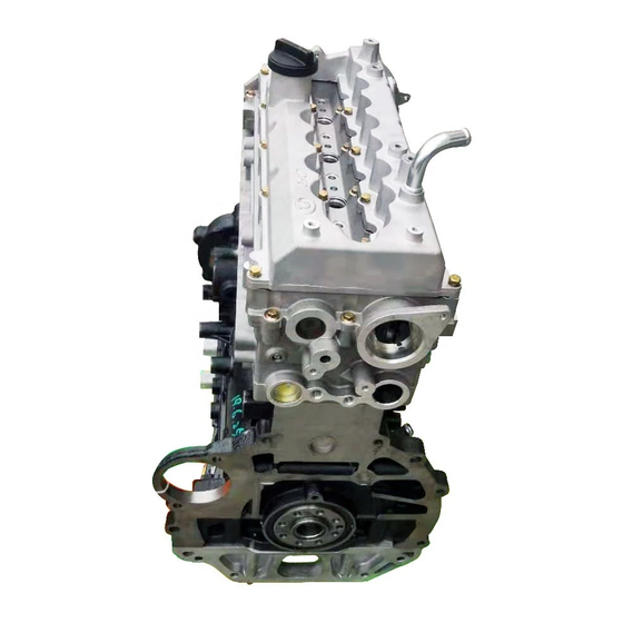
Page 22: Section Ii View Of Engine
MAINTENANCE MANUAL OF GW4D20/GW4D20B TURBOCHARGED DIESEL ENGINES Section II View of Engine 1. Front View of Engine For the front view of GW4D20 turbocharged diesel engine assembly, see Fig. 2-2-1. Fig. 2-2-1 Front View of GW4D20 Turbocharged Diesel Engine Assembly (Equipped with Delphi Common Rail System) 1-Accessory Tension Pulley Assembly;... -
Page 23: Rear View Of Engine
Chapter II Technical Information of Engine 2. Rear View of Engine For the rear view of GW4D20 turbocharged diesel engine assembly, see Fig. 2-2-2. Fig. 2-2-2 Rear View of GW4D20 Turbocharged Diesel Engine Assembly (Equipped with Delphi Common Rail System) 1-Clutch Assembly;... -
Page 24: Left View Of Engine
MAINTENANCE MANUAL OF GW4D20/GW4D20B TURBOCHARGED DIESEL ENGINES 3. Left View of Engine For the left view of GW4D20 turbocharged diesel engine assembly, see Fig. 2-3-3. Fig. 2-2-3 Left View of GW4D20 Turbocharged Diesel Engine Assembly (Equipped with Delphi Common Rail System) 1-Refrigeration Compressor Assembly;... -
Page 25: Right View Of Engine
Chapter II Technical Information of Engine 4. Right View of Engine For the right view of GW4D20 turbocharged diesel engine assembly, see Fig. 2-2-4. Fig. 2-2-3 Right View of GW4D20 Turbocharged Diesel Engine Assembly (Equipped with Delphi Common Rail System) 1-Engine Lifting Hook;... -
Page 26: Vertical View Of Engine
MAINTENANCE MANUAL OF GW4D20/GW4D20B TURBOCHARGED DIESEL ENGINES 5. Vertical View of Engine For the vertical view of GW4D20 turbocharged diesel engine assembly, see Fig. 2-2-5. Fig. 2-2-3 Vertical View of GW4D20 Turbocharged Diesel Engine Assembly (Equipped with Delphi Common Rail System) 1-Fuel Injector Assembly;... -
Page 27: Section Iii Main Performance Indexes Of Engine
Attention has always been taking for the reduction of fuel consumption since it has great significance for decreasing engine application costs, promoting rational use of resources, improving the ecological environment, etc., and the fuel consumption is decreasing year by year. Great Wall Baoding Internal Combustion Engine Manufacturing Company Limited... -
Page 28: Reliability And Durability Index
MAINTENANCE MANUAL OF GW4D20/GW4D20B TURBOCHARGED DIESEL ENGINES 3. Reliability and Durability Index 3.1 Reliability Reliability of the engine means the engine can work continuously and its normal working ability is not influenced by malfunctions under the designed working condition. In China, the reliability of engine is normally represented by non-stop malfunction times, stop malfunction times and number of major parts and minor parts replaced during the warranty period (or insurance period). -
Page 29: Section Iv Engine Property Curves
Chapter II Technical Information of Engine Section IV Engine Property Curves For the power, torque property curves of the GW4D20 turbocharged diesel engine, see Fig. 2-4-1. Rotation speed (r/min) Fig. 2-4-1 Power, Torque Property Curves of GW4D20 Turbocharged Diesel Engine ——Fuel consumption rate (g/kW·... - Page 30 MAINTENANCE MANUAL OF GW4D20/GW4D20B TURBOCHARGED DIESEL ENGINES Rotation speed (r/min) Fig. 2-4-2 Power, Torque Property Curves of GW4D20B Turbocharged Diesel Engine ——Fuel consumption rate (g/kW· h); G ——Fuel consumption volume (kg/h); P ——Effective power ——Effective torque (N· m) (kW); M...
-
Page 31: Section V Technical Data And Specifications Of Engine
Chapter II Technical Information of Engine Section V Technical Data and Specifications of Engine 1. Technical Parameters of Engine For the main technical parameters of the GW4D20/GW4D20B turbocharged diesel engine, see Table 2-5-1. Table 2-5-1 Main Technical Parameters of GW4D20/GW4D20B Turbocharged Diesel Engine... - Page 32 MAINTENANCE MANUAL OF GW4D20/GW4D20B TURBOCHARGED DIESEL ENGINES (Continued) Item Unit Technical Parameter Lubrication Mode Pressure and splash combination type Fuel Grade API CI-4 Engine Oil Capacity ≤ 0.3% (rated power point) Oil/fuel Consumption Ratio Cooling Mode Forced circulating water cooling...
-
Page 33: Various Temperature And Pressure Ranges Of Engine
Heated to 800 ℃ in 8 s Heater Plug Heating time 2. Various Temperature and Pressure Ranges of Engine For various temperature and pressure ranges of GW4D20/GW4D20B turbocharged diesel engine, see Table 2-5-3. Table 2-5-3 Various Temperature and Pressure Ranges of GW4D20/GW4D20B Turbocharged Diesel Engine... -
Page 34: Specifications Of Main Engine Accessories
MAINTENANCE MANUAL OF GW4D20/GW4D20B TURBOCHARGED DIESEL ENGINES 3. Specifications of Main Engine Accessories For the specifications of main accessories of GW4D20/GW4D20B turbocharged diesel engine, see Table 2-5-4. Table 2-5-4 Specifications of Main Accessories of GW4D20/GW4D20B Turbocharged Diesel Engine Accessory System and Name... -
Page 35: Specifications Of Main Parts Of Fuel Supply System
Chapter II Technical Information of Engine 4. Specifications of Main Parts of Fuel Supply System For the specifications of main parts of GW4D20/GW4D20B turbocharged diesel engine fuel supply system, see Table 2-5-5. Table 2-5-5 Specifications of Main Parts of GW4D20/GW4D20B Turbocharged Diesel Engine Fuel... -
Page 36: Section Vi Maintenance Standard For Engine
1. Tightening Torque of Main Fasteners of Engine For the tightening torque of main fasteners of GW4D20/GW4D20B turbocharged diesel engine, see Table 2-6-1. Table 2-6-1 Tightening Torque of Main Fasteners of GW4D20/GW4D20B Turbocharged Diesel... - Page 37 25± 3 drain screw plug) Hexagonal flange Exhaust manifold Q32008F32 30± 3 ——cylinder head face nut For the tightening torque standards for general fasteners of GW4D20/GW4D20B turbocharged diesel engine, see Table 2-6-2. Great Wall Baoding Internal Combustion Engine Manufacturing Company Limited...
-
Page 38: Fit Clearance Of Main Parts Of Engine
518-1999 518-1999 2. Fit Clearance of Main Parts of Engine For the fit clearances of main parts of GW4D20/GW4D20B turbocharged diesel engine, see Table 2-6-3. Table 2-6-3 Fit Clearances of Main Parts of GW4D20/GW4D20B Turbocharged Diesel Engine. Sequence Name of Fit Clearance of Parts... - Page 39 Journal (1, 2, 3) =1-3 Yellow (1) 0.020~0.046 mm None (2) 0.024~0.044 mm =5-6 Blue (3) 0.022~0.048 mm For the matching selection by group of cylinder Bores and pistons, see table 2-6-6. Great Wall Baoding Internal Combustion Engine Manufacturing Company Limited...
- Page 40 0.071~0.090 mm 0.070 For positions for daubing or injecting lubricating oil on assembly parts of GW4D20/GW4D20B turbocharged diesel engine, see Table 2-6-7. Table 2-6-7 Positions for Daubing or Injecting Lubricating oil on Engine Assembly Parts (Mobil Oil Corp., API CI-4 Plus diesel engine oil)
- Page 41 Anaerobic fixative for TONSAN 1608 sealing fixative body and cylinder head cylindrical parts for bowl-shaped plugs For the oil filling capacity of GW4D20/GW4D20B turbocharged diesel engine, see Table 2-6-9. Table 2-6-9 Lubricating oil Capacity of Engine Item Capacity Recommended Lubricating oil Grades...
-
Page 42: Section Vii Running-In Of Engine
1. Preparation Before Running-in 1.1 Operators should read the Use and Maintenance Manual for GW4D20/GW4D20B Turbocharged Diesel Engine carefully to be familiar with the structure, performance, operation and maintenance methods of the engine. -
Page 43: Precautions For Running-In
5.1 Keep a normal coolant temperature (80 ℃ ~ 90 ℃; the temperature can be 105 ℃ when a pressure water tank is used) and a normal oil pressure (≥ 0.4 MPa). 5.2 Keep the vehicle at a normal driving speed and prevent high speed driving. Great Wall Baoding Internal Combustion Engine Manufacturing Company Limited... -
Page 44: Section Viii Technical Maintenance For Engine
50000 ~ 100000 km, or upon user’s own decision in accordance with the working condition of diesel engine. For the maintenance cycle of the GW4D20/GW4D20B turbocharged diesel engine, please refer to Table 2-8-1. According to technical maintenance requirements, the maintenance may be carried out in the procedure of filling, cleaning, washing, adjusting, lubricating, repairing or replacing after check-up. - Page 45 Chapter II Technical Information of Engine Table 2-8-1 Maintenance Cycle for GW4D20/GW4D20B Turbocharged Diesel Engine Maintenance First level Second level Third level Remarks cycle Daily maintenance maintenance maintenance technical 4000 ~ 4000 ~ 4000 ~ 100,000 maintenance Maintenance 5000 km...
- Page 46 MAINTENANCE MANUAL OF GW4D20/GW4D20B TURBOCHARGED DIESEL ENGINES when replacing the belt, replace the tension pulley Tension pulley, Replace the subassembly, accessory wedge Check, tension pulley accessory wedge idle wheel and maintain after changing idle wheel and flat flat idle wheel...
-
Page 47: Technical Maintenance Contents
Warning: the electrolyte is corrosive and must not be splashed in eyes, on skin and clothes; clean it with fresh water immediately if it is splashed on above mentioned places. Great Wall Baoding Internal Combustion Engine Manufacturing Company Limited... - Page 48 MAINTENANCE MANUAL OF GW4D20/GW4D20B TURBOCHARGED DIESEL ENGINES (3) Check if there is oil, water, air or electricity leakage, turbocharger remove them if the ―four leakages‖ are found. (4) Check if various accessory devices are fastened. (5) After starting the engine, listen if the engine is running...
- Page 49 Fig. 2-8-9 Checking the exhaust manifold pipe gasket 2.5 Seasonal Technical Maintenance (1) It is recommended to replace the antifreeze/antirust fluid in the diesel engine cooling system as the winter is coming, see Fig. 2-8-11. Great Wall Baoding Internal Combustion Engine Manufacturing Company Limited...
-
Page 50: Technical Maintenance For Air Cleaner
MAINTENANCE MANUAL OF GW4D20/GW4D20B TURBOCHARGED DIESEL ENGINES (2) In winter, a suitable fuel (vehicle diesel) grade should be chosen according to the ambient temperature. (3) In winter, the lubricating oil for winter use in the lubricating system should be used. -
Page 51: Technical Maintenance For Oil Supply System
System 4.1. Technical Maintenance for Fuel Filter The function of fuel filter is to filter the impurities in diesel so as to prevent precision accessories in oil supply system from wear. Great Wall Baoding Internal Combustion Engine Manufacturing Company Limited... - Page 52 MAINTENANCE MANUAL OF GW4D20/GW4D20B TURBOCHARGED DIESEL ENGINES The fuel filter is mounted on the low pressure fuel circuit. Fuel inlet The diesel enters the filter and the mechanical impurities Fuel outlet are eliminated by the filter core. The filtered diesel enters...
-
Page 53: Technical Maintenance For Fuel Lubrication System
Figure 2-8-19 Checking the oil level with an There are upper/lower scale marks on the dipstick to oil dipstick help to check the oil level (see Fig. 2-8-20), the oil level Great Wall Baoding Internal Combustion Engine Manufacturing Company Limited... - Page 54 MAINTENANCE MANUAL OF GW4D20/GW4D20B TURBOCHARGED DIESEL ENGINES should not be below the lower scale mark, because it will result in that the oil pump cannot pump up the oil. It is also not appropriate that the oil level is higher than the...
- Page 55 (6) Start the diesel engine after the mounting, and check if the oil filter leaks. Then stop the diesel engine, check the lubricating oil level with a dipstick, add lubricating oil if necessary. Great Wall Baoding Internal Combustion Engine Manufacturing Company Limited...
-
Page 56: Technical Maintenance For Cooling System
MAINTENANCE MANUAL OF GW4D20/GW4D20B TURBOCHARGED DIESEL ENGINES Caution: (1) The rotary oil filter is disposable and is not allowed to be reused. (2) The oil filter should be replaced regularly in accordance with technical maintenance requirements. Special tool Special attention should be paid to the rubber sealing... - Page 57 Send it to a professional service station for check and maintenance in time if users do not have required conditions. Great Wall Baoding Internal Combustion Engine Manufacturing Company Limited...
-
Page 58: Additional Maintenance In Severe Driving Conditions
(2) The third level maintenance should be carried out indoors in order to prevent from dust. (3) For some complex maintenances or adjustments with higher technology requirements, send them to the professionals or Great Wall Baoding Combustion Engine Manufacturing Company. Section IX Repair Process for Diesel Engine 1. -
Page 59: Engine Handover And Repair Class Identification
When the vehicle is handed over, the owner and the staff from the service station work together to check the engine and to define the repair class. Information about the engine completeness and the general technical conditions should be filled in the handover sheet. Great Wall Baoding Internal Combustion Engine Manufacturing Company Limited... -
Page 60: Exterior Washing For The Engine
MAINTENANCE MANUAL OF GW4D20/GW4D20B TURBOCHARGED DIESEL ENGINES 2.2 Engine repair class The engine (vehicle) repair class is divided into overhaul, minor repair, maintenance and adjustment. 2.2.1 Overhaul The overhaul is the regular repair. During the overhaul, thoroughly check the engine (vehicle), and repair or replace the parts which are overly worn. -
Page 61: Section X Technical Requirements For Engine Removal And Reinstallation
1.1 The spare parts assembled should be those manufactured according to the drawings and technical conditions of GW4D20/GW4D20B turbocharged diesel engines approved by our company, and their materials, Repair the abnormal metallurgical... - Page 62 MAINTENANCE MANUAL OF GW4D20/GW4D20B TURBOCHARGED DIESEL ENGINES into the assembling location should be clean in order to maximally reduce impurities and dust brought into the location. 1.5 The assembling sequence should comply with the flow process and abide by the rule of ―from interior to exterior‖...
-
Page 63: General Technical Requirements For Removal
First, make clear the structures and characteristics of Fig. 2-10-5 Understanding the structure of GW4D20/GW4D20B turbocharged diesel engines, and the diesel engine make clear the removing procedure and method to avoid damage of spare parts. See Fig. 2-10-5. -
Page 64: Section Xi Special Tools And Instruments For Repair
MAINTENANCE MANUAL OF GW4D20/GW4D20B TURBOCHARGED DIESEL ENGINES Section XI Special Tools and Instruments for Repair When adjusting, testing, maintaining, repairing, removing, assembling the diesel engine, you may use special tools, instruments and devices in order to conveniently and quickly remove and reinstall the spare parts, examine the spare parts and define malfunctions,. - Page 65 KTS 650 diagnostic 0-986-612-901 See Page 86 apparatus The special tools listed in this manual are for reference only; users may purchase appropriate special tools in accordance with maintenance requirements. Great Wall Baoding Internal Combustion Engine Manufacturing Company Limited...
-
Page 66: Section Xii Repair Operation For Engine
MAINTENANCE MANUAL OF GW4D20/GW4D20B TURBOCHARGED DIESEL ENGINES Section XII Repair Operation for Engine Attention: The general repair operation should be done by qualified maintenance personnel. 1. Model Mark Engine number The diesel engine number is printed on the central front of left side of cylinder body, as shown in Fig.2-12-1. -
Page 67: Lubrication System
(8) Check the oil level in the engine lubrication system with an engine oil dipstick (see Fig.2-12-7), add oil till it reaches the specified level if necessary. Great Wall Baoding Internal Combustion Engine Manufacturing Company Limited... -
Page 68: Fuel System
MAINTENANCE MANUAL OF GW4D20/GW4D20B TURBOCHARGED DIESEL ENGINES It is recommended to use APlCl-4 or above diesel engine oil produced by Mobil Oil Corporation. Start the diesel engine and check if the lubrication Engine oil system works properly, and check if there is leakage in dipstick the oil filter. -
Page 69: Cooling System
It is recommended to use the coolant produced by our company. When replenishing coolant, never add any Fig. 2-12-13 Mixing ratio of coolant antirust additive or other additives into the cooling Great Wall Baoding Internal Combustion Engine Manufacturing Company Limited... - Page 70 MAINTENANCE MANUAL OF GW4D20/GW4D20B TURBOCHARGED DIESEL ENGINES system. Because they may be incompatible with the coolant or engine parts. See Fig. 2-12-13 to determine the correct mixing ratio of coolant and water. 5.2 Check for the cooling system Mount the radiator tester on the radiator. Apply the test pressure to the cooling system to check leakage.
-
Page 71: Engine Control
Idling speed of the diesel engine Fig. 2-12-19 Adjusting the idling speed 750 r/min ± 50 r/min Great Wall Baoding Internal Combustion Engine Manufacturing Company Limited... -
Page 72: Quick Start-Up System
MAINTENANCE MANUAL OF GW4D20/GW4D20B TURBOCHARGED DIESEL ENGINES 6.2 Adjustment to the throttle control cable (1) Loosen the throttle wiring bracket bolt. (2) Check if the idling control button is located in the idling position of diesel engine. (3) Make sure that the throttle connecting rod is completely closed, and then tighten the control cable to remove looseness. -
Page 73: Section Xiii Engine Parts And Tightening Torques
Chapter II Technical Information of Engine Section XIII Engine Parts and Tightening Torques 1. Engine Bracket Mounting Assembly Cylinder body assembly Cylinder body assembly Great Wall Baoding Internal Combustion Engine Manufacturing Company Limited... -
Page 74: Cylinder Body Mounting Assembly
MAINTENANCE MANUAL OF GW4D20/GW4D20B TURBOCHARGED DIESEL ENGINES 2. Cylinder Body Mounting Assembly Cylinder body component Sectional view of the upper cylinder body Great Wall Baoding Internal Combustion Engine Manufacturing Company Limited... -
Page 75: Cylinder Body Component
Chapter II Technical Information of Engine 3. Cylinder Body Component Upper cylinder body Crankshaft Lower cylinder body Step 1 Step 2 Step 3 Turn for 90° again Turn for 90° Great Wall Baoding Internal Combustion Engine Manufacturing Company Limited... -
Page 76: Cylinder Head Mounting Assembly --1
MAINTENANCE MANUAL OF GW4D20/GW4D20B TURBOCHARGED DIESEL ENGINES 4. Cylinder Head Mounting Assembly ——1 DELPHI cylinder cover assembly BOSCH or XINFENG cylinder cover assembly BOSCH or XINFENG cylinder head Great Wall Baoding Internal Combustion Engine Manufacturing Company Limited... -
Page 77: Cylinder Head Mounting Assembly --2
Chapter II Technical Information of Engine 5. Cylinder Head Mounting Assembly ——2 DELPHI camshaft bearing cap BOSCH or XINFENG camshaft bearing cap Cylinder head assembly Great Wall Baoding Internal Combustion Engine Manufacturing Company Limited... -
Page 78: Cylinder Head Mounting Assembly --3
MAINTENANCE MANUAL OF GW4D20/GW4D20B TURBOCHARGED DIESEL ENGINES 6. Cylinder Head Mounting Assembly ——3 Step 1 Step 2 Turn for 90° ± 5° Step 3 Turn for 120° ± 5° Step 1 Step 2 Turn for 90° ± 5° Step 3 Turn for 120°... -
Page 79: Piston Connecting Rod Mounting Assembly
Chapter II Technical Information of Engine 7. Piston Connecting Rod Mounting Assembly Step 1 Step 2 Turn for 90° ± 5° Great Wall Baoding Internal Combustion Engine Manufacturing Company Limited... -
Page 80: Crankshaft Flywheel And Clutch Mounting Assembly
MAINTENANCE MANUAL OF GW4D20/GW4D20B TURBOCHARGED DIESEL ENGINES 8. Crankshaft Flywheel and Clutch Mounting Assembly Great Wall Baoding Internal Combustion Engine Manufacturing Company Limited... -
Page 81: Air Intake And Exhaust Systems Mounting Assembly --1
Chapter II Technical Information of Engine 9. Air Intake and Exhaust Systems Mounting Assembly ——1 DELPHI air intake manifold pipe BOSCH or XINFENG air intake manifold pipe Great Wall Baoding Internal Combustion Engine Manufacturing Company Limited... -
Page 82: Air Intake And Exhaust Systems Mounting Assembly --2
MAINTENANCE MANUAL OF GW4D20/GW4D20B TURBOCHARGED DIESEL ENGINES 10. Air Intake and Exhaust Systems Mounting Assembly ——2 Cylinder head mounting assembly Air intake manifold pipe Great Wall Baoding Internal Combustion Engine Manufacturing Company Limited... -
Page 83: Oil Pan And Engine Oil Collector Mounting Assembly
Chapter II Technical Information of Engine 11. Oil Pan and Engine Oil Collector Mounting Assembly Great Wall Baoding Internal Combustion Engine Manufacturing Company Limited... -
Page 84: Engine Oil Pump Mounting Assembly
MAINTENANCE MANUAL OF GW4D20/GW4D20B TURBOCHARGED DIESEL ENGINES 12. Engine Oil Pump Mounting Assembly Cylinder body assembly Engine oil pump mounting assembly Great Wall Baoding Internal Combustion Engine Manufacturing Company Limited... -
Page 85: Engine Oil Cooler And Cooling Pipelines Mounting Assembly
Chapter II Technical Information of Engine 13. Engine Oil Cooler and Cooling Pipelines Mounting Assembly Upper cylinder body Engine oil filter mounting assembly Engine oil cooler mounting assembly Great Wall Baoding Internal Combustion Engine Manufacturing Company Limited... -
Page 86: Timing Mechanism Mounting Assembly --1
MAINTENANCE MANUAL OF GW4D20/GW4D20B TURBOCHARGED DIESEL ENGINES 14. Timing Mechanism Mounting Assembly ——1 Great Wall Baoding Internal Combustion Engine Manufacturing Company Limited... -
Page 87: Timing Mechanism Mounting Assembly --2
Chapter II Technical Information of Engine 15. Timing Mechanism Mounting Assembly ——2 BOSCH or XINFENG crankshaft timing belt pulley component DELPHI crankshaft timing belt pulley component Great Wall Baoding Internal Combustion Engine Manufacturing Company Limited... -
Page 88: Fuel Supply System Mounting Assembly --1①
MAINTENANCE MANUAL OF GW4D20/GW4D20B TURBOCHARGED DIESEL ENGINES 16. Fuel Supply System Mounting Assembly ——1 ① Note: ① DELPHI fuel supply system mounting assembly. Great Wall Baoding Internal Combustion Engine Manufacturing Company Limited... -
Page 89: Fuel Supply System Mounting Assembly --2①
Chapter II Technical Information of Engine ① 17. Fuel Supply System Mounting Assembly ——2 Note: ① BOSCH fuel supply system mounting assembly. Great Wall Baoding Internal Combustion Engine Manufacturing Company Limited... -
Page 90: Fuel Supply System Mounting Assembly --3①
MAINTENANCE MANUAL OF GW4D20/GW4D20B TURBOCHARGED DIESEL ENGINES ① 18. Fuel Supply System Mounting Assembly ——3 Note: ① XINFENG fuel supply system mounting assembly. Great Wall Baoding Internal Combustion Engine Manufacturing Company Limited... -
Page 91: Turbocharger Mounting Assembly --1①
Chapter II Technical Information of Engine ① 19. Turbocharger Mounting Assembly ——1 Note: ① VGT turbocharger mounting assembly. Great Wall Baoding Internal Combustion Engine Manufacturing Company Limited... -
Page 92: Turbocharger Mounting Assembly --2①
MAINTENANCE MANUAL OF GW4D20/GW4D20B TURBOCHARGED DIESEL ENGINES ① 20. Turbocharger Mounting Assembly ——2 Note: ① WGT turbocharger mounting assembly. Great Wall Baoding Internal Combustion Engine Manufacturing Company Limited... -
Page 93: Egr System Mounting Assembly
Chapter II Technical Information of Engine 21. EGR System Mounting Assembly Air intake manifold pipe Cylinder head Great Wall Baoding Internal Combustion Engine Manufacturing Company Limited... -
Page 94: Electronic Control System Sensor
MAINTENANCE MANUAL OF GW4D20/GW4D20B TURBOCHARGED DIESEL ENGINES 22. Electronic Control System Sensor Cylinder body assembly Crankshaft position sensor (XINFENG) Great Wall Baoding Internal Combustion Engine Manufacturing Company Limited... -
Page 95: Generator Mounting Assembly
Chapter II Technical Information of Engine 23. Generator Mounting Assembly Cylinder body assembly Generator belt Great Wall Baoding Internal Combustion Engine Manufacturing Company Limited... -
Page 96: Throttle Mounting Assembly
MAINTENANCE MANUAL OF GW4D20/GW4D20B TURBOCHARGED DIESEL ENGINES 24. Throttle Mounting Assembly Exported AT vehicle model Air intake manifold pipe Common vehicle model Air intake manifold pipe Great Wall Baoding Internal Combustion Engine Manufacturing Company Limited... -
Page 97: Thermostat And Water Pump Mounting Assembly
Chapter II Technical Information of Engine 25. Thermostat and Water Pump Mounting Assembly Cylinder body assembly Thermostat shield Cylinder body assembly Great Wall Baoding Internal Combustion Engine Manufacturing Company Limited... -
Page 98: Engine And Compressor Mounting Assembly
MAINTENANCE MANUAL OF GW4D20/GW4D20B TURBOCHARGED DIESEL ENGINES 26. Engine and Compressor Mounting Assembly Cylinder body assembly Cylinder body assembly Lower cylinder body Great Wall Baoding Internal Combustion Engine Manufacturing Company Limited... -
Page 99: Vacuum Pump And Steering Pump Mounting Assembly
Chapter II Technical Information of Engine 27. Vacuum Pump and Steering Pump Mounting Assembly Cylinder head assembly Cylinder body assembly Great Wall Baoding Internal Combustion Engine Manufacturing Company Limited... -
Page 100: Chapter Iii Malfunction Diagnosis And Troubleshooting
MAINTENANCE MANUAL OF GW4D20/GW4D20B TURBOCHARGED DIESEL ENGINES Chapter III Malfunction Diagnosis and Troubleshooting Section I Troubleshooting When the diesel engine works, due to wearing, distortion, usage and improper maintenance and so on, the technical condition of each part will worsen gradually; when some technical indicators surpass the tolerant limits, it indicates that the diesel engine is malfunctioning. -
Page 101: Failure To Start The Diesel Engine
(the engine oil above temperature, or the starting resistive APl CI – 4 of Mobil Oil Corp. is recommended) torque of diesel engine increasing. Great Wall Baoding Internal Combustion Engine Manufacturing Company Limited... -
Page 102: Insufficient Power In The Diesel Engine
MAINTENANCE MANUAL OF GW4D20/GW4D20B TURBOCHARGED DIESEL ENGINES Select the low temperature storage battery Failing to select the storage battery as with the capacity higher than 100 Ah according Battery required in severe cold areas; the battery to the working temperature of the diesel capacity lower than 100 Ah. -
Page 103: Excessive Fuel Consumption Of Diesel Engine
First, identify the abnormal noise, whether the knocking noise is due to abnormal erupting or due to abnormal running of parts within the engine body. Then check and diagnose the noise source according Great Wall Baoding Internal Combustion Engine Manufacturing Company Limited... - Page 104 MAINTENANCE MANUAL OF GW4D20/GW4D20B TURBOCHARGED DIESEL ENGINES to the noise characteristics and combining the structure principle. Attention: It is strictly prohibited that the engine continues operating in case of abnormal noise, stop running immediately if abnormal noise appears, check and eliminate the malfunction, then continue to work.
-
Page 105: Abnormal Noise From Diesel Engine
(which makes the exhaust light blue or light grey). When the exhaust pipe of the diesel engine emits black, blue or white smoke, it means that the technical status of the diesel engine is abnormal. Great Wall Baoding Internal Combustion Engine Manufacturing Company Limited... -
Page 106: Heavy Oil Consumption And Low Pressure Of The Diesel Engine Lubrication System
MAINTENANCE MANUAL OF GW4D20/GW4D20B TURBOCHARGED DIESEL ENGINES Phenomenon and Cause of Malfunction Troubleshooting (1) Overload of the diesel engine (1) Reduce the diesel engine load to the rated operating range. (2) See Chapter 11 for troubleshooting the oil (2) Malfunction of the oil supply supply system. - Page 107 Wash or repair it. Engine oil cylinder body and the cylinder head unable to Wash or repair it. reach the (2) Blockage of the rocker arm valve system upper oil hole Great Wall Baoding Internal Combustion Engine Manufacturing Company Limited...
-
Page 108: Abnormal Coolant Temperature, Lack Of Coolant In The Diesel Engine Cooling System
MAINTENANCE MANUAL OF GW4D20/GW4D20B TURBOCHARGED DIESEL ENGINES 9. Abnormal Coolant Temperature, Lack of Coolant in the Diesel Engine Cooling System Phenomenon and Cause of Malfunction Troubleshooting (1) Low coolant level (lack of coolant) (1) Refill coolant, check the cooling system for leakage and repair it if necessary. -
Page 109: Malfunction Of The Diesel Engine Turbocharging System
High fuel (2) Bad performance of the turbocharger (2) Wash, adjust replace consumption turbocharger. (3) Wear of the piston ring (3) Check or replace the piston ring. Great Wall Baoding Internal Combustion Engine Manufacturing Company Limited... -
Page 110: Malfunction Of The Diesel Engine Oil Supply System
MAINTENANCE MANUAL OF GW4D20/GW4D20B TURBOCHARGED DIESEL ENGINES (continued) Phenomenon and Cause of Malfunction Troubleshooting Wear damage (1) Replace the turbocharger assembly. turbocharger sealing ring (2) Overhaul. leakage (3) Overhaul the oil inlet pipe, oil return hose; compressor blades High oil replace the gasket. - Page 111 (5) Air left in the fuel system (5) Exhaust air from the fuel system. (6) Preheat system (6) Check the preheat system. Coolant temperature sensor (7) Check the coolant temperature sensor Great Wall Baoding Internal Combustion Engine Manufacturing Company Limited...
- Page 112 MAINTENANCE MANUAL OF GW4D20/GW4D20B TURBOCHARGED DIESEL ENGINES (winter) (winter). (8) Blockage or overlow temperature (8) Check the low pressure oil circuit. of the low pressure oil circuit (9) Check the high pressure oil circuit, high (9) overlow pressure of the high...
-
Page 113: Diesel Engine Wobble During Idling
Exhaust air and water from the system fuel system. Low pressure oil circuit Blockage or overlow pressure of Check, repair or replace the the low pressure oil circuit; oil corresponding parts fuel Great Wall Baoding Internal Combustion Engine Manufacturing Company Limited... -
Page 114: Diesel Engine Running At A High Idle Speed
MAINTENANCE MANUAL OF GW4D20/GW4D20B TURBOCHARGED DIESEL ENGINES leakage or blockage of the fuel system. system Fuel injector Bad performance or blockage of Replace fuel injector. the fuel injector Whenever the fuel injector is replaced, it is required to input the 13C code of the new fuel injector into the ECU again. -
Page 115: Working Starter But Non-Working Diesel Engine
Unable remove anti-theft Overhaul the anti-theft system. Anti-theft system protection Main relay Damage of the main relay Replace the main relay. Great Wall Baoding Internal Combustion Engine Manufacturing Company Limited... -
Page 116: Diesel Engine Rotating But Unable To Be Started
MAINTENANCE MANUAL OF GW4D20/GW4D20B TURBOCHARGED DIESEL ENGINES Fuse cable Looseness or bad contact of the fuse Clean and fasten the fuse cable. connector cable Rotation speed Damage of the rotation speed sensor Replace the rotation speed sensor. sensor fuel fuel... -
Page 117: Difficulty In Starting Due To Malfunction In The Quick Start-Up System
The glow plug indicator lamp is (1) Start the diesel engine, set (1) Replace the quick start-up the starting switch from ―ST‖ to on for 3.5 s. timer. ―ON‖, and the glow plug relay Great Wall Baoding Internal Combustion Engine Manufacturing Company Limited... -
Page 118: No Power Generation, Undercharge Or Overhigh Charging Current Of Generator
MAINTENANCE MANUAL OF GW4D20/GW4D20B TURBOCHARGED DIESEL ENGINES Checking Item and Position Cause Troubleshooting should be on for at least 14 s, otherwise quick start-up timer may be damaged. (2) Set the starting switch from ―OFF‖ to ―ON‖ and the glow plug... -
Page 119: Insufficient Capacity, Difficulty In Starting Or Overhigh Self Discharge Of The Storage Battery
(4) Remove the storage battery in the sequence of earthing wire, positive pole wire, storage battery baffle plate and then the storage battery. Installation the storage battery in the opposite sequence. Great Wall Baoding Internal Combustion Engine Manufacturing Company Limited... -
Page 120: Section Ii Malfunction Diagnosis
MAINTENANCE MANUAL OF GW4D20/GW4D20B TURBOCHARGED DIESEL ENGINES Section II Malfunction Diagnosis 1. Start-up system malfunction diagnosis Check whether the storage battery is normal and then conduct the diagnosis as follows. Non-working starter Check the storage battery. Charging failure or out of... - Page 121 Repair it Connection malfunction Open circuit or connection of the starting switch malfunction between starting switch storage battery Replace the Repair it starting switch Great Wall Baoding Internal Combustion Engine Manufacturing Company Limited...
- Page 122 MAINTENANCE MANUAL OF GW4D20/GW4D20B TURBOCHARGED DIESEL ENGINES The electromagnetic switch doesn’t work after the starting switch is turned to the ―ST‖ position Turn the starting switch to the ―ST‖ Position and check whether there is a voltage at the electromagnetic switch terminal ―S‖...
- Page 123 All the wires except the wires above should be disconnected The contact of electromagnetic switch Replace the starter switch is melted and cannot move or the return spring is broken or damaged Replace electromagnetic switch Great Wall Baoding Internal Combustion Engine Manufacturing Company Limited...
-
Page 124: Turbocharging System Malfunction Diagnosis
MAINTENANCE MANUAL OF GW4D20/GW4D20B TURBOCHARGED DIESEL ENGINES 2. Turbocharging System Malfunction Diagnosis Malfunction diagnosis: ① The malfunction diagnosis means to find out the position and cause of the turbocharging system malfunction and clear the malfunction accordingly.② Don’t replace the turbocharger before clearing the malfunction.③ The malfunction diagnosis method and procedure for the turbocharged engine are the same as those of the non-turbocharged engine.④... - Page 125 Attention: If a turbocharger is of a proper appearance, the rotor can work properly and the blade has no interference with its housing, it means the turbocharger is in good condition. 3. Turbocharger Oil Leakage Malfunction Diagnosis Great Wall Baoding Internal Combustion Engine Manufacturing Company Limited...
- Page 126 MAINTENANCE MANUAL OF GW4D20/GW4D20B TURBOCHARGED DIESEL ENGINES The seal of turbocharger is achieved by the higher air pressure established in the housings at both ends of the turbocharger than the air pressure in the intermediate body fuel return chamber (equal to the air pressure in the crankcase).
- Page 127 (4) Air leakage from the connecting pipe between the gas compressor housing exhaust port and the engine air intake pipe. (5) Air leakage from the connector between the turbo housing intake port and the exhaust pipe exhaust port Great Wall Baoding Internal Combustion Engine Manufacturing Company Limited...
- Page 128 MAINTENANCE MANUAL OF GW4D20/GW4D20B TURBOCHARGED DIESEL ENGINES (6) Long idle speed time. (7) Overhigh pressure or oil level in the crankcase or blockage of crankcase vent. (8) Overhigh engine lower blow-by. Improper diagnosis method for oil leakage: Remove the connecting pipe between the gas compressor housing exhaust port and the engine air intake port, and then start the engine and check whether there are oil drops injected from the gas compressor housing exhaust port with air flow.
-
Page 129: Chapter Iv Mechanical System
Air intake/exhaust camshaft assembly ○ Hydraulic clearance adjuster and rocker arm ○ Cylinder head Installation procedure Install them in the opposite order of removal. Fig. 4-1-1 Disassembly and reassembly sequences for cylinder head Great Wall Baoding Internal Combustion Engine Manufacturing Company Limited... - Page 130 MAINTENANCE MANUAL OF GW4D20/GW4D20B TURBOCHARGED DIESEL ENGINES Disassembly precautions: (1) Before disassembly, you should fully make yourself be familiar with the structural principle and disassembly sequence of parts to prevent parts damage. (2) During disassembly, the parts of the valve component...
- Page 131 (3) Take out the packing from the sealing groove of Cylinder head cylinder cover. cover packing Check the cylinder head packing and replace it if Fig. 4-1-6 Removing the cylinder head cover there is any damage or deformation. assembly Great Wall Baoding Internal Combustion Engine Manufacturing Company Limited...
- Page 132 MAINTENANCE MANUAL OF GW4D20/GW4D20B TURBOCHARGED DIESEL ENGINES Disassembling the fuel injector assembly ⑦ (1) Removing the fuel injector harness plug: Pull out the harness plug self-locking device, and then remove the fuel injector harness plug. (2) Remove the fastening bolts of fuel injector ballast.
- Page 133 Fig. 4-1-12. (3) The removed glow plugs should be placed separately, and be protected against contamination or being bumped. Heater plug Fig. 4-1-12 Removing the glow plug Great Wall Baoding Internal Combustion Engine Manufacturing Company Limited...
- Page 134 MAINTENANCE MANUAL OF GW4D20/GW4D20B TURBOCHARGED DIESEL ENGINES Disassembling the vacuum pump assembly ○ (1) Pull out the vacuum connecting hose from the Cylinder head vacuum pump. (2) Remove the 3 hexagon flange bolts (M6×20) connecting the vacuum pump to cylinder head ring flange.
- Page 135 ——Incorrect installation. ——Looseness or warp. ——Insufficient tightening torque for cylinder head bolt. ——Warped surface of cylinder body. (2) Check whether there is any damage or elongation of Great Wall Baoding Internal Combustion Engine Manufacturing Company Limited...
- Page 136 MAINTENANCE MANUAL OF GW4D20/GW4D20B TURBOCHARGED DIESEL ENGINES threads of the cylinder head bolts (see Fig. 4-1-19), and any damage caused by incorrect tool usage. Attention: Any suspicious bolt should be replaced. (3) Check whether there is any crack in the cylinder head, especially in the area between valve seats and at the exhaust port.
- Page 137 (7) Fix the cylinder head to the cylinder body, and align the 10 screw holes, then fit and screw the 10 cylinder head bolts (M11×1.5×162) according to specified sequences. See Fig. 4-1-24. Tightening torque for cylinder head fastening bolt Great Wall Baoding Internal Combustion Engine Manufacturing Company Limited...
- Page 138 MAINTENANCE MANUAL OF GW4D20/GW4D20B TURBOCHARGED DIESEL ENGINES Step 1 Step 2 Step 3 50 N· m± 3 N· m Turn for 90° Turn further for 120° Lubrication Attention: Check the cylinder head bolt before installation and replace it when there is any deformation, elongation, thread sliding or other faults.
- Page 139 (3) Fix the vacuum coupling hose to the vacuum pump. assembly There should be no deflection or misplacement after installation. Tightening torque for vacuum pump fastening bolt 9 N· m± 3 N· m Great Wall Baoding Internal Combustion Engine Manufacturing Company Limited...
- Page 140 MAINTENANCE MANUAL OF GW4D20/GW4D20B TURBOCHARGED DIESEL ENGINES Reinstalling the glow plug assembly ○ (1) Screw the 4 glow plugs into the corresponding Cylinder head mounting hole of the cylinder head air intake end, and tighten the glow plugs using a hexagon socket head spanner to the specified torque.
- Page 141 EGR condenser, and the 2 hexagon flange bolts (M18×20) connecting the air intake pipe and EGR condenser, using specified torques, as shown in Fig. Great Wall Baoding Internal Combustion Engine Manufacturing Company Limited...
- Page 142 MAINTENANCE MANUAL OF GW4D20/GW4D20B TURBOCHARGED DIESEL ENGINES 4-1-36. Water outlet pipe Air intake pipe Tightening torque for EGR system fastening bolt EGR condenser 23N· m± 3N· m Reinstalling the fuel injector assembly ⑦ Exhaust (1) Tighten the supporting bolts of the fuel injector ballast manifold pipe by using the required torque onto the cylinder head.
- Page 143 (3) Install the fuel return hose support and clamp. Make sure the fuel return hose is sealed properly without leakage after installation. Fig. 4-1-41 Installing the fuel inlet pipe and return hose of fuel injector Great Wall Baoding Internal Combustion Engine Manufacturing Company Limited...
- Page 144 MAINTENANCE MANUAL OF GW4D20/GW4D20B TURBOCHARGED DIESEL ENGINES Reinstalling the fuel inlet pipes of fuel injector and fuel rail ③ (1) Remove the dust cap from the upper end of the fuel Timing mark injector. Install the fuel inlet pipe for the fuel injector, and tighten evenly the pipe connectors at both ends of the 4 fuel pipe as per the specified torque, as shown in Fig.
- Page 145 Tightening torque for wedge idle wheel 22N· m~26N· m (2) Reinstall the generator belt, use a special tool to turn the tension pulley, and install it after the belt is loose enough. Great Wall Baoding Internal Combustion Engine Manufacturing Company Limited...
- Page 146 MAINTENANCE MANUAL OF GW4D20/GW4D20B TURBOCHARGED DIESEL ENGINES After the installation, check the generator belt. Make sure the belt wedge-shaped teeth perfectly match the Rotary pulley wedge slot. installation position of tension Caution: The excessive or insufficient tightening of pulley Generator belt is not allowed.
-
Page 147: Section Ii Camshaft
⑦ Fuel injector assembly ⑧ Vacuum pump assembly ⑨ Camshaft bearing cap Reinstallation procedure ⑩ Intake/exhaust camshaft Reinstall them in the opposite order of assembly dismounting. Fig. 4-2-1 Disassembly and reassembly sequences for camshaft Great Wall Baoding Internal Combustion Engine Manufacturing Company Limited... - Page 148 MAINTENANCE MANUAL OF GW4D20/GW4D20B TURBOCHARGED DIESEL ENGINES Disassembly Disassembling the engine accessories ① Rotary (1) Remove the generator belt installation position of Turn the tension pulley with tools until the belt is loose tension pulley Generator enough, and then remove the engine belt, as shown in belt Fig.
- Page 149 Fig. 4-2-7 Removing the fuel injector according to the cylinder serial numbers 1, 2, 3 and 4, assembly and make corresponding marks on these fuel injectors. Protect them from being contaminated or bumped. Great Wall Baoding Internal Combustion Engine Manufacturing Company Limited...
- Page 150 MAINTENANCE MANUAL OF GW4D20/GW4D20B TURBOCHARGED DIESEL ENGINES Disassembling the vacuum pump assembly⑧ (1) Pull out the vacuum connecting hose from the Cylinder head vacuum pump. (2) Remove the 3 hexagon flange bolts (M6×20) connecting the vacuum pump and cylinder head flange.
- Page 151 Fig. 4 -2-13 Measuring the radial runout of the Inner diameters of the camshaft bearings camshaft Standard Intake camshaft 27.000~27.021 mm 30.000~30.021 mm, Exhaust camshaft 27.000~27.021 mm Great Wall Baoding Internal Combustion Engine Manufacturing Company Limited...
- Page 152 MAINTENANCE MANUAL OF GW4D20/GW4D20B TURBOCHARGED DIESEL ENGINES camshaft bearing clearance Camshaft Standard Limitation 0.025~0.085 mm 0.120 mm Replace the cylinder head assembly if the camshaft bearing clearance exceeds the limitation. Reassembly Cylinder head Reassembling intake/exhaust camshaft assemblies⑩ (1) Apply an appropriate amount of lubricating oil onto Fig.
- Page 153 (5) Install and tighten the fastening bolt component of assembly fuel injector ballast to the required torque. No air leakage is allowed at the injector gasket. Tightening torque for fastening bolt component of fuel injector ballast Great Wall Baoding Internal Combustion Engine Manufacturing Company Limited...
- Page 154 MAINTENANCE MANUAL OF GW4D20/GW4D20B TURBOCHARGED DIESEL ENGINES 25 N· m~35 N· m Water outlet pipe Cylinder head connecting pipe Reassembling the cylinder head cover assembly ⑥ cover component (1) Clean the cylinder head cover packing groove. (2) Check whether the cylinder head cover packing is intact, and embed it into the cylinder head cover packing groove.
- Page 155 (at exhaust side) between cylinder head and camshaft bearing cap. See Fig. 4-2-23. Tightening torque for bolt washer component of camshaft timing pulley 110 N· m± 5 N· m Great Wall Baoding Internal Combustion Engine Manufacturing Company Limited...
- Page 156 MAINTENANCE MANUAL OF GW4D20/GW4D20B TURBOCHARGED DIESEL ENGINES (3) Align the timing marks on damping pulley and timing hood II. See Fig. 4-2-24. (4) Align the timing mark on fuel pump pulley with the horizontal bar on water pump shell. See fig. 4-2-25.
- Page 157 (4) Install the harness connector and make sure it is installed firmly to the right position. Caution: The excessive or insufficient tightening of pulley is not allowed. Great Wall Baoding Internal Combustion Engine Manufacturing Company Limited...
-
Page 158: Section Iii Valve, Valve Spring, Valve Oil Seal, Rocker Arm And Hydraulic Clearance Adjuster
MAINTENANCE MANUAL OF GW4D20/GW4D20B TURBOCHARGED DIESEL ENGINES Section III Valve, Valve Spring, Valve Oil Seal, Rocker Arm and Hydraulic Clearance Adjuster Camshaft installation Intake/exhaust valve assembly components Dismounting procedure ① Rocker arm and hydraulic clearance adjuster ② Valve lock clamp ③... - Page 159 Fig. 4-3-4 Removing the valve, valve oil seal Inspection and repair Conduct necessary adjustment, repair and part replacement if any excessive wear or damage is found during inspection. 1. Valve spring Great Wall Baoding Internal Combustion Engine Manufacturing Company Limited...
- Page 160 MAINTENANCE MANUAL OF GW4D20/GW4D20B TURBOCHARGED DIESEL ENGINES Attention: Check the valve springs visually, and replace them if any damage or evident abnormal wear is found. 1.1 Checking the free height of valve spring (1) Measure the free height of valve spring. See Fig.
- Page 161 (1) Scrape off the accumulated carbon at the valve end with a gasket scraper. See Fig. 4-3-10. (2) Clean the valve thoroughly with a steel wire brush. Fig. 4-3-10 Cleaning the valve Great Wall Baoding Internal Combustion Engine Manufacturing Company Limited...
- Page 162 MAINTENANCE MANUAL OF GW4D20/GW4D20B TURBOCHARGED DIESEL ENGINES 3.2 Checking the thickness of valve (1) Measure the edge thickness of valve head. See Fig. 4-3-11. (2) Replace the valve and valve guide in pairs if the measured value is below the limitation.
- Page 163 15° , 45° and 75° ) to minimize the area with scratches or other kinds of irregularities, in order to recover the standard value of contact width. The valve seat angle 45° Fig. 4-3-16 Calibrating the valve seat Great Wall Baoding Internal Combustion Engine Manufacturing Company Limited...
- Page 164 MAINTENANCE MANUAL OF GW4D20/GW4D20B TURBOCHARGED DIESEL ENGINES Attention: ——Cut only the uneven part and the part with scratches. Do not cut too much. Be careful lest the defect-free area of valve seat surface be removed. ——The valve seat cutter guide rod is not allowed to sway inside of valve guide hole when using an adjustable valve seat cutter guide rod.
- Page 165 (2) The valve spring should contact with the bottom surface of valve spring seat allocating column, and it is not allowed for the spring to be stuck to the surface of Great Wall Baoding Internal Combustion Engine Manufacturing Company Limited...
- Page 166 MAINTENANCE MANUAL OF GW4D20/GW4D20B TURBOCHARGED DIESEL ENGINES column. Reassembling the valve lock clamp ② (1) Install the valve lock clamp into the valve spring seat with a special tool. Valve spring compressor: 9-8523-1423-0 (2) The valve lock clamp should be in tight contact with...
-
Page 167: Section Iv Crankshaft
⑩ Lower cylinder body Reinstallation procedure ○ 1 1 Crankshaft and crankshaft position signal panel Reinstall them in the opposite order of dismounting. Fig. 4-4-1 Disassembling and reinstalling sequences for the crankshaft Great Wall Baoding Internal Combustion Engine Manufacturing Company Limited... - Page 168 MAINTENANCE MANUAL OF GW4D20/GW4D20B TURBOCHARGED DIESEL ENGINES Disassembly Disassembling the engine accessory ① (1) Removing the generator belt: Rotate the tension pulley with a tool to disassemble the generator belt when it is loose enough. (2) Remove the tension pulley. See Fig. 4-4-2.
- Page 169 Fig. 4-4-7 Removing the oil pan upper and fastening the upper body of oil pan in proper order, and lower body assemblies and oil collector remove the upper body of oil pan from the lower assembly cylinder body. Great Wall Baoding Internal Combustion Engine Manufacturing Company Limited...
- Page 170 MAINTENANCE MANUAL OF GW4D20/GW4D20B TURBOCHARGED DIESEL ENGINES Disassembling the engine oil pump assembly ⑦ (1) Remove the 10 hexagon bolts and flat ring components fastening the engine oil pump to the Outer rotor cylinder body (M8×40, M8×25 and M8×20) in proper Seal ring order, and remove the engine oil pump assembly.
- Page 171 Replace the thrust plate in group if the thrust clearance exceeds specified limit value. Fig 4-4-13 Measuring the thrust clearance of Thrust clearance of the crankshaft the crankshaft Standard 0.10~0.28 mm Great Wall Baoding Internal Combustion Engine Manufacturing Company Limited...
- Page 172 MAINTENANCE MANUAL OF GW4D20/GW4D20B TURBOCHARGED DIESEL ENGINES 2. Checking the clearance of crankshaft main shaft bearing shell (1) Remove the 10 main bearing cap bolts orderly as per Fig. 4-4-14, and remove the lower cylinder body. (2) Remove the crankshaft and the main shaft bearing shell.
- Page 173 (2) Check the fitting surface of the crankshaft oil seals for excessive wear and damage. (3) Check the oil holes of the crankshaft for blocking. Fig. 4-4-19 Checking the crankshaft Selecting bearing shell of the crankshaft Great Wall Baoding Internal Combustion Engine Manufacturing Company Limited...
- Page 174 MAINTENANCE MANUAL OF GW4D20/GW4D20B TURBOCHARGED DIESEL ENGINES While selecting or installing a new bearing shell of the crankshaft, pay attention to the diameter dimension marks of the journal hole in the cylinder body and the marks of the main bearing journal of crankshaft.
- Page 175 Fit clearance + group number (1, 2 or 3) of the code (number) crankshaft main bearing journal =1-3 Yellow (1) 0.020~0.046 mm None (2) 0.024~0.044 mm =5-6 Blue (3) 0.022~0.048 mm Great Wall Baoding Internal Combustion Engine Manufacturing Company Limited...
- Page 176 MAINTENANCE MANUAL OF GW4D20/GW4D20B TURBOCHARGED DIESEL ENGINES Attention: All the upper main bearing journals (on the side of the upper cylinder body) have oil grooves and oil holes, and all the lower main bearing journals (on the side of the lower cylinder body) are without oil grooves or oil holes.
- Page 177 Rear oil seal installer: 5-8840-2539-0. assembly of crankshaft Caution: Make sure the oil seal end face does not tilt and it is properly installed. Reinstalling the connecting rod assembly and piston Great Wall Baoding Internal Combustion Engine Manufacturing Company Limited...
- Page 178 MAINTENANCE MANUAL OF GW4D20/GW4D20B TURBOCHARGED DIESEL ENGINES component ⑧ Piston (1) Carefully clear away the dirt on the back of connecting rod bearing shell and matching surface of connecting rod bearing seat. Connecting (2) Install the connecting rod bearing shell in the same group to the connecting rod as per the numbers marked during the removal.
- Page 179 LOCTITE587 plane sealant. Attention: Make sure the joint surface between the Great Wall Baoding Internal Combustion Engine Manufacturing Company Limited...
- Page 180 MAINTENANCE MANUAL OF GW4D20/GW4D20B TURBOCHARGED DIESEL ENGINES upper body of oil pan and the cylinder body is clean before reapplying glue. Screw down the 15 hexagon flange face bolts (M8×25, M6×20, M6×110 and M8×45) as per specified torque and in proper order. See Fig. 4-4-33 and 4-4-34.The joint face should be firmly contacted without any looseness.
- Page 181 Make sure that the cylinder head gasket is placed correctly in all directions after installation. Fig. 4-4-39 Inspection for cylinder head bolt Great Wall Baoding Internal Combustion Engine Manufacturing Company Limited...
- Page 182 MAINTENANCE MANUAL OF GW4D20/GW4D20B TURBOCHARGED DIESEL ENGINES (3) Fix the cylinder head to the cylinder body, and align 10 cylinder head bolts with the 10 screw holes, then fit Cylinder and screw these bolts (M11×1.5×162) in three steps head bolt orderly.
- Page 183 See Fig. 4-4-46. Fig. 4-4-45 Installing the fuel injector ——Place one end of the fuel injector ballast on ballast supporting bolt and the other end in fuel injector ballast Great Wall Baoding Internal Combustion Engine Manufacturing Company Limited...
- Page 184 MAINTENANCE MANUAL OF GW4D20/GW4D20B TURBOCHARGED DIESEL ENGINES groove. ——Install and tighten the fastening bolt washer component of fuel injector ballast as per the required torque, without gas leakage on the injector. Tightening torque for fastening bolt component of fuel injector ballast 25 N·...
- Page 185 (4) Install the timing belt. During installation, make sure the belts, except the timing tension pulley, are in close contact with the pulley firmly without any looseness. (5) Reinstalling the timing tension pulley: Embed the limit Great Wall Baoding Internal Combustion Engine Manufacturing Company Limited...
- Page 186 MAINTENANCE MANUAL OF GW4D20/GW4D20B TURBOCHARGED DIESEL ENGINES support of timing tension pulley into the position for mounting the bowl-shaped plug onto the cylinder head. After the mounting pin of the timing tension pulley is adjusted with a hexagon socket head spanner so that it is aligned with the notch, screw down the tension pulley bolts to specified torque.
- Page 187 Fig. 4-4-55 Installing the engine accessories flat idle wheel to the belt. (7) Install the harness connector and make sure it is installed firmly to the right position. Great Wall Baoding Internal Combustion Engine Manufacturing Company Limited...
-
Page 188: Section V Piston And Connecting Rod Assembly
MAINTENANCE MANUAL OF GW4D20/GW4D20B TURBOCHARGED DIESEL ENGINES Section V Piston and connecting rod assembly Dismounting procedure ① Engine accessories ② Timing system ③ Cylinder head assembly ④ Oil pan upper and lower body assemblies and oil collector assembly ⑤ Connecting rod cover ⑥... - Page 189 Caution: If the cylinder head bolts are not orderly unscrewed in separated times, the lower surface of the cylinder head might be damaged. Great Wall Baoding Internal Combustion Engine Manufacturing Company Limited...
- Page 190 MAINTENANCE MANUAL OF GW4D20/GW4D20B TURBOCHARGED DIESEL ENGINES Disassembling the oil pan upper and lower body assemblies and oil collector assembly ④ Upper body of oil pan (1) Use a spanner to remove the 14 hexagon flange face bolts (M6×12) fastening the upper and lower bodies of oil pan in proper order, and remove the lower body of oil pan.
- Page 191 1.2 Checking the cylinder bore Use an inside dial indicator to measure the cylinder bore at the measurement point ① along the trust direction ②-② and the crankshaft axial direction ③-③. Great Wall Baoding Internal Combustion Engine Manufacturing Company Limited...
- Page 192 MAINTENANCE MANUAL OF GW4D20/GW4D20B TURBOCHARGED DIESEL ENGINES See Fig. 4-5-11. Height of measurement 20mm point ① If the measured value exceeds the limitation, go to the Great Wall Authorized Service Station for overhaul. Cylinder bore group Cylinder bore size (φ) Mark 83.09~83.10mm...
- Page 193 Fig. 4-5-16 Measurement for inner diameter specified value. of connecting rod small end hole Clearance between the connecting rod small end hole and the piston pin Standard 0.010~0.024mm Great Wall Baoding Internal Combustion Engine Manufacturing Company Limited...
- Page 194 MAINTENANCE MANUAL OF GW4D20/GW4D20B TURBOCHARGED DIESEL ENGINES 3.3 Checking the clearance between the piston pin and the pin hole Insert the piston pin into the piston pin hole and rotate it. See Fig. 4-5-17. If the piston pin moves smoothly, the clearance is normal.
- Page 195 Oil clearance between the connecting rod bearing shell Fig. 4-5-22 Measurement for width of plastic and crank pin precision clearance gauge and determination of oil clearance Standard 0.020~0.048mm Reassembly Reinstalling the piston component ⑩ Great Wall Baoding Internal Combustion Engine Manufacturing Company Limited...
- Page 196 MAINTENANCE MANUAL OF GW4D20/GW4D20B TURBOCHARGED DIESEL ENGINES Install the piston on the connecting rod; the forward mark on the piston top should be on the same side with the connecting rod forward mark. See Fig. 4-5-23. Forward mark Attention: Do not change the combination of piston and piston pin when the piston connecting rod combination is not replaced.
- Page 197 Chpter IV Mechanical System Table 4-5-1 Clearance for the piston ring of the turbocharged diesel engine GW4D20/GW4D20B Clearance between the piston Clearance of piston ring open ring and the piston ring groove First compression ring 0.055~0.100mm 0.200~0.400mm Second compression ring 0.035~0.080mm...
- Page 198 MAINTENANCE MANUAL OF GW4D20/GW4D20B TURBOCHARGED DIESEL ENGINES (2) Apply some lubricating oil to the surface of cylinder Open end of first Spiral supporting bore, connecting rod bearing shell, crank pin, piston compression ring spring port ring and piston. Mobil API CI-4 lubricating oil (3) Stagger the open ends of piston rings.
- Page 199 (M8×12) fastening the oil collector bracket after installing the oil pan upper body. Mobil API CI-4 lubricating oil Tightening torque for fastening bolt of oil collector 9N· m± 3N· m 23N· m± 3N· m Great Wall Baoding Internal Combustion Engine Manufacturing Company Limited...
- Page 200 MAINTENANCE MANUAL OF GW4D20/GW4D20B TURBOCHARGED DIESEL ENGINES (4) Check the junction surface between the upper and Upper body lower bodies of oil pan for dirt and scratch. Evenly coat of oil pan the junction surface with silicone plane sealant. Install the oil pan lower body on the oil pan upper body.
- Page 201 (7) Reinstall the vacuum pump assembly. Fig. 4-5-36 Installing the camshaft bearing ——The vacuum pump is installed at the rear of exhaust camshaft. The flat bump on the shaft should be Great Wall Baoding Internal Combustion Engine Manufacturing Company Limited...
- Page 202 MAINTENANCE MANUAL OF GW4D20/GW4D20B TURBOCHARGED DIESEL ENGINES inserted into the axle neck groove at the rear of exhaust camshaft. The rabbet and rabbet round hole should match well. Cylinder head ——Align the vacuum pump with the corresponding flange on the cylinder head. Tighten the 3 hexagon flange face bolts (M6×20) connecting the vacuum pump...
- Page 203 See Fig. 4-5-40. Tightening torque for bolt washer component of camshaft timing pulley 110N· m± 5N· m (3) Align the timing marks on the damping pulley and Great Wall Baoding Internal Combustion Engine Manufacturing Company Limited...
- Page 204 MAINTENANCE MANUAL OF GW4D20/GW4D20B TURBOCHARGED DIESEL ENGINES timing hood II. See Fig. 4-5-41. (4) Align the timing mark on fuel pump pulley with the horizontal bar on water pump housing. See Fig. 4-5-42. (5) Install the timing belt. During the installation, make sure the belts, except the timing tension pulley, are connected with the pulley firmly without any looseness.
- Page 205 (3) After the installation, check the generator belt to make sure the belt wedge-shaped teeth perfectly match the pulley wedge slots. Caution: The excessive or insufficient tightening of pulley is not allowed. Great Wall Baoding Internal Combustion Engine Manufacturing Company Limited...
-
Page 206: Section Vi Engine Oil Pump Assembly
MAINTENANCE MANUAL OF GW4D20/GW4D20B TURBOCHARGED DIESEL ENGINES Section VI Engine oil pump assembly Dismounting procedure ① Engine accessories ② Damping pulley assembly ③ Timing system ④ Oil pan lower body assembly Reinstallation procedure ⑤ Engine oil pump assembly Reinstall them in the opposite order of dismounting. - Page 207 Remove the timing hood component I, timing hood component II and timing hood from the front ends of cylinder head and cylinder body. See Fig. 4-6-4. Great Wall Baoding Internal Combustion Engine Manufacturing Company Limited...
- Page 208 MAINTENANCE MANUAL OF GW4D20/GW4D20B TURBOCHARGED DIESEL ENGINES (2) Remove the timing tension pulley assembly: loosen the combined fastening bolt of timing tension pulley and remove the timing tension pulley. See Fig. 4-6-5. (3) Remove the timing belt. (4) Remove the timing idle wheel assembly: loosen the fastening bolts of timing idle wheel, and remove the timing idle wheel.
- Page 209 LOCTITE 587 plane sealant. Tightening torque for fastening bolt at lower body of oil pan Fig. 4-6-10 Installing the lower body of oil pan 9N· m± 3N· m and tightening of bolts Great Wall Baoding Internal Combustion Engine Manufacturing Company Limited...
- Page 210 MAINTENANCE MANUAL OF GW4D20/GW4D20B TURBOCHARGED DIESEL ENGINES Attention: ——Many fastening bolts are installed on the oil pan, and all the bolts should be tightened. Otherwise, oil leakage may occur. ——Make sure the junction surface between the upper and lower bodies of oil pan is clean before reapplying glue.
-
Page 211: Section Vii Cylinder Body Assembly
○ Crankshaft and crankshaft position signal panel Installation procedure Install them in the opposite order of ○ Cooling nozzle assembly removal. Fig. 4-7-1 Disassembling and reinstallation procedure for cylinder body assembly Great Wall Baoding Internal Combustion Engine Manufacturing Company Limited... - Page 212 MAINTENANCE MANUAL OF GW4D20/GW4D20B TURBOCHARGED DIESEL ENGINES Disassembly Disassembling the engine accessories ① (1) Remove the generator belt assembly: rotate the tension pulley with tools until the belt is loose enough, and then remove the generator belt. (2) Remove the tension pulley. See Fig. 4-7-2.
- Page 213 Fig. 4-7-7 Removing the flywheel gear ring assembly (3) Take out the thermostat shield from the thermostat chamber at the left side of cylinder body. Great Wall Baoding Internal Combustion Engine Manufacturing Company Limited...
- Page 214 MAINTENANCE MANUAL OF GW4D20/GW4D20B TURBOCHARGED DIESEL ENGINES Check the thermostat rubber seal ring for aging, Thermostat deformation and damage, and replace it if necessary. Thermostat shield Thermostat cap Disassembling the heater water return connecting hose and heater water return pipe component ⑧...
- Page 215 Connecting rod Caution: Do not damage or scratch the connecting cover rod bearing journal and the inner surface of cylinder. Fig. 4-7-13 Removing the connecting rod assembly and piston component Great Wall Baoding Internal Combustion Engine Manufacturing Company Limited...
- Page 216 MAINTENANCE MANUAL OF GW4D20/GW4D20B TURBOCHARGED DIESEL ENGINES Disassembling the rear oil seal of crankshaft ○ Use a rear oil seal remover to take out the rear oil seal of crankshaft from the oil seal groove of cylinder body. See Fig. 4-7-14.
- Page 217 ②-② and the crankshaft axial direction ③-③. See Fig. 4-7-17. Height of measurement 20mm point ① Attention: If the measured value exceeds the limitation, go to the Great Wall Authorized Service Fig. 4-7-17 Measurement for cylinder bore Station for overhaul. Cylinder bore Standard 83.09~83.12mm...
- Page 218 MAINTENANCE MANUAL OF GW4D20/GW4D20B TURBOCHARGED DIESEL ENGINES (3) Coat the main bearing journal of crankshaft and the Crankshaft oil hole with an appropriate amount of lubricating oil, and install the crankshaft in the upper cylinder body. Crankshaft axial clearance Lower cylinder 0.10~0.28mm...
- Page 219 Fig. 4-7-24 Installing the piston connecting specified torque. During the installation, the forward rod assembly mark on the connecting rod cover should face the front of crankcase. Tightening torque for connecting rod bolt Great Wall Baoding Internal Combustion Engine Manufacturing Company Limited...
- Page 220 MAINTENANCE MANUAL OF GW4D20/GW4D20B TURBOCHARGED DIESEL ENGINES Step 1 Step 2 25 N· m ± 3 N· m Turning angle: 90° ± 5 N· m Outer rotor Reinstalling the engine oil pump assembly ○ Seal ring (1) Install the seal ring of engine oil pump into the corresponding groove on the engine oil pump housing.
- Page 221 Oil filter reapplying glue. Fig. 4-7-29 Installing the oil filter LOCTITE 587 plane sealant Tightening torque for fastening bolt of oil pan lower body assembly 9N· m± 3N· m Great Wall Baoding Internal Combustion Engine Manufacturing Company Limited...
- Page 222 MAINTENANCE MANUAL OF GW4D20/GW4D20B TURBOCHARGED DIESEL ENGINES Reinstalling the oil filter assembly and oil cooler assembly ⑨ (1) Check if the seal ring of oil cooler is installed correctly. Align the location notch on the oil cooler with the installation mark on the cylinder body, and then install the oil cooler on the oil filter seat of cylinder body.
- Page 223 (3) Install the cylinder head to the cylinder body, align the 10 screw holes, and then install and screw down the 10 cylinder head bolts (M11×1.5×162) as per the specified order by 3 steps. See Fig. 4-7-34. Great Wall Baoding Internal Combustion Engine Manufacturing Company Limited...
- Page 224 MAINTENANCE MANUAL OF GW4D20/GW4D20B TURBOCHARGED DIESEL ENGINES Tightening torque for fastening bolt of cylinder head Step 1 Step 2 Step 3 Turning angle: Turning angle: 50N· m± 3N· m 90° 120° Attention: Check the cylinder head bolt before installation replace...
-
Page 225: Chapter V Gw4D20 / Gw4D20B Turbocharged Diesel Engine
Chapter V GW4D20 / GW4D20B Turbocharged Diesel Engine Chapter V GW4D20 / GW4D20B Turbocharged Diesel Engine Section I General GW4D20 / GW4D20B turbocharged diesel engine employs four-in-line, 16-valve and double overhead camshaft (DOHC) technologies to increase the opening area of the valve and improve volumetric efficiency so as to boost the rated power and provide larger power at high speed. -
Page 226: Section Ii Engine Assembly
MAINTENANCE MANUAL OF GW4D20/GW4D20B TURBOCHARGED DIESEL ENGINES Section II Engine Assembly Removal procedure ① Transmission assembly and clutch assembly ② Radiator assembly ③ Air intake pipe and air flow sensor ④ Air cleaner ⑤ Harness ⑥ Fuel hose ⑦ Oil pressure switch wire ⑧... - Page 227 Chapter V GW4D20 / GW4D20B Turbocharged Diesel Engine Removal Preparation (1) Disconnect the earthing cable of storage battery. See Fig. 5-2-2. (2) Drain coolant of the cooling system. (3) Drain the lubricating oil of the transmission. Warning: hot oil (lubricating oil) may cause burn, handle the used oil properly and protect the environment.
- Page 228 MAINTENANCE MANUAL OF GW4D20/GW4D20B TURBOCHARGED DIESEL ENGINES Removing the radiator assembly ② (1) Loosen the clip of upper / lower hose for the radiator, and remove the upper hose. Air flow sensor (2) Remove the hose for overflow tank. (3) Remove the upper mounting support of radiator, and remove the radiator assembly, as shown in Fig.
- Page 229 Chapter V GW4D20 / GW4D20B Turbocharged Diesel Engine Removing the fuel hose ⑥ (1) Remove the clamp that fixes the fuel inlet hose and the fuel return hose. (2) Remove the fuel inlet hose and the fuel return hose respectively.
- Page 230 MAINTENANCE MANUAL OF GW4D20/GW4D20B TURBOCHARGED DIESEL ENGINES Removing the catalytic converter pipe ⑩ (1) Remove the fixing bolts and nuts of catalytic converter from the turbocharger or the exhaust elbow. See Fig. 5-2-11. (2) Remove the fixing bolts and nuts from the front exhaust pipe.
- Page 231 Chapter V GW4D20 / GW4D20B Turbocharged Diesel Engine Installation Installing the engine assembly Use a crane to hitch the engine hook, and rest the engine steady at the mounting position of the frame. Installing fastening nuts of engine brackets ○...
- Page 232 MAINTENANCE MANUAL OF GW4D20/GW4D20B TURBOCHARGED DIESEL ENGINES 23N· m± 3N· m (2) Install the wire connector of electromagnetic clutch. (3) Install the generator belt, use a tool to turn the tension pulley, and install it after the belt is loose enough.
- Page 233 Chapter V GW4D20 / GW4D20B Turbocharged Diesel Engine Installing the air cleaner ④ (1) Install the air cleaner assembly to the frame, and tighten 3 hexagon bolts as per specified torque. See Fig. 5-2-20. Tightening torques for fastening bolts of the air...
- Page 234 MAINTENANCE MANUAL OF GW4D20/GW4D20B TURBOCHARGED DIESEL ENGINES (2) Pressure plate assembly ——Tighten 9 bolts that fix the clutch pressure plate assembly to specified torques in proper order as shown in Fig. 5-2-24. Tightening torques for fixing bolts of the clutch pressure plate assembly 23N·...
-
Page 235: Section Iii Engine Brackets
Chapter V GW4D20 / GW4D20B Turbocharged Diesel Engine Section III Engine Brackets Removal procedure ① Transmission assembly and clutch assembly ② Radiator assembly ③ Air intake pipe and air flow sensor ④ Air cleaner ⑤ Harness ⑥ Fuel hose ⑦ Oil pressure switch wire ⑧... - Page 236 MAINTENANCE MANUAL OF GW4D20/GW4D20B TURBOCHARGED DIESEL ENGINES Removal Preparation (1) Disconnect the earthing cable of storage battery. See Fig. 5-3-2. (2) Drain coolant of the cooling system. (3) Drain the lubricating oil of the transmission. Warning: Risk of burn from the hot engine oil.
- Page 237 Chapter V GW4D20 / GW4D20B Turbocharged Diesel Engine and remove the upper and lower hoses. (2) Remove the hose for overflow tank. (3) Remove the upper mounting support of radiator, and Air flow sensor remove the radiator assembly, as shown in Fig. 5-3-4.
- Page 238 MAINTENANCE MANUAL OF GW4D20/GW4D20B TURBOCHARGED DIESEL ENGINES Removing the fuel hose ⑥ (1) Remove the clamp that fixes the fuel inlet hose and the fuel return hose. (2) Remove the fuel inlet hose and the fuel return hose respectively, as shown in Fig. 5-3-8.
- Page 239 Chapter V GW4D20 / GW4D20B Turbocharged Diesel Engine Removing the catalytic converter pipe ⑩ (1) Remove the fixing bolts and nuts of catalytic converter from the turbocharger or the exhaust elbow. See Fig. 5-3-11. (2) Remove the fixing nuts from the front exhaust pipe.
- Page 240 MAINTENANCE MANUAL OF GW4D20/GW4D20B TURBOCHARGED DIESEL ENGINES Removing left / right engine bracket ○ Cylinder (1) Remove 3 hexagon bolts (M10×1.25×25) fixing the body left bracket to the cylinder body and the spring washer and plain washer subassembly, and remove the left bracket.
- Page 241 Chapter V GW4D20 / GW4D20B Turbocharged Diesel Engine Installing the power steering pump assembly ⑨ (1) Install the power steering pump, and tighten 3 or 4 Steering pump hexagon flange bolts (M8×100, M8×30). See Fig. bracket 5-3-17. Steering pump Tightening torques for fastening bolts of the power steering pump 23N·...
- Page 242 MAINTENANCE MANUAL OF GW4D20/GW4D20B TURBOCHARGED DIESEL ENGINES Installing the fuel hose ⑥ (1) Connect the fuel inlet hose and the fuel return hose (see Fig. 5-3-20).Then tighten the clamp firmly. (2) After installation, check connectors of fuel inlet hose and fuel return hose and make sure they are sealed firmly without any fuel leakage.
- Page 243 Chapter V GW4D20 / GW4D20B Turbocharged Diesel Engine Installing air intake pipe and air flow sensor ③ Tighten the fastening clamp after connecting air intake pipe and air flow sensor. See Fig. 5-3-23. Air flow sensor Attention: The air flow sensor has a mounting direction with the arrow mark toward the air intake port of the turbocharger.
- Page 244 MAINTENANCE MANUAL OF GW4D20/GW4D20B TURBOCHARGED DIESEL ENGINES (2) Pressure plate assembly ——Tighten 9 bolts that fix the clutch pressure plate assembly to specified torques in proper order as shown in Fig. 5-3-26. Tightening torques for fixing bolts of clutch pressure plate assembly 23N·...
-
Page 245: Section Iv Air Intake Manifold Pipe
Chapter V GW4D20 / GW4D20B Turbocharged Diesel Engine Section IV Air Intake Manifold Pipe Removal procedure ① Air intake connecting hose ② Intercooler port ③ EGR valve and air outlet pipe of EGR condenser ④ Fuel inlet pipe of high-pressure fuel rail ⑤... - Page 246 MAINTENANCE MANUAL OF GW4D20/GW4D20B TURBOCHARGED DIESEL ENGINES Removal Preparation Disconnect the earthing cable of storage battery. Removing the air intake connecting hose ① (1) Loosen the clip connecting the air intake connecting hose and intercooler connector. (2) Remove the air intake connecting hose from the intercooler connector.
- Page 247 Chapter V GW4D20 / GW4D20B Turbocharged Diesel Engine Fuel inlet pipe of Attention: high-pressure (1) Loosen evenly the pipe connectors at both ends of fuel rail the fuel inlet pipe of high-pressure fuel rail to avoid deformation of fuel pipe.
- Page 248 MAINTENANCE MANUAL OF GW4D20/GW4D20B TURBOCHARGED DIESEL ENGINES Installing the turbocharger pressure sensor ⑤ Fuel inlet pipe of (1) Check whether the O-ring on turbocharger pressure high-pressure sensor is installed properly. fuel rail Install the turbocharger pressure sensor to the sensor hole of constant pressure chamber of air intake manifold pipe.
- Page 249 Chapter V GW4D20 / GW4D20B Turbocharged Diesel Engine (2) Install the EGR condenser gasket and air outlet pipe of EGR condenser and tighten the 4 hexagon flange bolts (M8×20, M8×25, M8×30) according to the Air intake manifold pipe specified torque. See Fig. 5-4-9.
-
Page 250: Section V Exhaust Manifold Pipe
MAINTENANCE MANUAL OF GW4D20/GW4D20B TURBOCHARGED DIESEL ENGINES Section V Exhaust Manifold Pipe Filter core Removal procedure ① Air cleaner and turbocharger air intake hose ② Catalytic converter pipe ③ Turbocharger fuel inlet bolt ④ Turbocharger assembly ⑤ Air intake pipe of EGR condenser ⑥... - Page 251 Chapter V GW4D20 / GW4D20B Turbocharged Diesel Engine Removal Preparation Filter core Disconnect the earthing cable of storage battery. Removing the air cleaner and turbocharger air intake hose ① Turbocharger (1) Loosen the clip connecting the turbocharger air intake hose intake hose and turbocharger compressor casing.
- Page 252 MAINTENANCE MANUAL OF GW4D20/GW4D20B TURBOCHARGED DIESEL ENGINES turbocharger assembly and the turbocharger gasket. Check the turbocharger gasket and replace it if Turbocharger there is any damage or deformation. Fuel return Heat shield hose Fig. 5-5-5 Removing the turbocharger heat shield and turbocharger Removing the air intake pipe of EGR condenser ⑤...
- Page 253 Chapter V GW4D20 / GW4D20B Turbocharged Diesel Engine Exhaust manifold pipe (2) Remove the 8 hexagon flange bolts fastening the gasket exhaust manifold pipe, and then take off the exhaust manifold pipe and exhaust manifold pipe gasket. See Fig. 5-5-8.
- Page 254 MAINTENANCE MANUAL OF GW4D20/GW4D20B TURBOCHARGED DIESEL ENGINES 23N· m± 3N· m Installing the turbocharger assembly ④ Air intake pipe of condenser (1) Install the turbocharger gasket and turbocharger and tighten the connecting bolt and 2 fastening nuts according to the specified torque. See Fig. 5-5-12.
- Page 255 Chapter V GW4D20 / GW4D20B Turbocharged Diesel Engine Attention: (1) There is a fuel inlet bolt gasket on the upper / lower end of turbocharger fuel inlet pipe ball head. See Fig. 5-5-13. Check the turbocharger fuel inlet bolt gasket and repair or replace it if there is any damage.
-
Page 256: Section Vi Cylinder Cover
MAINTENANCE MANUAL OF GW4D20/GW4D20B TURBOCHARGED DIESEL ENGINES Section VI Cylinder Cover Removal procedure ① Injector harness connector ② Fuel return hose component ③ Fuel inlet pipe of fuel injector ④ Crankcase vent hose subassembly ⑤ Water outlet pipe connecting pipe component ⑥... - Page 257 Chapter V GW4D20 / GW4D20B Turbocharged Diesel Engine Removal Removal preparation (1) Remove the earthing cable of storage battery. See Fig. 5-6-2. (2) Drain out the coolant from the engine and the radiator. Warning: The coolant is poisonous, thus must be stored in the original container to avoid the direct touch from human.
- Page 258 MAINTENANCE MANUAL OF GW4D20/GW4D20B TURBOCHARGED DIESEL ENGINES Removing the crankcase vent hose subassembly ④ Water outlet (1) Remove the single-ear stepless clip fastening the pipe connecting Cylinder cover pipe component connection between crankcase vent hose subassembly and forced-draught pipe. (2) Remove the crankcase vent hose subassembly from the cylinder cover.
- Page 259 Chapter V GW4D20 / GW4D20B Turbocharged Diesel Engine Removing the oil filler cover ⑨ Camshaft Cylinder cover Remove the oil filler cover from the oil filler screw hole position sensor of cylinder cover. See Fig. 5-6-8. Remove the cylinder cover ⑩...
- Page 260 MAINTENANCE MANUAL OF GW4D20/GW4D20B TURBOCHARGED DIESEL ENGINES (2) Install the camshaft position sensor to cylinder cover Camshaft and tighten the 2 hexagon flange bolts (M6×12) to the Cylinder cover position sensor specified torque. Make sure the sensor installing surface fits well with the cylinder cover installing surface after installation.
- Page 261 Chapter V GW4D20 / GW4D20B Turbocharged Diesel Engine Installing the water outlet pipe connecting pipe Water outlet pipe component ⑤ connecting pipe component (1) Install the connecting pipe component of water outlet pipe to the cylinder head and tighten the 2 hexagon flange bolts (M8×16) according to the...
- Page 262 MAINTENANCE MANUAL OF GW4D20/GW4D20B TURBOCHARGED DIESEL ENGINES fuel return tee on the high pressure pump, and tighten it with a single-ear stepless clip. (3) Installing the fuel return hose support and clamps. After installation, make sure the fuel return hose is sealed so strictly that no fuel will leaks from it.
-
Page 263: Section Vii Camshaft
Chapter V GW4D20 / GW4D20B Turbocharged Diesel Engine Section VII Camshaft Removal procedure ① Engine accessories ② Timing system ③ Fuel inlet pipe of fuel injector ④ Fuel return hose component ⑤ Water outlet pipe connecting pipe component ⑥ Heater water return pipe component ⑦... - Page 264 MAINTENANCE MANUAL OF GW4D20/GW4D20B TURBOCHARGED DIESEL ENGINES Removal Preparation (1) Disconnect the earthing cable of storage battery. Rotary installation (2) Drain out the coolant from the engine and the position of Generator radiator. tension belt pulley Warning: The coolant is poisonous, thus must be stored in the original container to avoid the direct touch from human.
- Page 265 Chapter V GW4D20 / GW4D20B Turbocharged Diesel Engine Removing the fuel return hose component ④ Water outlet pipe connecting pipe (1) Remove the fuel return hose bracket and clamp. component (2) Use the DELPHI fuel injector. Uninstall respectively the 4 fuel return hoses connecting to the fuel injector, and take off the components of fuel return hoses.
- Page 266 MAINTENANCE MANUAL OF GW4D20/GW4D20B TURBOCHARGED DIESEL ENGINES See Fig. 5-7-8. (3) Remove the fuel injector ballast (4) Take out the fuel injector assembly from the mounting hole of fuel injector on the cylinder head. (5) Remove the bolts of fuel injector ballast bolts.
- Page 267 Chapter V GW4D20 / GW4D20B Turbocharged Diesel Engine Standard axial clearance of camshaft Camshaft 0.060~0.115mm bearing cap Installing the camshaft bearing cap ⑨ (1) Apply the anaerobic plane sealant to the junction surface between the camshaft bearing cap and the cylinder head.
- Page 268 MAINTENANCE MANUAL OF GW4D20/GW4D20B TURBOCHARGED DIESEL ENGINES (2) Install the copper washer and O-ring to the fuel injector and make sure there is only one copper washer on the fuel injector and the copper washer is laid flatly. Cylinder cover See Fig.
- Page 269 Chapter V GW4D20 / GW4D20B Turbocharged Diesel Engine M8×16 23N· m± 3N· m Fuel return hose Installing the water outlet pipe connecting pipe Fuel inlet pipe component component ⑤ of injector (1) Install the water outlet pipe connecting pipe component; tighten the two hexagon flange face bolts (M8×16) to the cylinder cover as per specified torque.
- Page 270 MAINTENANCE MANUAL OF GW4D20/GW4D20B TURBOCHARGED DIESEL ENGINES fuel pipe from deforming and being damaged. Timing Horizontal Installing the timing system ② Fuel pump pulley mark (1) Install the woodruff key to the exhaust camshaft, install the timing pulley to the exhaust camshaft and tighten the fastening bolt washer component to the required torque.
- Page 271 Chapter V GW4D20 / GW4D20B Turbocharged Diesel Engine Attention: If the pulley mark is not aligned, it is required to turn the vehicle or not to turn the vehicle anticlockwise when inspecting. See Fig. 5-7-21. Tightening torque for timing tension pulley bolt 22N·...
- Page 272 MAINTENANCE MANUAL OF GW4D20/GW4D20B TURBOCHARGED DIESEL ENGINES Fig. 5-7-25. (3) Fill the engine cooling system with coolant. (4) Start the engine and check the working condition of the engine. The valve timing mechanism should be in perfect operation. Fig. 5-7-25 Connecting the earthing cable of...
-
Page 273: Section Viii Rocker Arms And Hydraulic Clearance Adjusters
Chapter V GW4D20 / GW4D20B Turbocharged Diesel Engine Section VIII Rocker Arms and Hydraulic Clearance Adjusters Removal procedure ① Engine accessories ② Timing system ③ Fuel inlet pipe of fuel injector ④ Fuel return hose component ⑤ Water outlet pipe connecting pipe component ⑥... - Page 274 MAINTENANCE MANUAL OF GW4D20/GW4D20B TURBOCHARGED DIESEL ENGINES Removal Preparation (1) Remove the earthing cable of storage battery. (2) Drain out the coolant from the engine and the radiator. Warning: The coolant is poisonous, thus must be stored in the original container to avoid the direct touch from human.
- Page 275 Chapter V GW4D20 / GW4D20B Turbocharged Diesel Engine to prevent sundries from blocking the fuel injector. Removing the fuel return hose component ④ (1) Remove the fuel return hose bracket and clamp. (2) Use the DELPHI fuel injector. Uninstall respectively the 4 fuel return hoses connecting to the fuel injector, and take off the components of fuel return hoses.
- Page 276 MAINTENANCE MANUAL OF GW4D20/GW4D20B TURBOCHARGED DIESEL ENGINES (4) Take out the fuel injector assembly from the mounting hole of fuel injector on the cylinder head. Camshaft (5) Remove the bolts of fuel injector ballast bolts. bearing Prompt: Place the removed fuel injectors carefully...
- Page 277 Chapter V GW4D20 / GW4D20B Turbocharged Diesel Engine Installing the intake/exhaust camshaft assembly ⑩ (1) Apply a small amount of lubricating oil to the surface Camshaft of the camshaft journal and inside the bearing holes of the intake and exhaust camshafts in the cylinder head.
- Page 278 MAINTENANCE MANUAL OF GW4D20/GW4D20B TURBOCHARGED DIESEL ENGINES Installing the fuel injector assembly ⑧ (1) Tighten the support bolts of the fuel injector ballast by the required torques onto the cylinder head. Tightening torque for supporting bolt of fuel injector ballast 23N·...
- Page 279 Chapter V GW4D20 / GW4D20B Turbocharged Diesel Engine cover. See Fig. 5-8-17. (2) Tighten a hexagon flange face bolt (M8×16) connecting the heater water pipe as per the specified torque to the cylinder head. See Fig. 5-8-17. Tightening torque for fastening bolt of heater water return pipe component M6×16...
- Page 280 MAINTENANCE MANUAL OF GW4D20/GW4D20B TURBOCHARGED DIESEL ENGINES Installing the fuel inlet pipe of fuel injector ③ (1) Remove the plug covers at both ends of the fuel injector. (2) Install the fuel inlet pipe of fuel injector; tighten evenly the pipe connectors at both ends of the 4 fuel injector fuel inlet pipes as shown in Fig.
- Page 281 Chapter V GW4D20 / GW4D20B Turbocharged Diesel Engine (4) Align the timing mark on the fuel pump pulley to the Timing horizontal bar on the water pump housing. See Fig. Horizontal Fuel pump pulley mark 5-8-23. Fig. 5-8-23 Installing the timing system (5) Install the timing belt.
- Page 282 MAINTENANCE MANUAL OF GW4D20/GW4D20B TURBOCHARGED DIESEL ENGINES (7) Install the timing hood and timing hood component I, screw down 10 hexagon flange face bolts (M6×16, M10×35 and M10×50) to the front end of cylinder head and cylinder body upon the required torque. See Fig.
-
Page 283: Section Ix Valve Oil Seal And Valve Spring
Chapter V GW4D20 / GW4D20B Turbocharged Diesel Engine Section IX Valve Oil Seal and Valve Spring Removal procedure ① Engine accessories ② Timing system ③ Fuel inlet pipes of fuel injector and fuel rail ④ Fuel return hose component ○... - Page 284 MAINTENANCE MANUAL OF GW4D20/GW4D20B TURBOCHARGED DIESEL ENGINES Removal Preparation (1) Remove the earthing cable of storage battery. See Fig. 5-9-2. (2) Discharge the coolant from engine and radiator. Warning: The coolant is poisonous, thus must be stored in the original container to avoid the direct touch from human.
- Page 285 Chapter V GW4D20 / GW4D20B Turbocharged Diesel Engine ——When removing the fuel inlet pipes of injector and rail, loosen evenly and simultaneously the connectors Fuel return hose fastening both ends of the fuel pipe to avoid component Fuel inlet pipe deformation of the pipe.
- Page 286 MAINTENANCE MANUAL OF GW4D20/GW4D20B TURBOCHARGED DIESEL ENGINES Fig. 5-9-7 Removing the cylinder cover Check the cylinder cover packing. It must be assembly replaced if damaged or deformed. Removing the fuel injector assembly ⑧ (1) Remove the fuel injector harness plug: pull out the harness plug self-locking device, and then remove the fuel injector harness plug.
- Page 287 Chapter V GW4D20 / GW4D20B Turbocharged Diesel Engine Removing the cylinder head assembly○ (1) Remove the clamp at the connecting joint of the EGR condenser water outlet pipe and the EGR condenser. (2) Remove the clamp at the connection of the oil cooler water inlet pipe and outlet pipe component.
- Page 288 MAINTENANCE MANUAL OF GW4D20/GW4D20B TURBOCHARGED DIESEL ENGINES Removing the valve oil seal ○ Remove the valve oil seal with pliers or an oil seal Valve lock clamp remover. Valve spring seat Valve oil seal remover: 5-8840-0373-0 Caution: A removed oil seal can not be reused Valve spring otherwise, it may cause oil leakage.
- Page 289 Chapter V GW4D20 / GW4D20B Turbocharged Diesel Engine Installing the vacuum pump assembly ○ Cylinder head (1) Install the vacuum pump at the rear end of the cylinder head exhaust camshaft. (2) Remove the 2 hexagon flange face bolts (M6×20) connecting the vacuum pump and cylinder head flange.
- Page 290 MAINTENANCE MANUAL OF GW4D20/GW4D20B TURBOCHARGED DIESEL ENGINES Lubrication Removing the rocker arm and hydraulic clearance adjuster ○ (1) Lubricate the ball head of the hydraulic clearance adjuster with lubricating oil of proper amount, and then embed it into the clip at the rear end of the rocker arm Hydraulic clearance adjuster and make sure it does not fall off.
- Page 291 Chapter V GW4D20 / GW4D20B Turbocharged Diesel Engine Tightening torque for the fastening bolt of camshaft Camshaft bearing cap bearing cap 9N· m± 3N· m (3) Install the plug cover and the front oil seal of camshaft: apply an appropriate amount of lubricating oil to the front oil seal lip and cylindrical surfaces of both front oil seal and camshaft plug cover.
- Page 292 MAINTENANCE MANUAL OF GW4D20/GW4D20B TURBOCHARGED DIESEL ENGINES Installing the cylinder cover assembly ⑦ Cylinder cover (1) Clean the inside of the sealing groove of the cylinder cover. (2) Check whether the cylinder cover packing is in good condition. (3) Embed the cylinder cover packing into the sealing groove of the cylinder cover.
- Page 293 Chapter V GW4D20 / GW4D20B Turbocharged Diesel Engine Installing the fuel return hose component ④ (1) Use the DELPHI fuel injector. Insert respectively the Fuel return hose fuel return rubber hoses into 4 injector heads and component position them in place. See Fig. 5-9-29.
- Page 294 MAINTENANCE MANUAL OF GW4D20/GW4D20B TURBOCHARGED DIESEL ENGINES Timing mark of damping Tightening torque for bolt washer component of pulley camshaft timing pulley 110N· m± 5N· m (3) Align the timing marks on damping pulley and timing hood II. See Fig. 5-9-32.
- Page 295 Chapter V GW4D20 / GW4D20B Turbocharged Diesel Engine Tightening torque for fastening bolt of timing hood component I 9N· m± 3N· m Reinstalling the engine accessories ① (1) Reinstall the wedge idle wheel and tighten it according to the required torque as shown in Fig.
-
Page 296: Section X Cylinder Head Assembly And Cylinder Head Gasket
MAINTENANCE MANUAL OF GW4D20/GW4D20B TURBOCHARGED DIESEL ENGINES Section X Cylinder Head Assembly and Cylinder Head Gasket Removal procedure ① Engine accessories ② Timing system ③ Fuel inlet pipes of fuel injector and fuel rail ④ Fuel return hose component ⑤ Water outlet pipe connecting ○... - Page 297 Chapter V GW4D20 / GW4D20B Turbocharged Diesel Engine Removal Preparation (1) Remove the earthing cable of storage battery. See Fig. 5-10-2. (2) Discharge the coolant from engine and radiator. Warning: The coolant is poisonous, thus must be stored in the original container to avoid the direct touch from human.
- Page 298 MAINTENANCE MANUAL OF GW4D20/GW4D20B TURBOCHARGED DIESEL ENGINES ——After removing the fuel inlet pipes of fuel injector and fuel rail, use clean plug covers to cover the fuel inlet Fuel return hose of fuel injection circuit, the fuel port of high-pressure fuel...
- Page 299 Chapter V GW4D20 / GW4D20B Turbocharged Diesel Engine Removing the fuel injector assembly ⑧ (1) Remove the fuel injector harness plug: pull out the harness plug self-locking device, and then remove the fuel injector harness plug. (2) Remove the fastening bolts of fuel injector ballast.
- Page 300 MAINTENANCE MANUAL OF GW4D20/GW4D20B TURBOCHARGED DIESEL ENGINES Removing the rocker arm and hydraulic clearance adjuster ○ (1) Take 16 hydraulic clearance adjusters and 16 rocker arms respectively out of the corresponding holes on the cylinder head. See Fig. 5-10-11. (2) Mark the removed rocker arms and hydraulic clearance adjusters and put them in proper order so as to carry out the installation in original order.
- Page 301 Chapter V GW4D20 / GW4D20B Turbocharged Diesel Engine Installation Cylinder head gasket Installing the cylinder head gasket ○ (1) Check for foreign materials on the joint surface of the cylinder head and the cylinder body, and clean it with silk.
- Page 302 MAINTENANCE MANUAL OF GW4D20/GW4D20B TURBOCHARGED DIESEL ENGINES Lubrication Rocker arm and hydraulic clearance adjuster ○ (1) Lubricate the ball head of the hydraulic clearance adjuster with lubricating oil of proper amount, and then embed it into the clip at the rear end of the rocker arm.
- Page 303 Chapter V GW4D20 / GW4D20B Turbocharged Diesel Engine 9N· m± 3N· m Camshaft (3) Install the plug cover and the front oil seal of bearing cap camshaft: apply an appropriate amount of lubricating oil to the front oil seal lip and cylindrical surfaces of both front oil seal and camshaft plug cover.
- Page 304 MAINTENANCE MANUAL OF GW4D20/GW4D20B TURBOCHARGED DIESEL ENGINES condition, and embed it into the sealing groove of the cylinder cover. (3) Install the cylinder cover to the cylinder head, tighten 6 hexagon flange face bolts (M6×20) fastening the cylinder cover to the cylinder head as per specified torque.
- Page 305 Chapter V GW4D20 / GW4D20B Turbocharged Diesel Engine (2) Use the BOSCH or XINFENG fuel injector. Remove the dust cap from the upper end of the fuel injector. Fuel inlet pipe of Install 4 short connectors of the fuel return hose in 4...
- Page 306 MAINTENANCE MANUAL OF GW4D20/GW4D20B TURBOCHARGED DIESEL ENGINES (3) Align the timing marks on damping pulley and timing hood II. See Fig. 5-10-28. Horizontal Fuel pump pulley Timing mark (4) Align the timing mark on the fuel pump pulley to the horizontal bar on the water pump housing.
- Page 307 Chapter V GW4D20 / GW4D20B Turbocharged Diesel Engine 9N· m± 3N· m Reinstalling the engine accessories ① (1) Reinstall the wedge idle wheel and tighten it according to the required torque as shown in Fig. 5-10-33. Use a hexagon socket spanner...
-
Page 308: Section Xi Timing Pulley
MAINTENANCE MANUAL OF GW4D20/GW4D20B TURBOCHARGED DIESEL ENGINES Section XI Timing Pulley Removal procedure ① Engine accessories ② Damping pulley assembly ③ Timing system Installation procedure Install them in the opposite order of removal. Fig. 5-11-1 Removal and installation procedures of the timing pulley... - Page 309 Chapter V GW4D20 / GW4D20B Turbocharged Diesel Engine Removal Preparation Remove the earthing cable of storage battery. Removing the engine accessories① (1) Remove the generator belt: rotate the tension pulley with a tool to disassemble the generator belt after it is loosened enough.
- Page 310 MAINTENANCE MANUAL OF GW4D20/GW4D20B TURBOCHARGED DIESEL ENGINES 185N· m~195N· m Camshaft timing pulley (2) Install the camshaft timing pulley: fit the woodruff key and the camshaft timing pulley to the exhaust camshaft, and tighten the bolt and gasket subassembly of the camshaft timing pulley according to specified torque.
- Page 311 Chapter V GW4D20 / GW4D20B Turbocharged Diesel Engine Tightening torque for fastening bolt of timing rear hood component 9N· m± 3N· m -Embed the timing hood sealing strips ⅠandⅡ in the Sealing strip sealing groove of the timing hoods ⅠandⅡ respectively.
- Page 312 MAINTENANCE MANUAL OF GW4D20/GW4D20B TURBOCHARGED DIESEL ENGINES Installing the engine accessories① (1) Install the flat idle wheel and the wedge idle wheel on the water pump and the timing hood respectively, and fasten them with bolts. See Fig. 5-11-10. After the installation, the belt pulleys must be in the same plane by visual check.
-
Page 313: Section Xii Oil Filter And Oil Cooler
Chapter V GW4D20 / GW4D20B Turbocharged Diesel Engine Section XII Oil Filter and Oil Cooler Removal procedure ①Oil filter ② Water inlet pipe and water outlet pipe of cooler. ③ Pipe connector ④ Oil cooler Installation procedure Install them in the opposite order of removal. - Page 314 MAINTENANCE MANUAL OF GW4D20/GW4D20B TURBOCHARGED DIESEL ENGINES Removing the water inlet pipe and water outlet pipe of cooler② (1) Loosen the 2 single-ear stepless clamps fastening the water inlet pipe and water outlet pipe of oil cooler. (2) Loosen the hexagon flange bolt (M8×12) fastening the single pipe clamp, and remove the water inlet pipe and water outlet pipe of oil cooler.
- Page 315 Chapter V GW4D20 / GW4D20B Turbocharged Diesel Engine Spanner for the engine oil filter: 5-8840-0020-0. No oil leakage is allowed at the oil filter. After the installation, please carry out the following operations: (1) Connect the earthing cable of storage battery.
-
Page 316: Section Xiii Primary Shaft Front Bearing Of The Flywheel And Transmission
MAINTENANCE MANUAL OF GW4D20/GW4D20B TURBOCHARGED DIESEL ENGINES Section XIII Primary shaft front bearing of the flywheel and transmission Removal procedure ① Transmission assembly ② Clutch assembly ③ Flywheel gear ring assembly Installation procedure Install them in the opposite order of removal. - Page 317 Chapter V GW4D20 / GW4D20B Turbocharged Diesel Engine Attention: The rotation speed sensor installed on the clutch is a plastic housing and should be protected carefully. Removing the clutch assembly ② Attention: Any fluid should not be allowed to remain on the surface of the clutch. If there is some fluid, remove it.
- Page 318 MAINTENANCE MANUAL OF GW4D20/GW4D20B TURBOCHARGED DIESEL ENGINES assembly in the specified order to the specified torque. See Fig. 5-13-5 and Fig. 5-13-6. Tightening torque for flywheel bolt bearing crankshaft 75N· m± 5N· m flywheel Fig. 5-13-6 Installing the flywheel gear ring...
- Page 319 Chapter V GW4D20 / GW4D20B Turbocharged Diesel Engine (2) Pressure plate assembly. Tighten the 9 bolts fastening the clutch pressure plate assembly to the specified torque, according to the procedure shown in Fig. 5-13-9 Tightening torque for fastening bolt of clutch pressure plate assembly.
-
Page 320: Section Xiv Oil Pump Assembly
MAINTENANCE MANUAL OF GW4D20/GW4D20B TURBOCHARGED DIESEL ENGINES Section XIV Oil pump assembly Removal procedure ① Engine accessories ② Damping pulley assembly ③ Timing system ④ Oil pan lower body assembly ⑤ Oil pump assembly Installation procedure Install them in the opposite order of removal. - Page 321 Chapter V GW4D20 / GW4D20B Turbocharged Diesel Engine Removal Preparation (1) Disconnect the earthing cable of storage battery. See Fig. 5-14-2. (2) Lift the vehicle. (3) Drain out the engine oil in the lubrication system of the engine. Warning: hot oil (lubricating oil) may cause burn, handle the used oil properly and protect the environment.
- Page 322 MAINTENANCE MANUAL OF GW4D20/GW4D20B TURBOCHARGED DIESEL ENGINES Removing the timing system ③. Unscrew the 15 hexagon flange bolts (M6 × 16, M10 × 35 and M10 × 50) fastening the timing hood componentsⅠandⅡand the timing hood on the front end of the engine, and take off the timing hood componentsⅠandⅡand the timing hood on the cylinder...
- Page 323 Chapter V GW4D20 / GW4D20B Turbocharged Diesel Engine (2)Coat the surface of the front oil seal of crankshaft with an appropriate amount of lubricating oil, and then install the front oil seal of crankshaft to the oil seal hole of the engine oil pump housing.
- Page 324 MAINTENANCE MANUAL OF GW4D20/GW4D20B TURBOCHARGED DIESEL ENGINES (2) Align the timing mark on the fuel pump pulley to the horizontal bar on the water pump housing. See Fig. Horizontal Timing Fuel pump pulley mark 5-14-11. (3) Adjust the scale mark on camshaft timing pulley to align it with the joint (at exhaust side) between cylinder head and camshaft bearing cap.
- Page 325 Chapter V GW4D20 / GW4D20B Turbocharged Diesel Engine (7) Install the timing hood, and tighten the 5 hexagon flange bolts (M10×35, M10×50) with specified torques after aligning the mounting holes. Tightening torque of fastening bolt of timing hood 45N· m± 3N· m ——Fit the timing hoodsⅠandⅡ, and screw the 10...
- Page 326 MAINTENANCE MANUAL OF GW4D20/GW4D20B TURBOCHARGED DIESEL ENGINES (2) Install the steering pump bracket on the two sides of the oil pump housing (See Fig. 5-14-17), and screw the Steering pump bracket 3 hexagon flange bolts (M8×25, M8×30) with specified torques.Install the steering oil pump assembly and screw the 2 hexagon flange bolts (M8×30, M8×100) with...
- Page 327 Chapter V GW4D20 / GW4D20B Turbocharged Diesel Engine After the installation, please carry out the following operations. (1) Connect the earthing cable of storage battery. See Fig. 5-14-20. (2) Fill the lubricating oil in the lubrication system. (3) Start the engine, check its working condition and make sure the lubrication system is in normal operation.
-
Page 328: Section Xv Oil Pan Assembly
MAINTENANCE MANUAL OF GW4D20/GW4D20B TURBOCHARGED DIESEL ENGINES Section XV Oil pan assembly Removal procedure ① Generator belt ② Refrigeration compressor assembly ③ Engine oil dipstick guide subassembly and engine oil dipstick assembly ④ Oil pan lower body assembly ⑤ Oil collector ⑥... - Page 329 Chapter V GW4D20 / GW4D20B Turbocharged Diesel Engine Removal Preparation (1) Disconnect the earthing cable of storage battery. (2) Lift the vehicle. (3) Drain out the engine oil in the lubrication system of the engine. Warning: The hot oil (lubricating oil) may cause burn.
- Page 330 MAINTENANCE MANUAL OF GW4D20/GW4D20B TURBOCHARGED DIESEL ENGINES Removing the oil collector ⑤ Upper body (1) Use a spanner to remove the 2 hexagon flange face of oil pan bolts (M6×16) fastening the engine oil pipe and the 2 hexagon flange face bolts (M8×12) fastening the oil collector support.
- Page 331 Chapter V GW4D20 / GW4D20B Turbocharged Diesel Engine Mobil API CI-4 lubricating oil Apply the sealant (2) Align the oil collector with the oil suction hole on the oil pan upper body and install the oil collector gasket. Later, screw in 2 hexagon flange face bolts (M6x16) and tighten them to the specified torque.
- Page 332 MAINTENANCE MANUAL OF GW4D20/GW4D20B TURBOCHARGED DIESEL ENGINES condition to prevent leakage. Cylinder body Tightening torque for the fastening bolt of engine oil dipstick guide 45N· m± 3N· m Installing the refrigeration compressor assembly ② Install the refrigeration compressor assembly to the cylinder body and oil pan.
-
Page 333: Section Xvi Piston And Connecting Rod Assembly
Chapter V GW4D20 / GW4D20B Turbocharged Diesel Engine Section XVI Piston and connecting rod assembly Removal procedure ① Engine assembly ② Engine accessories ③ Timing system ④Cylinder head assembly ⑤Oil pan upper and lower body assemblies and oil collector assembly ⑥Connecting rod cover... - Page 334 MAINTENANCE MANUAL OF GW4D20/GW4D20B TURBOCHARGED DIESEL ENGINES Engine hook Removal Removal precautions The used piston and connecting rod assemblies are not interchangeable, so check whether there are serial numbers of cylinders or matching marks on the sides of the piston top, connecting rod and its cover before removal.If there is no mark or the marks are illegible,...
- Page 335 Chapter V GW4D20 / GW4D20B Turbocharged Diesel Engine Removing the engine accessories ② Cylinder Remove the wedge idle wheel. See Fig. 5-16-3. head cover Removing the timing system ③ (1) Remove the timing hood component I and timing hood. See Fig. 5-16-4.
- Page 336 MAINTENANCE MANUAL OF GW4D20/GW4D20B TURBOCHARGED DIESEL ENGINES Removing the connecting rod cover ⑥ (1) Respectively remove the 8 connecting rod bolts for tightening the connecting rod cover under the crankshaft, and take down 4 connecting rod covers and 4 lower connecting rod bearing shells. See Fig. 5-16-7.
- Page 337 Chapter V GW4D20 / GW4D20B Turbocharged Diesel Engine Removing the clip ⑨ (1) Use a pair of nipper pliers to pull out the piston pin spring clip from the piston ring groove. See Fig. 5-16-11 and Fig. 5-16-13. (2) Check the piston pin clip for damage and deformation, and replace it if necessary.
- Page 338 MAINTENANCE MANUAL OF GW4D20/GW4D20B TURBOCHARGED DIESEL ENGINES (2) Install the piston pin into the piston pin hole (see Fig. 5-16-15). The piston should rotate smoothly in the piston pin hole and without any seizure after installation. Piston Installing the clip ⑨...
- Page 339 Chapter V GW4D20 / GW4D20B Turbocharged Diesel Engine Installing the piston and connecting rod assembly ⑦ (1) Select the connecting rod bearing shells as specified. See Table 4-5-2 and Table 4-5-3. (2) Apply lubricating oil to the cylinder bore, the connecting rod bearing shell, the crank pin and the surface of each piston ring and piston.
- Page 340 MAINTENANCE MANUAL OF GW4D20/GW4D20B TURBOCHARGED DIESEL ENGINES Clearance between connecting rod big end and crankshaft crank 0.22~0.37mm Front side Installing the oil pan upper and lower body assemblies and oil collector assembly ⑤ (1) Check whether the dowel pin of the oil pan upper body is installed correctly.
- Page 341 Chapter V GW4D20 / GW4D20B Turbocharged Diesel Engine (4) Check the junction surface between the oil pan Upper body of lower body and upper body for dirt and scratches. Apply oil pan silastic plane sealant to the junction surface evenly, and then install the lower body to the upper body by tighten the 14 hexagon flange face bolts (M6×12) to the...
- Page 342 MAINTENANCE MANUAL OF GW4D20/GW4D20B TURBOCHARGED DIESEL ENGINES Attention: Check the cylinder head bolts before Apply lubricating oil installation and conduct replacement when there is any deformation, elongation, pulled thread or other faults. (2) Install the hydraulic clearance adjuster and rocker arm.
- Page 343 Chapter V GW4D20 / GW4D20B Turbocharged Diesel Engine (5) Install the vacuum pump assembly. ——Install the vacuum pump at the rear of the exhaust camshaft, with the flat bump on the shaft inserted into Cylinder head the groove on the shaft end at the rear end of the exhaust camshaft and with the rabbet and the rabbet round hole fitting well.
- Page 344 MAINTENANCE MANUAL OF GW4D20/GW4D20B TURBOCHARGED DIESEL ENGINES (7) Install the fuel return hose. ——Use the DELPHI fuel injector. Insert respectively Fuel return hose the fuel return hoses into 4 injector heads and position component Fuel inlet pipe them in place. See Fig. 5-16-30.
- Page 345 Chapter V GW4D20 / GW4D20B Turbocharged Diesel Engine Tightening torque for the bolt and washer assembly Horizontal bar of camshaft timing pulley Fuel pump pulley Timing mark 110N· m± 5N· m (3) Align the timing marks on damping pulley and timing hood II.
- Page 346 MAINTENANCE MANUAL OF GW4D20/GW4D20B TURBOCHARGED DIESEL ENGINES 45N· m± 3N· m Tightening torque for the fastening bolt of timing hood component I 9N· m± 3N· m Installing the engine accessories ② Install the wedge idle wheel assembly and tighten it as...
-
Page 347: Section Xvii Front Oil Seal Of Crankshaft
Chapter V GW4D20 / GW4D20B Turbocharged Diesel Engine Section XVII Front oil seal of crankshaft Removal procedure ① Engine accessories ②Damping pulley assembly ③Timing hood ④Timing belt ⑤Timing pulley of crankshaft Installation procedure ⑥Front oil seal of crankshaft Install them in the opposite order of removal. - Page 348 MAINTENANCE MANUAL OF GW4D20/GW4D20B TURBOCHARGED DIESEL ENGINES Removal Preparation Remove the earthing cable of storage battery. Removing the engine accessories ① (1) Remove the generator belt: rotate the tension pulley with a tool to remove the generator belt after it is loosened enough.
- Page 349 Chapter V GW4D20 / GW4D20B Turbocharged Diesel Engine Removing the front oil seal of crankshaft ⑥ (1) Use an oil seal remover or a plastic hammer and a screwdriver to knock around the front oil seal of crankshaft and then remove it from the hole on the engine oil pump, as shown in Fig.
- Page 350 MAINTENANCE MANUAL OF GW4D20/GW4D20B TURBOCHARGED DIESEL ENGINES the timing tension pulley in the place where the bowl shaped plug is to be installed on the cylinder head. After that, use a hexagon socket head spanner to adjust the mounting pin of the timing tension pulley to be aligned with...
- Page 351 Chapter V GW4D20 / GW4D20B Turbocharged Diesel Engine Installing the engine accessories ① (1) Install the tension pulley to the cylinder body and then tighten the bolts to the specified torque. Tightening torque for the fastening bolt of tension pulley 53N·...
-
Page 352: Section Xviii Rear Oil Seal Of Crankshaft
MAINTENANCE MANUAL OF GW4D20/GW4D20B TURBOCHARGED DIESEL ENGINES Section XVIII Rear Oil Seal of Crankshaft Removal procedure ① Transmission assembly ② Clutch assembly ③ Flywheel gear ring assembly ④ Rear oil seal of crankshaft Installation procedure Install them in the opposite order of removal. - Page 353 Chapter V GW4D20 / GW4D20B Turbocharged Diesel Engine Removing the transmission assembly ① Transmission (1) Remove the drive shaft at the flange yoke. Clutch assembly (2) Remove the transmission assembly. ——Remove the rotation speed sensor connector. ——Remove the bolts connecting the transmission and clutch in proper order, and remove the transmission assembly.
- Page 354 MAINTENANCE MANUAL OF GW4D20/GW4D20B TURBOCHARGED DIESEL ENGINES Installation Installing the rear oil seal of crankshaft ④ (1) Use oil seal installer to install the rear oil seal of crankshaft to the cylinder body. See Fig. 5-18-7. Rear oil seal installer: 5-8840-2539-0.
- Page 355 Chapter V GW4D20 / GW4D20B Turbocharged Diesel Engine Install the driven disc assembly by guide centering device. Guide centering device: 5-5825-3001-0. (2) Pressure plate assembly ——Tighten the 9 bolts that fix the clutch pressure plate assembly to specified torques in proper order as shown in Fig.
-
Page 356: Section Xix Crankshaft
MAINTENANCE MANUAL OF GW4D20/GW4D20B TURBOCHARGED DIESEL ENGINES Section XIX Crankshaft Removal procedure ① Transmission assembly ② Engine assembly ○ Piston and connecting rod ③ Engine accessory assembly ④ Damping pulley assembly ○ Crankshaft rear oil seal ⑤ Timing system ○... - Page 357 Chapter V GW4D20 / GW4D20B Turbocharged Diesel Engine Removal Preparation (1) Disconnect the grounding cable of storage battery. See Fig. 5-19-2. (2) Drain the cooling system of coolant. (3) Drain out the engine oil (lubricating oil) in the lubrication system.
- Page 358 MAINTENANCE MANUAL OF GW4D20/GW4D20B TURBOCHARGED DIESEL ENGINES Removing the engine accessories ③. (1) Remove the tension pulley. See Fig. 5-19-5. (2) Remove the flat idle wheel assembly and wedge idle wheel assembly. (3) Remove the steering pump support component. See Fig.
- Page 359 Chapter V GW4D20 / GW4D20B Turbocharged Diesel Engine Removing the cylinder head assembly ⑥. (1) Remove the cylinder head cover component. Cylinder head (2) Remove the camshaft bearing cap. bolt (3) Remove the camshaft assembly. (4) Remove the cylinder head assembly: loosen 10 bolts (M11×1.5×162) fastening the cylinder head to the...
- Page 360 MAINTENANCE MANUAL OF GW4D20/GW4D20B TURBOCHARGED DIESEL ENGINES Upper body of oil pan Removing oil pan upper and lower body assemblies and oil collector assembly ⑨ (1) Use a spanner to remove 14 hexagon flange bolts (M6×12) fastening the oil pan lower body to upper body Oil collector in proper order, and remove the oil pan lower body.
- Page 361 Chapter V GW4D20 / GW4D20B Turbocharged Diesel Engine Caution: Carry out removal with care, do not collide or scratch the connecting rod bearing journal and inner surface. Removing the rear oil seal of crankshaft ○ (1) Use a rear oil seal remover to take out the rear oil seal of crankshaft from the oil seal groove of the cylinder body as shown in Fig.
- Page 362 MAINTENANCE MANUAL OF GW4D20/GW4D20B TURBOCHARGED DIESEL ENGINES shaft bearing shells, apply an appropriate amount of Upper main shaft lubricating oil. bearing shell Upper thrust plate Mobil API CI-4 lubricating oil (2) Install the crankshaft position sensor signal panel to the 8 crank arm of crankshaft.
- Page 363 Chapter V GW4D20 / GW4D20B Turbocharged Diesel Engine Fig. 5-19-19 Installing the lower cylinder body Attention: Before applying the sealant to the top surface of lower cylinder body, make sure the joint of the upper and lower cylinder bodies are clean.
- Page 364 MAINTENANCE MANUAL OF GW4D20/GW4D20B TURBOCHARGED DIESEL ENGINES bearing shell (4) Apply an appropriate amount of lubricating oil to the piston ring before the installation: use the piston ring expander to install the oil ring component, the second compression ring and the first compression ring in proper order.
- Page 365 Chapter V GW4D20 / GW4D20B Turbocharged Diesel Engine rod cover should face the front end of the crankcase during the installation. Installing the engine oil pump assembly ⑩ (1) Apply a small amount of lubricating oil to the seal ring and insert the seal ring to the bottom of the corresponding groove on the engine oil pump housing without any scratch, skew or impropriety.
- Page 366 MAINTENANCE MANUAL OF GW4D20/GW4D20B TURBOCHARGED DIESEL ENGINES Tightening torque of fastening bolt of oil pan upper body 9N· m± 3N· m 23N· m± 3N· m (3) Apply an appropriate amount of lubricating oil to the seal surface of the oil collector. Align the oil suction...
- Page 367 Chapter V GW4D20 / GW4D20B Turbocharged Diesel Engine assembly to the crankshaft, and tighten the 8 flywheel bolts according to the specified torque and order. See Fig. 5-19-32. Tightening torques for fastening bolts of the flywheel gear ring assembly 75N· m± 5N· m Attention: Thread fixing agent should be applied to the thread of the flywheel bolt before fitting it.
- Page 368 MAINTENANCE MANUAL OF GW4D20/GW4D20B TURBOCHARGED DIESEL ENGINES Fig. 5-19-34 Installing the cylinder cap Make sure that the cylinder head gasket is placed assembly correctly at all directions after the assembly. (2) Install the cylinder head. Lubrication Fix the cylinder head to the cylinder body, and align the 10 screw holes, then fit and screw the 10 cylinder head bolts (M11×1.5×162) according to specified sequences.
- Page 369 Chapter V GW4D20 / GW4D20B Turbocharged Diesel Engine LOCTITE210 anaerobic plane sealant. ——Tightly screw 6 hexagon flange bolts (M6×35) of the camshaft bearing cap according to specified torques and sequence, and then screw down the 6 hexagon flange bolts (M6×20) around them according to the requirements.
- Page 370 MAINTENANCE MANUAL OF GW4D20/GW4D20B TURBOCHARGED DIESEL ENGINES Install the fuel inlet pipe of the fuel injector, and evenly tighten the pipe connectors on the two ends of the fuel Fuel return hose component inlet pipe of the fuel injector as per specified torque as Fuel feeder of shown in Fig.
- Page 371 Chapter V GW4D20 / GW4D20B Turbocharged Diesel Engine Install the idle wheel assembly and tighten the fastening bolts as per specified torque. Timing mark Tightening torques of fastening bolt of the timing idle wheel 22N· m~26N· m Bone-line (3) Adjust the mark position on the camshaft timing belt...
- Page 372 MAINTENANCE MANUAL OF GW4D20/GW4D20B TURBOCHARGED DIESEL ENGINES Crankshaft 9N· m± 3N· m 45N· m± 3N· m Installing the damping pulley assembly④ (1) Fit the elastic cylindrical pin into the pin hole of the crankshaft timing pulley. Timing (2) Align the damping pulley pin holes, install the...
- Page 373 Chapter V GW4D20 / GW4D20B Turbocharged Diesel Engine Installing the transmission assembly ① Transmission (1) Install the transmission dowel pins: Fit the 2 transmission dowel pins into the back end face of the Clutch assembly cylinder head by a special tool; there should be no deflection or improper mounting.
-
Page 374: Section Xx Cylinder Body Assembly
MAINTENANCE MANUAL OF GW4D20/GW4D20B TURBOCHARGED DIESEL ENGINES Section XX Cylinder Body Assembly Removal procedure ① Transmission assembly ② Engine assembly ③ Engine accessory ④ Damping pulley assembly ⑤ Timing system ⑥ Cylinder head assembly ⑦ Water pump assembly ⑧ Clutch assembly ⑨... - Page 375 Chapter V GW4D20 / GW4D20B Turbocharged Diesel Engine Removal Preparation (1) Disconnect the grounding cable of storage battery. See Fig. 5-20-2. (2) Drain the cooling system of coolant. (3) Drain out the engine oil (lubricating oil) in the lubrication system.
- Page 376 MAINTENANCE MANUAL OF GW4D20/GW4D20B TURBOCHARGED DIESEL ENGINES Removing the engine accessories ③. (1) Remove the tension pulley. (2) Remove the flat idle wheel assembly and wedge idle wheel assembly. (3) Remove the steering pump bracket component. (4) Remove the engine and the engine bracket. See Fig.
- Page 377 Chapter V GW4D20 / GW4D20B Turbocharged Diesel Engine 拆卸气缸盖总成⑥ Removing cylinder head assembly ⑥ Cylinder cover (1) Remove the cylinder cover component. See Fig. 5-20-8. (2) Remove the camshaft bearing cap. (3) Remove the camshaft assembly. Camshaft bearing (4) Remove the cylinder head assembly: loosen in...
- Page 378 MAINTENANCE MANUAL OF GW4D20/GW4D20B TURBOCHARGED DIESEL ENGINES (3) Use guide centering device to prevent the clutch from falling off the driven disc assembly freely. Guide centering device: 5-5825-3001-0. (4) Make a mark on the flanges of the flywheel and the pressure plate to allow alignment during the installation.
- Page 379 Chapter V GW4D20 / GW4D20B Turbocharged Diesel Engine (4) Check the rubber seal ring of oil pump and front oil seal of crankshaft and replace them if there is any deformation or damage. Outer rotor Removing the piston connecting rod assembly ○...
- Page 380 MAINTENANCE MANUAL OF GW4D20/GW4D20B TURBOCHARGED DIESEL ENGINES head screws (M6×12) fastening the signal panel and remove the panel from the rear end of the crankshaft. Lower cylinder See Fig. 5-20-17. body Removing the cooling nozzle assembly ○ (1) Remove the 4 hexagon socket mushroom head screws (M6×12) fastening the cooling nozzle and...
- Page 381 Chapter V GW4D20 / GW4D20B Turbocharged Diesel Engine with required torque. Ensure that it is sealed without leakage of water after installation. See Fig. 5-20-19. Water Drain bolt tightening torque 50N· m± 3N· m LOCTITE 243 thread fixative. (7) Install the thermostat shield, the thermostat and the thermostat cover to the intake side of the cylinder body.
- Page 382 MAINTENANCE MANUAL OF GW4D20/GW4D20B TURBOCHARGED DIESEL ENGINES Installing the lower cylinder body ○ (1) Apply an appropriate amount of lubricating oil between the crankshaft thrust plate and crank arm thrust surface. Mobil API CI-4 lubricating oil (2) Install the upper thrust plate to the rabbet of the...
- Page 383 Chapter V GW4D20 / GW4D20B Turbocharged Diesel Engine Install the crankshaft rear oil seal to the cylinder body oil sealing groove with special tools. See Fig. 5-20-24. Rear oil seal installer: 5-8840-2539-0. Caution: make sure the oil seal end face does not tilt and it is properly installed.
- Page 384 MAINTENANCE MANUAL OF GW4D20/GW4D20B TURBOCHARGED DIESEL ENGINES 0.07~0.09mm Spiral supporting Open end of first spring port compression ring Attention: the front marks of the piston and the connecting rod must face the front of the diesel engine. See Fig. 5-20-29.
- Page 385 Chapter V GW4D20 / GW4D20B Turbocharged Diesel Engine (4) Install the oil pump assembly and the cylinder body together and tighten in order the 10 hexagon bolts and the plain washer components (M8×40, M8×25, M8×20) with the required torque. See Fig. 5-20-30.
- Page 386 MAINTENANCE MANUAL OF GW4D20/GW4D20B TURBOCHARGED DIESEL ENGINES (4) Check the joint faces of the oil pan upper and the lower body for spoils and scratches; apply silicon rubber plain sealant evenly to the joint faces and then install the lower body to the upper body and tighten the 14 hexagon flange bolts (M6×12) with required torque and...
- Page 387 Chapter V GW4D20 / GW4D20B Turbocharged Diesel Engine molybdenum disulfide grease. ——Install the driven disc assembly by the guide centering device. Guide centering device: 5-5825-3001-0. (2) Pressure plate assembly Tighten the 9 bolts fastening the clutch pressure plate Water pump assembly in the order as shown in Fig.
- Page 388 MAINTENANCE MANUAL OF GW4D20/GW4D20B TURBOCHARGED DIESEL ENGINES Make sure that the cylinder head gasket is placed correctly at all directions after the assembly. Lubrication (2) Install the cylinder head. Fix the cylinder head to the cylinder body, and align the 10 screw holes, then fit and screw the 10 cylinder head bolts (M11×1.5×162) by three steps according to the...
- Page 389 Chapter V GW4D20 / GW4D20B Turbocharged Diesel Engine ——Coat the junction surfaces of the camshaft bearing cap and the cylinder head with plane sealant. Cylinder head LOCTITE510 anaerobic flat sealant. ——Tightly screw the 6 hexagon flange bolts (M6×35) for fastening the camshaft bearing cap according to...
- Page 390 MAINTENANCE MANUAL OF GW4D20/GW4D20B TURBOCHARGED DIESEL ENGINES (9) Install the fuel inlet pipe of the fuel injector. Remove the shields on the two ends of the fuel injector fuel intake pipe as shown in Fig. 5-20-43, install the fuel intake pipe and evenly tighten the pipe connectors at the two ends with the required torque.
- Page 391 Chapter V GW4D20 / GW4D20B Turbocharged Diesel Engine Attention: use the cylindrical pin to fix the overhead camshaft timing pulley and the flywheel gear ring assembly when tightening the timing pulleys of Timing pulley overhead camshaft and crankshaft. (2) Install the idle wheel assembly and tighten the fastening bolts with required torque.
- Page 392 MAINTENANCE MANUAL OF GW4D20/GW4D20B TURBOCHARGED DIESEL ENGINES the cylinder head and the front end of the cylinder body according to specified torques. Crankshaft Tightening torques for fastening bolts of the timing hood and the timing hood components I and II 9N·...
- Page 393 Chapter V GW4D20 / GW4D20B Turbocharged Diesel Engine Attention: During the installation of engine, do not damage the oil pipe, electric elements and sensor etc. Installing the transmission assembly ① (1) Install the transmission dowel pins: Fit the 2 transmission dowel pins into the back end face of the cylinder head by a special tool;...
-
Page 394: Chapter Vi Fuel System
(5) Do not repair the fuel supply system, if you have not read this User’s Guide and checked the drawings and technical materials related with repair. GW4D20/GW4D20B turbocharged diesel engine can be equipped with a DELPHI, BOSCH, or XINFENG electronic fuel injection system. - Page 395 Fuel tank Fuel return tee Fuel return tee Fuel filter Fuel injector assembly High-pressure fuel pump assembly Electronic control unit Fig. 6-1-3 Arrangement for fuel supply pipeline of XINFENG common-rail system Great Wall Baoding Internal Combustion Engine Manufacturing Company Limited...
-
Page 396: Components Of High Pressure Common Rail System
MAINTENANCE MANUAL OF GW4D20/GW4D20B TURBOCHARGED DIESEL ENGINES 2. Components of High Pressure Common Fuel delivery Transported to high-pressure fuel pressure pump via IMV Rail System control valve Rotor 2.1 Fuel Delivery Pump Fuel inlet Vane The fuel delivery pump functions to provide enough fuel for the high-pressure fuel pump.This requirement... - Page 397 If such water enters the injection system, it will cause cavitations to the fuel system elements. Fig. 6-1-7 Structure of fuel filter The GW4D20/GW4D20B turbocharged diesel engine is equipped with a fuel filter, which has an oil-water separator used for draining (see Fig. 6-1-7).With the...
- Page 398 MAINTENANCE MANUAL OF GW4D20/GW4D20B TURBOCHARGED DIESEL ENGINES The GW4D20B turbocharged diesel engine having a BOSCH common-rail system is equipped with a BOSCH CP1H high-pressure fuel pump as shown in Fig. 6-1-9. The BOSCH CP1H high-pressure fuel pump is an in-line three-plunger pump, with a maximum injection pressure of 1600 bar.
- Page 399 High pressure range: 1600-1800-2000 bars Fig. 6-1-15 BOSCH High-pressure fuel rail assembly Fuel distribution from fuel pump to fuel injector: repeated fuel injections are assisted by means of flow calibration together with damp optimization. Great Wall Baoding Internal Combustion Engine Manufacturing Company Limited...
- Page 400 MAINTENANCE MANUAL OF GW4D20/GW4D20B TURBOCHARGED DIESEL ENGINES Rail pressure sensor: it provides the pressure Rail pressure parameters of common rail system (rail pressure sensor control part). Fuel inlet Rail pressure range: 1800-2200 bars 2.4.2 BOSCH High-pressure Fuel Rail Safety valve For the high-pressure fuel rail of BOSCH system, see Fig.
- Page 401 (3) Insert the fuel injectors 1, 2, 3 and 4 respectively into the corresponding holes (on the cylinder cover) marked with 1, 2, 3 and 4. See Fig. 6-1-21. Great Wall Baoding Internal Combustion Engine Manufacturing Company Limited...
- Page 402 MAINTENANCE MANUAL OF GW4D20/GW4D20B TURBOCHARGED DIESEL ENGINES (4) Put one end of fuel injector ballast on the ballast support bolt and then put the other end in the ballast groove. (5) Install the fastening bolt components of fuel injector ballast, and tighten them with required torques. Any leakage on the fuel injector gasket is not allowed.
- Page 403 Installing the camshaft position sensor: check whether the O-ring has been properly mounted on the camshaft position sensor, install the sensor into the hole of Great Wall Baoding Internal Combustion Engine Manufacturing Company Limited...
- Page 404 MAINTENANCE MANUAL OF GW4D20/GW4D20B TURBOCHARGED DIESEL ENGINES cylinder head cover, and use the specified torque to tighten 2 hexagon flange bolts (M6×12). See Fig. Sensor coil 6-1-26. Sensor coil Attention: A close fit between sensor plane and cylinder head cover installation plane shall be maintained after the installation.
- Page 405 Tighten 1 hexagon flange face bolt (M8×30) as per specified torque. See Fig. 6-1-29. Tightening torque for fastening bolt of crankshaft position sensor 9 N•m±3 N•m Great Wall Baoding Internal Combustion Engine Manufacturing Company Limited...
- Page 406 MAINTENANCE MANUAL OF GW4D20/GW4D20B TURBOCHARGED DIESEL ENGINES 2.7.4 Knock Sensor A knock sensor is an essential part of the electronic control system in the diesel engine. It is used to check Cylinder body the diesel engine for any knock and to send the signal Knock sensor to ECU.
- Page 407 The voltage sensing circuit inside the ECU will change the voltage into the position signal of the accelerator pedal. See Fig. 6-1-31. Great Wall Baoding Internal Combustion Engine Manufacturing Company Limited...
- Page 408 MAINTENANCE MANUAL OF GW4D20/GW4D20B TURBOCHARGED DIESEL ENGINES 2.7.6 Air flow sensor The hot-film air flow sensor is an air flow sensor with logic output. In order to obtain air flow, the sensor film Wire connecting Integrated terminal for the on the sensor element is heated by the heating...
- Page 409 Chapter VI Fuel System Fig. 6-1-35 Schematic diagram for harnesses of GW4D20 turbocharged diesel engine Great Wall Baoding Internal Combustion Engine Manufacturing Company Limited...
-
Page 410: Section Ii On-Board Maintenance
MAINTENANCE MANUAL OF GW4D20/GW4D20B TURBOCHARGED DIESEL ENGINES Section II On-Board Maintenance 1. Fuel Filter Assembly Removal order ① Fuel hose ② Fuel filter ③ Drain plug of fuel-water separator Installation order Install them in the opposite order of removal. Fig. 6-2-1 Removal order for fuel filter assembly... - Page 411 Fuel return hose Prompt: It is recommended to employ an original fuel connector Clip filter manufactured by Great Wall Internal Combustion Engine Manufacturing Company Limited. Installing the fuel hose ① (1) Connect fuel inlet and outlet hoses separately to the...
- Page 412 MAINTENANCE MANUAL OF GW4D20/GW4D20B TURBOCHARGED DIESEL ENGINES (3) Install the fuel return pipe of high-pressure fuel pump. (4) Start the engine. If the engine fails to start within 10 seconds, repeat the air release steps mentioned above. (5) Ensure that no leakage of fuel exists, and tighten the cover of manual fuel delivery pump.
-
Page 413: Fuel Injector Assembly
③ Fuel inlet pipe of fule injector ④ Fuel injector assembly Installation order Install them in the opposite order of removal. Fig. 6-2-9 Fuel Injector Assembly Removal order (DELPHI Fuel Supply System) Great Wall Baoding Internal Combustion Engine Manufacturing Company Limited... - Page 414 MAINTENANCE MANUAL OF GW4D20/GW4D20B TURBOCHARGED DIESEL ENGINES Removal Removing the fuel injector harness plug ① Loosen the plug of diesel engine harness plug-in connected with fuel injector electromagnetic valve. See Fig. 6-2-10. Removing the fuel return pipe assembly ② (1) Remove the support and pipe clamp of fuel return pipe.
- Page 415 (1) Install the fuel inlet pipe of injector as shown in Fig. 6-2-15 and uniformly tighten the pipe connectors on both ends of 4 fuel inlet pipes of injector with specified torque. (2) After the installation, check them and ensure that Great Wall Baoding Internal Combustion Engine Manufacturing Company Limited...
- Page 416 MAINTENANCE MANUAL OF GW4D20/GW4D20B TURBOCHARGED DIESEL ENGINES the fuel inlet pipes of injectors are sealed so strictly that no oil leakage will occur. Fuel return hose Tightening torque of fuel inlet pipe connector of fuel component injector: 32 N•m±3 N•m...
-
Page 417: High-Pressure Fuel Pump Assembly
⑤ Fuel rail inlet pipe components ⑥ High-pressure fuel pump assembly Installation order Install them in the opposite order of removal. Fig. 6-2-18 Removal and installation orders for High-pressure fuel pump assembly Great Wall Baoding Internal Combustion Engine Manufacturing Company Limited... - Page 418 MAINTENANCE MANUAL OF GW4D20/GW4D20B TURBOCHARGED DIESEL ENGINES Removal Removing the engine accessory ① (1) Remove the generator belt: rotate the tension pulley by a tool to make the generator belt loose enough, and then remove the generator belt. (2) Remove the accessory tension pulley.
- Page 419 Tightening torques for the pipe connectors of fuel inlet pipe components of fuel rail: Fig. 6-2-24 Installing the fuel inlet pipe component fuel rail 32 N•m±3 N•m Caution: Make sure to tighten the pipe connectors Great Wall Baoding Internal Combustion Engine Manufacturing Company Limited...
- Page 420 MAINTENANCE MANUAL OF GW4D20/GW4D20B TURBOCHARGED DIESEL ENGINES at both ends of the fuel pipe simultaneously and uniformly. Installing the fuel inlet and outlet hoses of high-pressure fuel pump ④ Insert the fuel inlet and return hoses of high-pressure fuel pump separately to their connectors.
-
Page 421: Chapter Vii Cooling System
Chapter VII Cooling System Section I General The cooling system of GW4D20/GW4D20B turbocharged diesel engine works by means of pressurized controlled circulation. For its schematic diagram, see Fig. 7-1-1.It consists of water pump, thermostat, fan, radiator, water supply tank and other parts. Circulating coolant meanwhile cools the oil in the engine oil filter. -
Page 422: Thermostat
MAINTENANCE MANUAL OF GW4D20/GW4D20B TURBOCHARGED DIESEL ENGINES 2. Thermostat (1) The thermostat is wax pill type one and a small swing valve (rock valve) is on the valve. See Fig. 7-1-3. (2) Its initial and full opening temperatures are respectively 76 ℃ ± 2 ℃ and 88 ℃. Its full opening stroke is not less than 8.5 mm. - Page 423 Fig. 7-1-7 to determine the coolant mixing ratios. coolant used shall high-quality ethylene-glycol base (-35℃) antifreeze fluid. Coolant temperature (℃) Fig. 7-1-7 Mixing ratio of coolant Great Wall Baoding Internal Combustion Engine Manufacturing Company Limited...
-
Page 424: Section Ii On-Board Maintenance
MAINTENANCE MANUAL OF GW4D20/GW4D20B TURBOCHARGED DIESEL ENGINES Section II On-Board Maintenance 1. Water Pump Assembly Removal order ① Engine accessory ② Damping pulley assembly ③ Timing system ④ High-pressure fuel pump assembly ⑤ Water pump assembly Installation order Install them in the opposite order of removal. - Page 425 (4) Remove 1 hexagon flange nut and 2 hexagon flange bolts (M8×30) used to fasten the high-pressure fuel pump, and then remove the high-pressure fuel pump assembly as shown in Fig. 7-2-5. Attention: Great Wall Baoding Internal Combustion Engine Manufacturing Company Limited...
- Page 426 MAINTENANCE MANUAL OF GW4D20/GW4D20B TURBOCHARGED DIESEL ENGINES (1) When removing the fuel inlet pipe of fuel rail, simultaneously uniformly loosen pipe connectors at both ends of the fuel pipe to avoid any deformation of this pipe. (2) Maintain the high-pressure fuel pump, fuel inlet pipe components and high-pressure fuel rail clean, and avoid any bumping.
- Page 427 Tightening torque for the fastening bolts of timing idle wheel: Fig. 7-2-10 Installing the timing system 43 N•m ± 4 N•m (2) Align the timing mark of camshaft timing pulley with that of and crankshaft timing pulley. Great Wall Baoding Internal Combustion Engine Manufacturing Company Limited...
- Page 428 MAINTENANCE MANUAL OF GW4D20/GW4D20B TURBOCHARGED DIESEL ENGINES (3) Install the timing belt and tighten timing tension pulley assembling bolts by the specified torque. During the installation, ensure that all pulleys (except the tension pulley) shall closely fit the belt pulley and shall not be slack.
- Page 429 (1) Connect the earthing cables of storage battery. See Fig. 7-2-15. (2) Fill the cooling system with sufficient coolant. (3) Start the engine, and check its working state. Ensure that there is no leakage in the cooling system. Great Wall Baoding Internal Combustion Engine Manufacturing Company Limited...
-
Page 430: Thermostat
MAINTENANCE MANUAL OF GW4D20/GW4D20B TURBOCHARGED DIESEL ENGINES 2. Thermostat Removal order ① Water inlet pipe ② Thermostat cap ③ Thermostat assembly Installation order ④ Thermostat shield Install them in the opposite order of removal. Fig. 7-2-16 Removal and Installation orders of thermostat... - Page 431 Removing the thermostat shield ④ Take the thermostat shield from the thermostat chamber on the left side of cylinder body as shown in Fig. 7-2-20. Fig. 7-2-20 Removing the thermostat cap and thermostat shield Great Wall Baoding Internal Combustion Engine Manufacturing Company Limited...
- Page 432 MAINTENANCE MANUAL OF GW4D20/GW4D20B TURBOCHARGED DIESEL ENGINES Check and Repair Thermometer (1) Immerse the thermostat assembly in the noncorrosive neutral clear water as shown in Fig. 7-2-21. (2) Put the wooden block at the bottom of the water container. Do not heat the thermostat directly. See Heated water Fig.
- Page 433 (3) Fill the cooling system with sufficient coolant. (4) Start the engine and check its working condition. Ensure that there is no leakage in the cooling system. Radiator Drain plug Fig. 7-2-26 Installing the drain plug Great Wall Baoding Internal Combustion Engine Manufacturing Company Limited...
-
Page 434: Radiator
MAINTENANCE MANUAL OF GW4D20/GW4D20B TURBOCHARGED DIESEL ENGINES 3. Radiator Removal order ① Overflow tank hose ② Upper water rubber hose of radiator ③ Lower water rubber hose of radiator ④ Radiator fan ⑤ Radiator assembly Installation order Install them in the opposite order of removal. - Page 435 If the vacuum valve can not move smoothly owning to the corrosion or dust, the radiator cap shall be cleaned or Great Wall Baoding Internal Combustion Engine Manufacturing Company Limited...
- Page 436 MAINTENANCE MANUAL OF GW4D20/GW4D20B TURBOCHARGED DIESEL ENGINES replaced. Opening pressure of vacuum valve: 12.8~17.0 kPa 2. Checking the Radiator Core (1) The deformation of radiator fins will lower the effect of heat dissipation and causes the overheat to the cooling system. Level the radiator fins, but do not damage the roots of radiator fins.
- Page 437 (3) Start and warm up the engine. (4) Check the level of engine coolant. (5) Check whether there is any leakage in the cooling system. Great Wall Baoding Internal Combustion Engine Manufacturing Company Limited...
-
Page 438: Chapter Viii Lubrication System
MAINTENANCE MANUAL OF GW4D20/GW4D20B TURBOCHARGED DIESEL ENGINES Chapter VIII Lubrication System Section I General The combined force-feed and splash lubrication is adopted for turbocharged diesel engine GW4D20/GW4D20B. The lubrication system of diesel engine includes oil pan, oil collector, oil pump, oil filter, oil cooler, main oil duct of cylinder, oil pressure sensor and oil alarm, etc. -
Page 439: Section Ii On-Board Repair
(2) Place a container under the oil filter to receive the spilled oil. Warning: Hot oil may cause burn, so please handle the used oil properly and protect the environment. Fig. 8-2-2 Removing the air intake pipe of turbocharger Great Wall Baoding Internal Combustion Engine Manufacturing Company Limited... - Page 440 MAINTENANCE MANUAL OF GW4D20/GW4D20B TURBOCHARGED DIESEL ENGINES Removing the air intake pipe of turbocharger① Loosen the clamps on both ends of turbocharger to take off the air intake pipe of turbocharger as shown in Fig. 8-2-2. Removing the oil filter ②...
- Page 441 (2) Add the lubricating oil into the lubrication system to the specified level. (3) Start the engine and check its working and check the lubrication system for leakage. Fig. 8-2-7 Connecting the earthing cable of storage battery Great Wall Baoding Internal Combustion Engine Manufacturing Company Limited...
-
Page 442: Engine Oil Pump
MAINTENANCE MANUAL OF GW4D20/GW4D20B TURBOCHARGED DIESEL ENGINES 2. Engine Oil Pump Removal procedure ① Engine accessories ② Damping pulley assembly ③ Timing system ④ Engine oil dipstick guide subassembly and the engine oil dipstick ⑤ Oil pan lower body assembly ⑥... - Page 443 Removing engine dipstick guide subassembly and the engine oil dipstick ④ (1) Pull out the oil dipstick assembly from the guide. (2) Remove a hexagon flange bolt (M8x22) of oil Great Wall Baoding Internal Combustion Engine Manufacturing Company Limited...
- Page 444 MAINTENANCE MANUAL OF GW4D20/GW4D20B TURBOCHARGED DIESEL ENGINES dipstick subassembly fastening on the timing hood. (3) Pull out the oil dipstick guide subassembly from the oil pan as shown in Fig. 8-2-12. Removing the lower body assembly of oil pan ⑤...
- Page 445 See Fig. 8-2-18. Great Wall Baoding Internal Combustion Engine Manufacturing Company Limited...
- Page 446 MAINTENANCE MANUAL OF GW4D20/GW4D20B TURBOCHARGED DIESEL ENGINES Tightening torque for fastening bolt of crankshaft timing pulley 185 N • m〜195 N • m (2) Install the timing idle wheel assembly and tighten the fastening bolts according to the specified torque.
- Page 447 After the installation, check the generator belt for any excessive tension or any insufficient tension. After the installation, please carry out the following operations. Great Wall Baoding Internal Combustion Engine Manufacturing Company Limited...
- Page 448 MAINTENANCE MANUAL OF GW4D20/GW4D20B TURBOCHARGED DIESEL ENGINES (1) Connect the earthing cable of storage battery. (2) Fill lubricating oil to the lubrication system. (3) Start the engine and check its working and check the Rotary lubrication system for leakage. installation...
-
Page 449: Oil Collector
Oil pan upper part assembly Removal procedure Lower body assembly of oil pan Oil collector Installation procedure Install them in the opposite order of removal. Fig. 8-2-25 Removal and installation procedures of oil filter Great Wall Baoding Internal Combustion Engine Manufacturing Company Limited... - Page 450 MAINTENANCE MANUAL OF GW4D20/GW4D20B TURBOCHARGED DIESEL ENGINES Removal Preparation (1) Disconnect the earthing cable of storage battery. Upper body of (2) Lift the vehicle. oil pan (3) Drain out the lubricating oil in the engine lubrication Lower body of system.
- Page 451 (2) Fill lubricating oil to the lubrication system. (3) Start the engine and check its working and check the lubrication system for leakage. Fig. 8-2-31 Connecting the earthing cable of storage battery Great Wall Baoding Internal Combustion Engine Manufacturing Company Limited...
-
Page 452: Oil Pan
MAINTENANCE MANUAL OF GW4D20/GW4D20B TURBOCHARGED DIESEL ENGINES 4. Oil Pan Removal procedure ① Engine oil dipstick guide subassembly and the engine oil dipstick ② Oil pan lower body assembly ③ Oil collector ④ Oil pan upper part assembly Installation procedure Install them in the opposite order of removal. - Page 453 Install the upper body of oil pan on the cylinder body. See Fig. 8-2-36. Great Wall Baoding Internal Combustion Engine Manufacturing Company Limited...
- Page 454 MAINTENANCE MANUAL OF GW4D20/GW4D20B TURBOCHARGED DIESEL ENGINES LOCTITE587 flat sealant. Cylinder body Attention: Make sure the joint surface between the upper body of oil pan and the cylinder body is clean before reapplying sealant. (2) Screw down 12 hexagon flange bolts(M6 X20 & M8...
- Page 455 (1) Connect the earthing cable of storage battery. (2) Fill lubricating oil to the lubrication system. (3) Start the engine and check its working and check the lubrication system for leakage. Great Wall Baoding Internal Combustion Engine Manufacturing Company Limited...
-
Page 456: Chapter Ix Turbocharging System
MAINTENANCE MANUAL OF GW4D20/GW4D20B TURBOCHARGED DIESEL ENGINES Chapter IX Turbocharging System Section I General 1. Turbocharging system composition The turbocharging system is made up of the intake and exhaust systems and the turbocharger. Based on different configuration requirements, GW4D20 turbocharged diesel engine is equipped with the VGT turbocharger (variable geometry turbocharger, see Fig. - Page 457 (3) If the air induction pipe is found to be leaking or the linkage push rod to be inflexible during the usage, the operator should stop the vehicle for troubleshooting. (4) The air release valve and the sealed pressure Great Wall Baoding Internal Combustion Engine Manufacturing Company Limited...
- Page 458 MAINTENANCE MANUAL OF GW4D20/GW4D20B TURBOCHARGED DIESEL ENGINES chamber can not be maintained. If there is any damage, the whole turbine housing device should be replaced. 2.6 Identification of the subassembly The manufacturing data and other important information required for maintenance are provided on the nameplate of the turbocharger.
-
Page 459: Section Ii On-Board Maintenance
⑥ Turbocharger fuel return Installation procedure hose subassembly Install them in the opposite order of removal ⑦ Turbocharger assembly VGT turbocharger Fig. 9-2-1 Removal and installation procedures of the turbocharging system Great Wall Baoding Internal Combustion Engine Manufacturing Company Limited... - Page 460 MAINTENANCE MANUAL OF GW4D20/GW4D20B TURBOCHARGED DIESEL ENGINES Removal Preparation Disconnect the earthing cable of the storage battery. Air flow sensor Removing the turbocharger intake hose ① (1) Loosen the clamps at the intake hose and the air gas compressor housing of the turbocharger. See Fig 9-2-2.
- Page 461 Check the turbocharger gasket and replace those Fig. 9-2-7 Removing and installing the deformed and damaged ones. turbocharger fuel return hose component Installation Installing the turbocharger assembly ⑦ (1) Install the turbocharger gasket. Great Wall Baoding Internal Combustion Engine Manufacturing Company Limited...
- Page 462 MAINTENANCE MANUAL OF GW4D20/GW4D20B TURBOCHARGED DIESEL ENGINES (2) Install the turbocharger and fix tight 1 connecting bolt and 2 fastening nuts as per the specified torque. See Fig. 9-2-8. Turbocharger (3) Connect the turbocharger harness plug. Tightening torque for the turbocharger connecting bolt and fastening nut.
- Page 463 (2) Start the engine, check its working condition and make sure both the intake and exhaust systems and the turbocharging system are in normal operation. Fig. 9-2-3 Installing the intake hose of the turbocharger Great Wall Baoding Internal Combustion Engine Manufacturing Company Limited...
-
Page 464: Section Iii Inspection And Repair
MAINTENANCE MANUAL OF GW4D20/GW4D20B TURBOCHARGED DIESEL ENGINES Section III Inspection and Repair The turbocharger is a precision machine rotating at a high speed. Its maximum rotation speed can reach 210000 r/min or more and its normal speed is always above 10000 – 100000 r/min. Therefore, if not necessary, the turbocharger assembly should not be disassembled arbitrarily. -
Page 465: Checking The Working Condition Of The Turbocharger
Working pressure of the control rod About 0.118Mpa For the turbocharger maintenance, please contact with the ―Great Wall Baoding Internal Combustion Engine Manufacturing Company Limited‖ service station. The following standard value and limit value for the important axial clearance and bearing clearance of the Fig. -
Page 466: Checking The Clearance Between The Impeller Shaft And The Bearing
MAINTENANCE MANUAL OF GW4D20/GW4D20B TURBOCHARGED DIESEL ENGINES 5. Checking the clearance between the impeller shaft and the bearing Oil return port Measure the clearance between the impeller shaft and the bearing by the dial indicator. See Fig. 9-3-5. Bearing clearance of the impeller shaft... -
Page 467: Chapter X Electronic Control Egr System
Chapter X Electronic Control EGR System Section I General The electronic control EGR technology is adopted in GW4D20/GW4D20B turbocharged diesel engine so that its overall emission can reach National Ⅳ standard. EGR system can be used to control the exhaust gas recirculation (EGR system) for modern engine. -
Page 468: Section Ii On-Board Maintenance
MAINTENANCE MANUAL OF GW4D20/GW4D20B TURBOCHARGED DIESEL ENGINES Section II On-board Maintenance Removal procedure ① EGR valve harness plug ② EGR condenser component ③ EGR valve assembly Intake manifold pipe Cylinder head assembly Installation procedure Install them in the opposite order of removal. - Page 469 See Fig. 10-2-4. (3) Take off the EGR valve assembly and the air outlet gasket. (4) Check the packing, and replace it if damaged or deformed. Fig. 10-2-4 Removing the EGR valve Great Wall Baoding Internal Combustion Engine Manufacturing Company Limited...
- Page 470 MAINTENANCE MANUAL OF GW4D20/GW4D20B TURBOCHARGED DIESEL ENGINES EGR valve Installation assembly Installing the EGR valve assembly ③ Air intake (1) Install 2 double end stud bolts at the air intake manifold pipe manifold pipe. See Fig. 10-2-5. (2) Install the EGR valve assembly at the air intake manifold pipe and tighten 2 hexagon flange nuts as per the specified torque.
- Page 471 Fig. 10-2-8. (2) Start the engine, check its working condition and make sure the electronic control EGR system is in normal operation. Fig. 10-2-8 Connect the earthing cable of storage battery Great Wall Baoding Internal Combustion Engine Manufacturing Company Limited...
-
Page 472: Chapter Xi Electrical System
MAINTENANCE MANUAL OF GW4D20/GW4D20B TURBOCHARGED DIESEL ENGINES Chapter XI Electrical System Section I Storage Battery 1. Storage Battery Performance Parameters When the dry charged storage battery is urgently needed, fill the prepared electrolyte into the battery and rest it for 30 min, and after that the battery can be used. However, generally it can only be used in 3 to 5 h after being charged. -
Page 473: Preparing Electrolyte
2.60:1 1.41:1 1. 19 4.63:1 2.52:1 1.30 2.47:1 1.34:1 1.20 4.33:1 2.36:1 Note: The table values are calculated on a specific gravity of 1.83 of pure sulphuric acid at 20° C. Great Wall Baoding Internal Combustion Engine Manufacturing Company Limited... -
Page 474: Charging The Storage Battery
MAINTENANCE MANUAL OF GW4D20/GW4D20B TURBOCHARGED DIESEL ENGINES 2.2 Filling Electrolyte (1) Make sure the vent holes on the story battery plug are penetrated. Remove the packing and sealing paper under the exhaust cock after filling electrolyte. (2) Do not fill the electrolyte into the storage battery until the liquid temperature cools down below 30℃. - Page 475 Table 11-1-5 Specific gravity measurement Specific gravity value (25° C) Judgement Treatment High concentration of electrolyte, Using deionized water to adjust Above 1.300 and incorrect filling the specific gravity 1.250~1.280 Good 1.250~1.220 Undercharging Recharging Great Wall Baoding Internal Combustion Engine Manufacturing Company Limited...
-
Page 476: Checking The Storage Battery Remaining Capacity
MAINTENANCE MANUAL OF GW4D20/GW4D20B TURBOCHARGED DIESEL ENGINES Overdischarging, low Below 1.220 to 1.100 Check after charging concentration, or other faults Specific gravity difference for Possible fault of single cell Check after charging each cell being above 0.04 Table 11-1-6 Voltage measurement... - Page 477 5 s or the voltage of one single cell is lower than others by more than 0.1 V, there is something wrong with this battery and measures shall be taken to repair it. Great Wall Baoding Internal Combustion Engine Manufacturing Company Limited...
-
Page 478: Section Ii Starting System
MAINTENANCE MANUAL OF GW4D20/GW4D20B TURBOCHARGED DIESEL ENGINES Section II Starting System 1. General 1.1 Starting System The starting system consists of storage battery, starter, starting switch, ignition lock, starter relay and other components which are connected according to Fig. 11-2-1. - Page 479 1.3 Starting Circuit Starting switch Storage battery Fuse Fuse Fuse Starter relay Quick starting element 0.5BW Attraction Holding coil coil Magnetic switch Starter Fig. 11-2-3 Starting circuit of engine Great Wall Baoding Internal Combustion Engine Manufacturing Company Limited...
-
Page 480: On-Board Maintenance
MAINTENANCE MANUAL OF GW4D20/GW4D20B TURBOCHARGED DIESEL ENGINES 2. On-board Maintenance Removal procedure ① Terminal ② Harness plug ③ Starter assembly Starter Reinstallation procedure Reinstall them in the opposite order of removal Reinstall them in the opposite order of removal Fig. 11-2-4 Removal and reinstallation procedures of the starter assembly... - Page 481 Tightening torques for the fastening bolt of the terminals 23 N • m± 3 N • m Starter Fig. 11-2-8 Reinstalling the starter assembly Great Wall Baoding Internal Combustion Engine Manufacturing Company Limited...
- Page 482 MAINTENANCE MANUAL OF GW4D20/GW4D20B TURBOCHARGED DIESEL ENGINES After the installation, please carry out the following operations. (1) Connect the earthling cables for the storage battery. See Fig. 11-2-9. (2) Start the engine and check the working condition of the starting system.
-
Page 483: Section Iii Charging System
No. 00 sand paper. Fig. 11-3-3 Circuit diagram of generator Great Wall Baoding Internal Combustion Engine Manufacturing Company Limited... - Page 484 MAINTENANCE MANUAL OF GW4D20/GW4D20B TURBOCHARGED DIESEL ENGINES ——Clean the bearings, and check them for any looseness. Replace them if any. ——Check if the weld of the field coil with the slip ring is reliable (the field coil resistance is 5~6 Ω).Check if the weld of the stator lead wires with the...
-
Page 485: Diagnosis
——If the indicator is still off: remove the wire connector from the generator, and ground the ―L‖ terminal on the connector. ——If the indicator is on: repair or replace the generator. Fig. 11-3-7 Charging system indicator Great Wall Baoding Internal Combustion Engine Manufacturing Company Limited... - Page 486 MAINTENANCE MANUAL OF GW4D20/GW4D20B TURBOCHARGED DIESEL ENGINES Charging circuit Starting switch Storage battery Fuse Fuse Oil seal Fuse ―s‖ terminal Generator ―W‖ terminal ―W‖ terminal Charging relay ―L‖ terminal Charging alarm ―IG‖ terminal Engine lamp tachometer Charging signal Fig. 11-3-8 Generator charging circuit...
-
Page 487: On-Board Maintenance
① Generator terminals and harness plug ② Generator belt ③ Generator assembly Reinstallation procedure Reinstalling them in the opposite order of removal Fig. 11-3-10 Removal and reinstallation procedures of the generator assembly Great Wall Baoding Internal Combustion Engine Manufacturing Company Limited... - Page 488 MAINTENANCE MANUAL OF GW4D20/GW4D20B TURBOCHARGED DIESEL ENGINES Removal Preparations: Remove the earthling cables for the storage battery. See Fig. 10-3-11. Removing the generator terminals and harness connector① Fig. 11-3-11 Removing the earthing cables of (1) Remove the generator terminal storage battery Loosen the nut fastening the generator terminal, and remove the generator connecting wires.
- Page 489 Tightening torques for the fastening bolt of the terminal Fig. 11-3-16 Installing the generator terminals and 23 N • m ± 3 N • m harness plug Great Wall Baoding Internal Combustion Engine Manufacturing Company Limited...
- Page 490 MAINTENANCE MANUAL OF GW4D20/GW4D20B TURBOCHARGED DIESEL ENGINES After the installation, please carry out the following operations: (1) Connect the storage battery cable with the negative cable connected last. See Fig. 11-3-17. Attention: The storage battery wires should be reliable, firmly fixed and underlain by shock pads.
-
Page 491: Chapter Xii Exhaust System
(2) Check the holding plate and the rubber for defective, crack or damage. (3) If any part of the catalytic converter heat insulation cover is damaged or its depression extends to the Great Wall Baoding Internal Combustion Engine Manufacturing Company Limited... -
Page 492: Section Iii Front Exhaust Pipe
MAINTENANCE MANUAL OF GW4D20/GW4D20B TURBOCHARGED DIESEL ENGINES catalyst, repair or replace it. (4) Check for depression, damage, or the eyelet or crack due to corrosion. Section III Front Exhaust Pipe Removal procedure ①Catalytic converter pipe ②Front exhaust pipe ③Muffler ④Rear exhaust pipe Installation procedure Install them in the opposite order of removal. - Page 493 See Fig.12-3-6. Tightening torque for the fastening bolt and nut of rear exhaust pipe: Fig. 12-3-4 Removing the muffler 45 N • m ± 3 N • m Great Wall Baoding Internal Combustion Engine Manufacturing Company Limited...
- Page 494 MAINTENANCE MANUAL OF GW4D20/GW4D20B TURBOCHARGED DIESEL ENGINES (2) Install the rear exhaust pipe on its bracket and tighten the clamp. See Fig. 12-3-6. Installing the Muffler ③ (1) Install the muffler on its bracket. See Fig. 12-3-6. (2) Connect the rear exhaust pipe with the muffler, install the sealing gasket, and screw down the bolt and nut as per the specified torque.
- Page 495 (2) After installing all parts and confirming that there is no error, start the engine and check every joint for gas leakage. Fig. 12-3-9 Installing the earthing cable of storage battery Great Wall Baoding Internal Combustion Engine Manufacturing Company Limited...
-
Page 496: Appendix
MAINTENANCE MANUAL OF GW4D20/GW4D20B TURBOCHARGED DIESEL ENGINES Appendix Appendix I Engine Malfunction Code Engine Exhaust-related Malfunction Malfunction Part / System Malfunction Description Malfunction Action Code Indicator Indicator Lamp Lamp Air System Management Malfunction of the air flow sensor P0102 (low) - Page 497 P2148 fuel injectors (short circuit to ground) Drive malfunction of the 2 group Lit up in the first P2150 of fuel injectors (short circuit to the Lit up driving circle supply) Great Wall Baoding Internal Combustion Engine Manufacturing Company Limited...
- Page 498 MAINTENANCE MANUAL OF GW4D20/GW4D20B TURBOCHARGED DIESEL ENGINES (Continued) Engine Exhaust-related Malfunction Malfunction Part / System Malfunction Description Malfunction Action Code Indicator Indicator Lamp Lamp Drive malfunction of the 2 group P2151 of fuel injectors (short circuit to ground) Communication malfunction of the...
- Page 499 / Largely reduce the Rail pressure too high (exceeding torque (by P0088 Not lit up Lit up the max. limit value) about 50%) / Increase the idle speed to 1000 r/min Great Wall Baoding Internal Combustion Engine Manufacturing Company Limited...
- Page 500 MAINTENANCE MANUAL OF GW4D20/GW4D20B TURBOCHARGED DIESEL ENGINES (Continued) Engine Exhaust-related Malfunction Malfunction Part / System Malfunction Description Malfunction Action Code Indicator Indicator Lamp Lamp P0087 Rail pressure not built up normally Not lit up Not lit up Excessive control error of the rail...
- Page 501 (the third cylinder): the fuel injector the idle stuck, or instantaneous rotation speed to P0272 Not lit up Lit up speed difference 1000 r/min adjacent cylinders lower than the limit value due to other troubles Great Wall Baoding Internal Combustion Engine Manufacturing Company Limited...
- Page 502 MAINTENANCE MANUAL OF GW4D20/GW4D20B TURBOCHARGED DIESEL ENGINES (Continued) Engine Exhaust-related Malfunction Malfunction Part / System Malfunction Description Malfunction Action Code Indicator Indicator Lamp Lamp Malfunction of cylinder balance (the fourth cylinder): the fuel injector stuck, or instantaneous Moderately P0266 rotation speed difference of the...
- Page 503 Clutch pedal P0833 Not lit up Not lit up pedal low-way switch switch Malfunction related to the signal P083F uniformity of clutch pedal Not lit up Not lit up two-way switch Great Wall Baoding Internal Combustion Engine Manufacturing Company Limited...
- Page 504 MAINTENANCE MANUAL OF GW4D20/GW4D20B TURBOCHARGED DIESEL ENGINES (Continued) Engine Exhaust-related Malfunction Malfunction Part / System Malfunction Description Malfunction Action Code Indicator Indicator Lamp Lamp Malfunction of the accelerator P0122 pedal position sensor in the 1 way (low) Malfunction of the accelerator...
- Page 505 Malfunction of 2 auxiliary supply P0698 voltage (the supply cut off due to overheating) Not lit up Lit up Malfunction of 2 auxiliary supply P0699 voltage (the voltage exceeding the normal range) Great Wall Baoding Internal Combustion Engine Manufacturing Company Limited...
- Page 506 MAINTENANCE MANUAL OF GW4D20/GW4D20B TURBOCHARGED DIESEL ENGINES (Continued) Engine Exhaust-related Malfunction Malfunction Part / System Malfunction Description Malfunction Action Code Indicator Indicator Lamp Lamp Malfunction of the speed signal P0500 from the speed sensor or CAN Not lit up Not lit up...
- Page 507 P0700 Not lit up Not lit up system control unit through CAN message CAN communication U0151 malfunction of the airbag system Not lit up Not lit up control unit Great Wall Baoding Internal Combustion Engine Manufacturing Company Limited...
- Page 508 MAINTENANCE MANUAL OF GW4D20/GW4D20B TURBOCHARGED DIESEL ENGINES (Continued) Engine Exhaust-related Malfunction Malfunction Part / System Malfunction Description Malfunction Action Code Indicator Indicator Lamp Lamp CAN communication U0140 malfunction of the body system Not lit up Not lit up control unit...
-
Page 509: Appendix Ii Conversion Table Of Common Measurement Units For Engines
1kgf ——m=9. 81J 1kW • h=3.6 xl0 Kilocalorie kcal Heat 1kJ= 1000 J 1 kcal =4. 187 kJ Metric horse Watt power Kilowatt Power 1N • m/s = 1J/s = 1W 1PS =736W Great Wall Baoding Internal Combustion Engine Manufacturing Company Limited... - Page 510 MAINTENANCE MANUAL OF GW4D20/GW4D20B TURBOCHARGED DIESEL ENGINES Continued Engineering Unit Statutory Measurement Unit Measurement Code Name Symbol Name Symbol ℃ Temperature t Celsius Kelvin ℉ ℃ Fahrenheit Celsius 1° C =1K 1° F =0. 556 K Voltage Kilovolt Volt Volt...
Need help?
Do you have a question about the GW4D20 and is the answer not in the manual?
Questions and answers
At the back of the cylinder head, there is a vacuum pump mounted on one side and on the other side there is a bung or a plug of some sort. What is the actual part number for said bung/plug?
The part number for the plug (heater plug) located at the back of the cylinder head on a Great Wall GW4D20 is 3770100—ED01.
This answer is automatically generated
where is the throttle body located on the 2011 great wall x200
The throttle body on the 2011 Great Wall X200 is located in the engine bay, mounted on the intake manifold between the air intake system and the engine.
This answer is automatically generated
What type of oil filter for replacement part.
A suitable oil filter for the Great Wall GW4D20 is a spin-on filter with thread size M22x1.50, diameter 92 mm, and length 112 mm.
This answer is automatically generated
diagram for timing belt marks
j'ai besoin de schémas de prechauffage
how do I remove a sump
Hi. Where is the glow plug timer situated on a GWM steed 5. 2013 model 2.0 vgt