Toro MB-1600 Operator's Manual
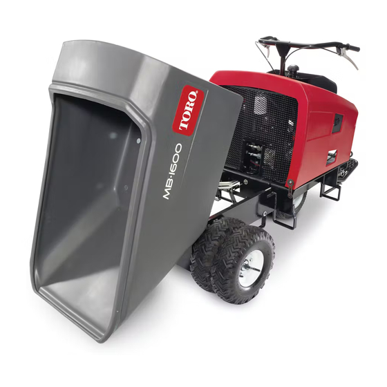
Mud buggy
Hide thumbs
Also See for MB-1600:
- Operator's manual (36 pages) ,
- Operator's manual (32 pages) ,
- Operator's manual (36 pages)

Related Manuals for Toro MB-1600


Summary of Contents for Toro MB-1600
- Page 1 Operator’s Manual MB-1600 Mud Buggy Model—Serial Range 68038—405500000 and Up *3451-702* A 3451-702A Original Instructions (EN)
-
Page 2: Table Of Contents
Because in some areas there are local, state, or federal regulations requiring that a spark arrester be used on the engine of this machine, a spark arrester is available as an option. If you require a spark arrester, contact your Authorized Service Dealer. Genuine Toro spark arresters are approved by the USDA Forestry Service. -
Page 3: Disclaimers And Regulatory Information
Engine Controls ..........................3–3 Specifications ............................ 3–5 Attachments/Accessories....................... 3–5 Chapter 4: Operation ........................... 4–1 Before Operation ..........................4–1 Before Operation Safety ......................4–1 Fuel ..............................4–2 Performing Daily Maintenance ....................4–3 During Operation ..........................4–3 During Operation Safety ......................4–3 Starting the Engine........................ - Page 4 Chapter 6: Storage..........................6–1 Storage Safety ..........................6–1 Preparing the Machine for Storage Over 30 Days..............6–1 Chapter 7: Troubleshooting ....................... 7–1 Chapter 8: California Proposition 65 Warning Information ............8–1 Disclaimers and Regulatory Information: Page 4 3451-702 A...
-
Page 5: Chapter 1: Introduction
Whenever you need service, genuine Toro parts, or additional information, contact an Authorized Service Dealer or Toro Customer Service and have the model and serial numbers of your product ready. These numbers are located on the serial plate on your product . -
Page 6: Manual Conventions
Manual Conventions This manual identifies potential hazards and has safety messages identified by the safety- alert symbol, which signals a hazard that may cause serious injury or death if you do not follow the recommended precautions. g000502 This manual uses 2 words to highlight information. Important calls attention to special mechanical information and Note emphasizes general information worthy of special attention. -
Page 7: Chapter 2: Safety
Chapter 2 Safety General Safety • Read and understand the contents of this Operator’s Manual before starting the engine. • Do not operate the machine without all guards and other safety protective devices in place and functioning properly on the machine. •... - Page 8 Decal Part: 125-4958 decal125-4958 Read the Operator’s Manual for information on Read the Operator's Manual for information on shutting off the engine—1) Set the throttle to slow; starting the engine—1) Engage the parking brake; 2) Engage the parking brake; 3) Set the drive to 2) Set the drive to neutral;...
- Page 9 Decal Part: 125-4961 Reverse 125-4961 decal125-4961 Decal Part: 125-4962 Engage the parking brake. Disengage the parking brake. decal125-4962 Decal Part: 125-4963 Warning—stay away from hot surfaces. decal125-4963 3451-702A Page 2–3 Safety: Safety and Instructional Decals...
- Page 10 Decal Part: 125-4964 Read the Operator’s Manual for hydraulic oil information. decal125-4964 Decal Part: 125-4967 Lift point decal125-4967 Decal Part: 125-6694 Tie-down location decal125-6694 Safety: Safety and Instructional Decals Page 2–4 3451-702 A...
- Page 11 Decal Part: 125-8190 Press down on the pedal to engage the service brake. Release the pedal to disengage the service brake. decal125-8190 Decal Part: 127-2855 decal127-2855 Tipping hazard—do not drive forward with the Warning—read the Operator’s Manual; wear hopper raised; drive slowly with the hopper hearing protection.
- Page 12 Decal Part: 130-2844 Release the pedal to lower the hopper. Press down on the pedal to raise the hopper. decal130-2844 Decal Part: 133-8062 decal133-8062 Safety: Safety and Instructional Decals Page 2–6 3451-702 A...
-
Page 13: Chapter 3: Product Overview
Chapter 3 Product Overview Operator platform Steer tires Reverse-speed-control lever Drive tires Hopper Handle bars Forward-speed-control lever Dump handle/pedal Fuel tank Parking brake Brake pedal G356654 Controls Brake Pedal Press down on the brake pedal to stop the machine. g356774 3451-702 A Page 3–1 Product Overview... -
Page 14: Parking Brake
Parking Brake Engage Disengage g357455 Drive Controls g356775 Dump Controls Dump switch Dump pedal Lower the hopper Dump the hopper g025722 Product Overview: Controls Page 3–2 3451-702 A... -
Page 15: Fuel Gauge
Fuel Gauge g357274 Engine Controls Recoil starter Fuel shut-off valve Choke lever Throttle lever Fuel tank shut off valve On/Off switch G356777 Choke Control the choke before starting a NGAGE cold engine. the choke when the ISENGAGE engine is warm. G356784 3451-702A Page 3–3... - Page 16 Engine Controls (continued) Engine On/Off Control G356822 Fuel Shutoff Controls Fuel tank shutoff control—use when performing maintenance and storing the machine. Engine fuel shutoff control—use before starting and after stopping the machine. g356785 Recoil Starter Use the recoil starter handle to start the engine. Throttle Control g357324 Product Overview: Controls...
-
Page 17: Specifications
Discharge height 16.5 cm (6.5 inches) Attachments/Accessories A selection of Toro approved attachments and accessories is available for use with the machine to enhance and expand its capabilities. Contact your Authorized Service Dealer or authorized Toro distributor or go to www.Toro.com... -
Page 18: Chapter 4: Operation
Chapter 4 Operation Before Operation Before Operation Safety General Safety • Never allow children or untrained people to operate the machine. Local regulations may restrict the age of the operator. The owner is responsible for training all operators and mechanics. •... -
Page 19: Fuel
Before Operation Safety (continued) • If you spill fuel, do not attempt to start the engine; avoid creating any source of ignition until the fuel vapors have dissipated. • Do not fill containers inside a vehicle or on a truck or trailer bed with a plastic liner. Always place containers on the ground, away from your vehicle before filling. -
Page 20: Performing Daily Maintenance
Fuel (continued) Filling the Fuel Tank 1. Park the machine on a level surface, shut off the engine, and allow it to cool. 2. Clean around the fuel tank cap and remove it. 3. Add fuel to the fuel tank until the level is just below the bottom of the filler neck. Note: This space in the tank allows fuel to expand. - Page 21 During Operation Safety (continued) • Operate the engine only in well-ventilated areas. Exhaust gasses contain carbon monoxide, which is lethal if inhaled. • Never leave a running machine unattended. • Operate the machine only in good visibility and appropriate weather conditions. Do not operate the machine when there is the risk of lightning.
-
Page 22: Starting The Engine
During Operation Safety (continued) • Avoid starting, stopping, or turning the machine on a slope. Avoid making sudden changes in speed or direction; turn slowly and gradually. • Keep all movements on slopes slow and gradual. Do not make sudden changes in speed or direction. -
Page 23: Shutting Off The Engine
Starting the Engine (continued) 9. Pull the recoil starter handle out until positive engagement results, then pull it vigorously to start the engine. IMPORTANT Do not pull the recoil rope to its limit or let go of the starter handle when the rope is pulled out;... -
Page 24: Operating The Machine
Operating the Machine 1. Step onto the machine. CAUTION When mounting the machine, slippery or uneven ground may cause you to fall. Always have 3 out of 4 arms/legs in contact with the machine when you mount or dismount the machine. g357348 2. - Page 25 Operator Platform (continued) WARNING The operator platform is heavy and may cause injury when you raise or lower it. Carefully lower or raise the operator platform, as suddenly dropping it could injure you. • Do not put your hands or fingers in the platform-pivot area when lowering or raising the operator platform.
-
Page 26: Operating The Hopper
Operator Platform (continued) Lowering the Platform 1. Push the platform against the cushion to release pressure on the latch pin. 2. Pull the latch pin out and lower the platform. G384422 Raising the Platform 1. Pull out the latch pin and raise the platform. 2. -
Page 27: After Operation
Operating the Hopper (continued) 2. Dump the hopper by either of the following: • Pull the dump handle down. • Press down on the forward part of the dump pedal 3. Move the hopper to the upright position either of the following: •... - Page 28 Haul the Machine (continued) WARNING Driving on the street or roadway without turn signals, lights, reflective markings, or a slow-moving-vehicle emblem is dangerous and can lead to accidents causing personal injury. Do not drive the machine on a public street or roadway. Selecting a Trailer WARNING Loading a machine onto a trailer or truck increases the possibility of tip-over and...
- Page 29 Haul the Machine (continued) Loading the Machine WARNING Loading a machine onto a trailer or truck increases the possibility of tip-over and could cause serious injury or death. • Use extreme caution when operating a machine on a ramp. • Load and unload the machine with the heavy end up the ramp. •...
- Page 30 Haul the Machine (continued) 7. Use the metal tie-down loops to securely fasten the machine to the trailer or truck with straps, chains, cable, or ropes . Refer to local regulations for tie-down requirements. IMPORTANT Do not use the tie-down loops to lift the machine. Unloading the Machine 1.
-
Page 31: Removing The Outer Wheels
Removing the Outer Wheels You can reduce the width of the machine from 117 cm (46 inch) to 91 cm (36 inch), using a wood block and a crow bar. IMPORTANT The maximum payload is reduced to 850 kg (1875 lb) when operating the machine without the dual wheels. -
Page 32: Chapter 5: Maintenance
• Use the cylinder lock to secure the hopper in the raised position. • Never tamper with safety devices. • To ensure safe, optimal performance of the machine, use only genuine Toro replacement parts. Replacement parts made by other manufacturers could be dangerous, and such use could void the product warranty. -
Page 33: Recommended Maintenance Schedule
• Safely relieve all pressure in the hydraulic system before performing any work on the hydraulic system. Recommended Maintenance Schedule Maintenance Qty Description Maintenance Procedure Part No. Service Interval After the first 50 Change the engine oil., page 5–8 hours Check the engine oil level., page 5–8 Check the brake pedal., page 5–... -
Page 34: Pre-Maintenance Procedures
Maintenance Qty Description Maintenance Procedure Part No. Service Interval 361-9 Paint Yearly or before Touch up chipped paint. storage 361-10 Paint Pre-Maintenance Procedures Moving a Non-Functional Machine In an emergency, you can move the machine forward by actuating the bypass valve the hydraulic pump and pushing or towing the machine. -
Page 35: Removing The Cowl
Lifting the Machine (continued) 1. Place the platform in the raised position. 2. Place the hopper in the dump position. 3. Attach a chain or straps to each of the 3 lift points located under the hopper. 4. Remove any slack in the chains or straps to ensure that the machine is properly balanced. -
Page 36: Lubrication
Removing the Cowl (continued) 4. When finished, install the cowl and secure the latches. g358757 Lubrication Greasing the Machine Grease Type: General-purpose grease. Note: Remove the blue protection caps, if applicable, before greasing and replace when finished. 1. Park the machine on a level surface and engage the parking brake. 2. -
Page 37: Engine Maintenance
Greasing the Machine (continued) 4. Connect a grease gun to each fitting. G357166 5. Pump grease into the fittings until grease begins to ooze out of the bearings (approximately 3 pumps). 6. Wipe up any excess grease. Engine Maintenance Servicing the Air Cleaner IMPORTANT Do not operate the engine without the air-cleaner element. -
Page 38: Engine Oil Service
Servicing the Air Cleaner (continued) 2. Remove the wing nut that secures the air- cleaner cover to the air cleaner and remove the cover . Clean the cover thoroughly. 3. Remove the wing nut from the air filter and remove the filter. 4. - Page 39 Engine Oil Service (continued) Checking the Engine-Oil Level 1. Park the machine on a level surface and shut off the engine. Allow the engine to cool. 2. Unlatch and remove the cowl. 3. Clean around the oil filler cap/dipstick G376152 4.
-
Page 40: Replacing The Spark Plug
Engine Oil Service (continued) 2. Park the machine on a level surface, engage the parking brake, and shut off the engine. 3. Have a funnel ready to place under the oil drain plug, then remove the plug and place the funnel under the plug to guide the oil into a container. CAUTION Components will be hot if the machine has been running. -
Page 41: Fuel System Maintenance
Cleaning the Blower Housing (continued) IMPORTANT Operating the engine with dirty or plugged cooling fins and/or cooling shrouds removed causes engine damage due to overheating. Fuel System Maintenance Cleaning the Sediment Cup 1. Move the fuel valve to the O position 2. -
Page 42: Draining The Fuel Tank
Replacing the Fuel Filter (continued) 6. Replace the filter Note: Ensure that the flow-direction arrow on the replacement filter points toward the engine. G376154 7. Connect the spark plug wire. 8. Open the tank shutoff valve and turn on the engine switch, and check for fuel leaks. Draining the Fuel Tank 1. -
Page 43: Inspecting The Tires
Checking the Transmission Neutral Position (continued) 1. Put the hopper in the dump position shut off the engine. 2. Remove the cowl 3. Remove the throttle lever cables at the transmission. 4. Lift the front wheels off the ground, and support the machine with a jack stand. -
Page 44: Brake Maintenance
Brake Maintenance Checking the Brake Pedal 1. Move the machine to a level, open area. 2. E the parking brake and start the engine. NGAGE 3. Set the engine throttle to the F position. 4. Step on the brake pedal 5. -
Page 45: Hydraulic System Maintenance
• Toro PX Extended Life Hydraulic Fluid (refer to your Authorized Service Dealer for more information) • If either of the above Toro fluids are not available, you may use another Universal Tractor Hydraulic Fluid (UTHF), but they must be only conventional, petroleum- based products. -
Page 46: Checking The Hydraulic Fluid
20 ml (2/3 fl oz) bottles. One bottle is sufficient for 15 to 22 L (4 to 6 US gallons) of hydraulic fluid. Order Part No. 44- 2500 from your Authorized Toro Dealer. Checking the Hydraulic Fluid... -
Page 47: Replacing The Hydraulic Filter
Changing the Hydraulic Fluid (continued) 3. Slowly loosen the hex nut on the bottom of the cap. CAUTION The hydraulic breather/filler cap is designed to pressurize the reservoir to 34 kPa (5 psi). Loosen the cap slowly to avoid injury whenever adding oil or working on the hydraulic system. -
Page 48: Checking The Hydraulic Lines
Replacing the Hydraulic Filter (continued) 3. Place a drain pan under the filter and replace it as shown: g359049 4. Clean up any spilled fluid. 5. Start the engine and let it run for 2 minutes to purge air from the system. 6. - Page 49 Removing Debris (continued) 4. Wipe away debris from the air cleaner. 5. Clean any debris buildup on the engine and in the transmission with a brush or blower. IMPORTANT It is preferable to blow dirt out rather than washing it out. If you use water, keep it away from electrical items and hydraulic valves.
-
Page 50: Chapter 6: Storage
Chapter 6 Storage Storage Safety • Shut off the engine, remove the key (if applicable), wait for all moving parts to stop, and allow the machine to cool before storing it. • Do not store the machine or fuel near flames. Preparing the Machine for Storage Over 30 Days 1. - Page 51 7. Prepare the fuel system. A. Add a petroleum-based fuel stabilizer/conditioner to the fuel in the tank. Do not use an alcohol-based stabilizer (ethanol or methanol). B. Run the engine to distribute conditioned fuel through the fuel system for 5 minutes. C.
-
Page 52: Chapter 7: Troubleshooting
Chapter 7 Troubleshooting The engine does not start. Possible Cause Corrective Action The On/Off switch is in the O position. Move the switch to the O position. The fuel-shutoff valve is closed. Open the fuel-shutoff valve. The engine oil is low. Before the oil level in Check the engine oil. - Page 53 The machine does not stop. Possible Cause Corrective Action The hydraulic or transmission system is Contact your Authorized Service Dealer. damaged. 3451-702A Page 7–2 Troubleshooting: Storage Safety...
-
Page 54: Chapter 8: California Proposition 65 Warning Information
Chapter 8 California Proposition 65 Warning Information What is this warning? You may see a product for sale that has a warning label like the following: WARNING: Cancer and Reproductive Harm—www.p65Warnings.ca. gov. What is Prop 65? Prop 65 applies to any company operating in California, selling products in California, or manufacturing products that may be sold in or brought into California. - Page 55 While the exposure from Toro products may be negligible or well within the “no significant risk” range, out of an abundance of caution, Toro has elected to provide the Prop 65 warnings. Moreover, if Toro does not provide these warnings, it could be sued by the State of California or by private parties seeking to enforce Prop 65 and subject to substantial penalties.
- Page 56 Notes:...
Need help?
Do you have a question about the MB-1600 and is the answer not in the manual?
Questions and answers