Table of Contents
Advertisement
Test report no. 22012524
Page 1 of 2
EUT: cVEND PIN
FCC ID: PJMCVPIN
FCC Title 47 CFR Part 15
Date of issue: 2022-06-14
Annex acc. to FCC Title 47 CFR Part 15
relating to
FEIG ELECTRONIC GmbH
cVEND PIN
Annex no. 5
User Manual
Functional Description
Title 47 - Telecommunication
Part 15 - Radio Frequency Devices
Subpart C – Intentional Radiators
ANSI C63.4-2014
ANSI C63.10-2013
Date: 2019-11-20
Created: Trepper
Reviewed: Ftouhi
Released: Hittig-Rademacher
Vers. No. 3.19
TÜV NORD Hochfrequenztechnik GmbH & Co. KG
Tel.: +49 221 8888950
LESKANPARK, Gebäude 10, Waltherstr. 49-51, 51069 Köln, Germany
Advertisement
Table of Contents

Summary of Contents for Feig Electronic cVEND PIN
- Page 1 Test report no. 22012524 Page 1 of 2 EUT: cVEND PIN FCC ID: PJMCVPIN FCC Title 47 CFR Part 15 Date of issue: 2022-06-14 Annex acc. to FCC Title 47 CFR Part 15 relating to FEIG ELECTRONIC GmbH cVEND PIN Annex no.
- Page 2 Test report no. 22012524 Page 2 of 2 EUT: cVEND PIN FCC ID: PJMCVPIN FCC Title 47 CFR Part 15 Date of issue: 2022-06-14 User Manual / Functional Description of the test equipment (EUT) Date: 2019-11-20 Created: Trepper Reviewed: Ftouhi Released: Hittig-Rademacher Vers.
- Page 3 PAYMENT INSTALLATION cVEND PIN Unattended PIN Entry Terminal with On-Board Contactless Reader M90113-10e-PY-B...
- Page 4 Composition of the information in this document has been done to the best of our knowledge. FEIG ELECTRONIC GmbH does not guarantee the correctness and completeness of the details given in this manual and may not be held liable for damages ensuing from incorrect or incomplete information. Since, despite all our efforts, errors may not be completely avoided, we are always grateful for your useful tips.
-
Page 5: Table Of Contents
PAYMENT Contents Contents Contents Warnings – Read Before Start-Up! Safety Instructions ......................5 Security Instructions ......................5 Characterization Functional Elements Front Side ........................... 7 Key Pad ..........................8 Back Side ........................... 9 Mechanical Integration Dimensions ........................12 Privacy Shield ........................15 Connectors Connector X1 –... - Page 6 PAYMENT Contents Setup Activation ......................30 User ID Setup ........................31 Removal Protection Activation ..................32 Maintenance and Cleaning Cleaning ........................... 33 Battery ..........................33 User Interface Boot Process ........................34 Update Installation Indicators ..................34 Security Tamper ......................34 Technical Data Payment Standard Compliance ..................
-
Page 7: Warnings - Read Before Start-Up
25 cm between the device or the antenna and your cardiac pacemaker. 1.2 Security Instructions ► The information given in the separate document cVEND PIN Security Policy must be observed! ► DO NOT DISASSEMBLE ANY PART! The device contains a battery-powered security circuit. The security circuit will be triggered if security relevant parts are disassembled. -
Page 8: Characterization
For acceptance of traditional smart cards with contacts cVEND PIN can be combined with the secure and robust hybrid smart card reader cVEND SHRC which is designed for ID1 size cards with magnetic stripe and smarts cards with contacts. -
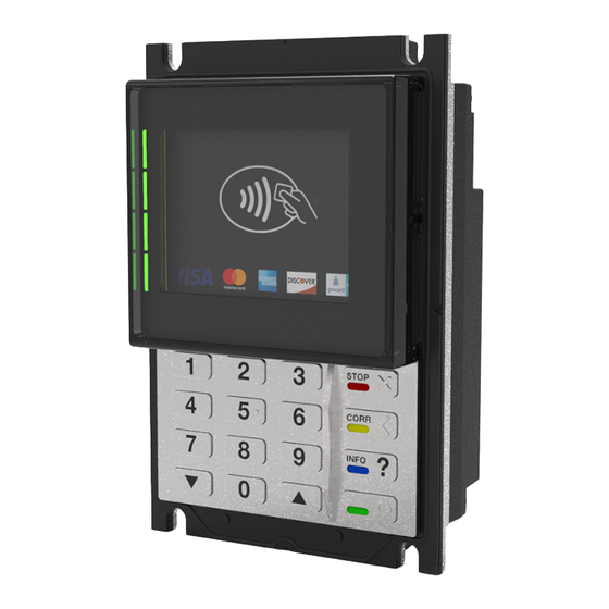
Page 9: Functional Elements
Functional Elements 3 Functional Elements Functional Elements 3.1 Front Side Fig. 2: cVEND PIN front view – not installed Page 7 of 38... -
Page 10: Key Pad
Table 1: Front side elements 3.2 Key Pad The stainless steel cVEND PIN key pad with clear tactile feedback and embossed symbols is designed for indoor and outdoor applications and provides barrier-free operation. The key pad function is under software control. The functionality of the function keys (2) and the navigation keys (4, 5) may vary depending on the installed application. -
Page 11: Back Side
Functional Elements 3.3 Back Side Fig. 4: cVEND PIN rear view – not installed Label Description Intended Use Power Supply and MDB Interface MDB interface: ECR interface for vending machines USB Device ECR interface COM Port 0 (RS232) ECR interface... -
Page 12: Mechanical Integration
Mechanical Integration For flush integration into a front panel the cVEND PIN has to be placed in a corresponding cutout and has to be pressed against the front plate by screwing on the four screwing points provided for this purpose. For fastening threaded bolts M4 x 12 mm are recommended. - Page 13 Mechanical Integration Fig. 6: cVEND PIN recommended front panel cut-out Page 11 of 38...
-
Page 14: Dimensions
Mechanical Integration 4.1 Dimensions Fig. 7: cVEND PIN dimensions – front view Manufacturing tolerance of cVEND PIN: 82 mm x 119,9 mm (+/- 0,30) Page 12 of 38... - Page 15 Mechanical Integration Fig. 8: cVEND PIN dimensions – rear view Page 13 of 38...
- Page 16 Mechanical Integration Fig. 9: cVEND PIN dimensions – side view Page 14 of 38...
-
Page 17: Privacy Shield
315° and 45°, the card holder obscures an observer's view of the PIN pad with his body (a symmetrical design must meet the minimum requirements at each point). The cVEND PIN Security Guidance includes more details on how the privacy shield has to be designed. The angles in the figures below are defined as follows: α... - Page 18 Mechanical Integration Page 16 of 38...
-
Page 19: Connectors
Connectors 5 Connectors Connectors The connector I/O PINs are described from the cVEND PIN view. A cVEND PIN input must be connected to one output or vice versa. 5.1 Connector X1 – Power Supply and MDB Interface Fig. 10: Connector X1 – Power/MDB... -
Page 20: Standby Mode / Wake-Up
The host controller can awake the cVEND by pulling down the wake-up line. Fig. 11: cVEND PIN Internal Wake-Up Circuit Wake-up “OK” Key: Pressing the “OK” key on the key pad will awake the cVEND. -
Page 21: Connector X2 - Usb Device Interface
5.3 Connector X2 – USB Device Interface At connector X2 a USB device interface is provided where a USB host can be connected. The cVEND PIN is designed as a self-powered device. Power supply via USB interface is not possible. -
Page 22: Connector X3 - Com 0 (Rs232 V.24 Interface)
Connectors 5.4 Connector X3 – COM 0 (RS232 V.24 Interface) X3 is the connector for an RS232 interface on V.24 level and is primarily intended as a cash register interface. Fig. 13: Connector X3 – COM 0 Label Direction Remarks Device RXD Device TXD Wake-Up... -
Page 23: Connector X4 - Usb Host 2 Interface
Connectors 5.5 Connector X4 – USB Host 2 Interface At connector X4 a USB host interface is provided where a USB device can be connected. The USB host function depends on the firmware / software version. Fig. 14 Connector X4 – USB 2 Host Required Connector: USB 2.0 type A: max. -
Page 24: Connector X5 - Ethernet Interface
Connectors 5.6 Connector X5 – Ethernet Interface Ethernet is provided on the RJ45 connector as 10/100 Base-T network with automatic polarity correction during auto-negotiation and 10 Base-T signal reception. CAT5 cables are recommended to ensure a reliable operation at 10 Mbps or 100 Mbps. Fig. -
Page 25: Connector X6 - Auxiliary
Connectors 5.7 Connector X6 - Auxiliary On connector X6 an electrically isolated opto-coupler digital output and a connector for an external buzzer are provided. The opto-coupler digital output is controlled by software and can be used to control a parking barrier for example. - Page 26 Connectors Fig. 17: X6 – AUX Schematic External Buzzer: The external buzzer can be powered by the 5 V DC voltage provided on X6.1. To increase the sound level and depending on the external buzzer it can also be powered by an external power supply. Observe the electrical parameters in Table 9: Pin Assignment Auxiliary Connector (X6).
-
Page 27: Connector X7 - Usb Host 1
Connectors 5.8 Connector X7 – USB Host 1 On connector X7 a USB host interface is provided, intended to be used for static connected interface devices. USB host function depends on firmware/software version. Fig. 20: Pin Assignment USB Host 1 on Connector X7 Label Direction 5 V DC (max. -
Page 28: Connector X8 - Cvend Shcr
Connectors 5.9 Connector X8 – cVEND SHCR Connector X8 is a COM port which is the connector for Secure Hybrid Card Reader cVEND SHCR. The related connection cable is included in the scope of delivery of cVEND SHCR. Fig. 21: Connector X8 – SHCR Connector Label Direction SHCR... -
Page 29: Connector X9 - Com 2 (Rs232 V.24)
Connectors 5.10 Connector X9 – COM 2 (RS232 V.24) At connector X9 a serial interface (UART#2) on RS232 V.24 level is provided which is used on development devices to access the Linux console. Fig. 22: Connector X9 – COM 2 Label Direction Device RxD... -
Page 30: Sam Sockets (S1, S2)
Connectors 5.11 SAM Sockets (S1, S2) The cVEND PIN is equipped with 2 SAM sockets which are located behind the hinged cover on the back side of the device. Fig. 23: SAM Socket Location and Handling Page 28 of 38... -
Page 31: Installation And Setup
6.1 Installation Before installing, visually inspect the device for any discrepancies to the official product data or unauthorized modifications. More details can be found in the cVEND PIN Security Policy. For installation follow these steps: 1. Make sure that the intended installation are is clean and even. -
Page 32: Setup Activation
Installation and Setup 6.2 Setup Activation To activate the cVEND PIN setup menu the Service Mode Switch S3 (under the hinged cover) must be pressed. After activation please follow the display instructions. Fig. 24: Position of Service Mode Switch T1... -
Page 33: User Id Setup
Factory new devices do not have any User ID stored except if User IDs are preconfigured on optional request. The cVEND PIN has an easy to use User ID administration function. Adding and removing of a User ID can be carried out either via secure host process or manually on the terminal. This chapter only describes the manual User ID setup process. -
Page 34: Removal Protection Activation
(after initial installation or reinstallation). This process can be carried out only if the cVEND PIN device is mounted into the enclosing housing and it is ensured the removal protection switches (S1, S2) are pressed. The same applies to the Secure Hybrid Card Reader cVEND SHCR. -
Page 35: Maintenance And Cleaning
7.2 Battery The cVEND PIN contains a lithium battery to supply the real time clock and security circuit. If the battery is discharged, removed or short-circuited, the terminal can no longer be operated and will change into tamper detected state (see 8.3). -
Page 36: User Interface
The device contains tamper mechanisms that will trigger when a physical penetration attempt of the device is detected. A tamper event is signalized by the cVEND PIN after power-on. Such a device has to be replaced. Repair is only possible in the secure manufacturer environment at FEIG ELECTRONIC GmbH. -
Page 37: Technical Data
Technical Data 9 Technical Data Technical Data • Housing Stainless steel with glass and polycarbonate • Total: 92,5 x 141 x 47 mm Dimension (W x H x D) • Visible: 82 x 120 x 14 mm • Weight 450 g •... -
Page 38: Payment Standard Compliance
Technical Data • 2,8” high-brilliance color display 320 x 240 pixel (500 cd/m²); impact, scratch and fire resistant front glass • User Interface 4 high brightness green LEDs for contactless transactions • internal multi-frequency buzzer and audio output • Stainless steel key pad; 16 keys with from top illumination Key Pad •... -
Page 39: Radio Approvals
9.2 Radio Approvals 9.2.1 Declaration of Conformity (CE) Hereby FEIG ELECTRONIC GmbH declares that the radio equipment type cVEND PIN is in compliance with Directive 2014/53/EU. The full text of the EU declaration of conformity is available at the following internet address: https://www.feig.de/en/service/eu-declarations-of-conformity/... - Page 40 Technical Data Installation with FCC / IC Approval: FCC-/IC-NOTICE: To comply with FCC Part 15 Rules in the United States / with IC Radio Standards in Canada, the system must be professionally installed to ensure compliance with the Part 15 certification / IC certification.
Need help?
Do you have a question about the cVEND PIN and is the answer not in the manual?
Questions and answers