Table of Contents
Advertisement
TWIN DISC
TWIN DISC
TWIN DISC
TWIN DISC
TWIN DISC
INCORPORA
INCORPORATED
INCORPORA
INCORPORA
INCORPORA
Oper
Oper a a a a a tor'
Oper
tor'
tor' s s s s s
tor'
Oper
Oper
tor'
Manual
Manual
Manual
Manual
Manual
TED
TED
TED
TED
P P P P P o o o o o w w w w w er Shift
T T T T T r r r r r ansmission
ansmission
ansmission
ansmission
ansmission
Components:
TA-90-8501 Transmission
8-FLW-2302-0 Torque Converter
TDEC-400 Electronic Control
Document Number: 1020510
er Shift
er Shift
er Shift
er Shift
Advertisement
Table of Contents

Related Manuals for Twin Disc TA-90-8501


Summary of Contents for Twin Disc TA-90-8501
- Page 1 P P P P P o o o o o w w w w w er Shift er Shift er Shift er Shift er Shift T T T T T r r r r r ansmission ansmission ansmission ansmission ansmission Components: TA-90-8501 Transmission 8-FLW-2302-0 Torque Converter TDEC-400 Electronic Control Document Number: 1020510...
- Page 2 NOTICE Twin Disc, Incorporated makes no warranty or guaranty of any kind, expressed, implied or otherwise, with regard to the information contained within this manual. Twin Disc, Incorporated has developed this manual through research and testing of the information contained therein. Twin Disc,...
- Page 3 Document Number 1020510 Revison 1 May, 2002 Power Shift Transmission System Operator’s Manual...
- Page 5 (24) months from the date of original shipment by Twin Disc, Incorporated to the original customer, but not to exceed twelve (12) months of service, whichever occurs first. This is the...
- Page 6 TWIN DISC, INCORPORATED Flat Rate Hours Allowance (Hourly Labor Rate Must Be Acceptable to Twin Disc, Incorporated) * Travel and related expenses are not included as a part of Twin Disc General Unit Warranty. GENERAL UNITS Model Series R&R Repair & Test...
-
Page 7: Table Of Contents
Table of Contents Twin Disc, Incorporated Table of Contents Introduction ............9 General Information ................9 Replacement Parts ................10 Preventative Maintenance/Troubleshooting ......... 11 Safety ....................12 Sources of Service Information ............13 Warranty ....................14 Description and Specifications ......15 General....................15 Description .................. - Page 8 Table of Contents Twin Disc, Incorporated Preventative Maintenance ........51 General ....................51 Hydraulic System ................52 Periodic Visual Inspection ............... 56 Hydraulic System Pressure Checks ..........59 Troubleshooting ..........61 General ....................61 Pressure and Flow Test Kit .............. 62 Troubleshooting Discussion ............63 Problems that Show No Fault Messages in the Display ....
-
Page 9: Introduction
General Information This publication provides the information necessary for the operation and maintenance of the Twin Disc, Incorporated equipment specified on the cover of this manual. Specific engineering details and performance characteristics can be obtained from the Product Service Department of Twin Disc, Incorporated, Racine, Wisconsin, USA. -
Page 10: Replacement Parts
Parts Lists Engineering assembly drawings are provided in appropriate sections of this manual to facilitate ordering spare or replacement parts. Current bill of materials are available from Twin Disc or the nearest Authorized Twin Disc Distributor. Ordering Parts All replacement parts or products (including hoses and fittings) must be of Twin Disc origin or equal, and otherwise identical with components of the original equipment. -
Page 11: Preventative Maintenance/Troubleshooting
Lifting Bolt Holes Most Twin Disc products have provisions for attaching lifting bolts. The holes provided are always of adequate size and number to safely lift the Twin Disc product. -
Page 12: Safety
Safety General Safe practices must be employed by all personnel operating and servicing this unit. Twin Disc, Incorporated will not be responsible for personal injury resulting from careless use of hand tools, lifting equipment, power tools, or unaccepted maintenance/operating practices. -
Page 13: Sources Of Service Information
Twin Disc, Incorporated Introduction Sources of Service Information Each series of manuals issued by Twin Disc, Incorporated is current at the time of printing. When required, changes are made to reflect advancing technology and improvements in state-of-the-art. Individual product service bulletins are issued to provide the field with immediate notice of new service information. -
Page 14: Warranty
Introduction Twin Disc, Incorporated Warranty Equipment for which this manual was written has a limited warranty. For details of the warranty, refer to the warranty statement at the front of this manual. Power Shift Transmission System Operator’s Manual #1020510... -
Page 15: Description And Specifications
General (Reference - Twin Disc Application # AN4019) The Twin Disc TA-90-8501 transmission is a hydraulically actuated power shift transmission, providing nine speeds forward. Used with this transmission is a Twin Disc torque converter model 8-FLW-2302-0. The transmission and torque converter are electronically controlled by a Twin Disc model TDEC-400 control. -
Page 16: Description
Description and Specifications Twin Disc, Incorporated Description There are two main sections of the transmission, a countershaft input section, and a planetary output section. The input section consists of three geared- together clutch shafts and a driven front output shaft. A 9-inch ball dump clutch is directly connected to, and driven by the input shaft, and when engaged, is directly connected to the front output shaft. -
Page 17: Regulator Valve Assembly
Description and Specifications Twin Disc, Incorporated Regulator Valve Assembly Pressure regulating valves for controlling main pressure, converter circuit pressure, and lube oil pressures are contained in the regulator valve assembly on the torque converter. The regulator valve on the torque converter also includes a cold oil relief for protection of the converter. -
Page 18: Special Features
Description and Specifications Twin Disc, Incorporated Special Features Clutches Hardened steel plates and organic fiber friction plates are used on all clutches. The 9-inch (input section) clutch is a ball-dump type clutch. The two 10.5-inch clutches (input section) are of the S dump valve configuration. The high range (output section) 12.5-inch clutch is of the LD dump valve configuration. -
Page 19: Specifications
Description and Specifications Twin Disc, Incorporated Specifications Normal Temperature Range: 180°-220° F (82°-104° C) Low Speed Pressures: Run at 715 rpm Main Pressure (X): 185 psi (1276 kPa) minimum at regulator. Clutch Apply Pressure (CL): 180 psi (1241 kPa) minimum at end caps and within 5 psi (34 kPa) of each other. - Page 20 Description and Specifications Twin Disc, Incorporated Engine speeds (approximate) (B J Services oil well fracturing rig with MTU/DDC 16V4000 engine, 3000 hp @ 1950 rpm) Full load 1950 rpm No load 1960 rpm Converter stall speed 1953 rpm TDEC-400 CONTROL Furnished with the transmission is the TDEC-400 electronic control.
-
Page 21: Operation
Operation Twin Disc, Incorporated Operation This section covers operation of the transmission, torque converter, and the associated hydraulic and electronic control system and their relationship to the engine and fracturing rig. The following paragraph (prior to start-up) provides information the fracturing rig operator needs to know to inspect the transmission and start the engine. -
Page 22: Checking Oil Level
Operation Twin Disc, Incorporated Checking Oil Level The oil level in the transmission must be checked before each use. Procedure for checking oil is as follows: Visually inspect the transmission, converter and drive line for security of mounting. Inspect plumbing and electrical components for security of attachment and/or leaks. -
Page 23: Basic System Description
Operation Twin Disc, Incorporated Basic System Description This section describes the function and relationship of the following major components in your power transmission system. Remote mounted transmission (TD90-8501) Engine mounted torque converter (8FLW-2302-0) Electronic control system (TDEC-400) Power Shift Transmission System Operator’s Manual #1020510... - Page 24 24VDC LIQUID CRYSTAL DISPLAY (VIA J1939) J1939 BUS OUTPUTS TRAN INPUT SPEED TRAN OUTPUT SPEED MISCELLANEOUS SYSTEM OIL TEMP POWER SOURCE TRANS FILTER DIFF PRESS SWITCH STATUS SWITCH INPUTS OIL LEVEL SWITCH STATUS CURRENT GEAR NEUTRAL DISCONNECT TRANSMISSION CONFIGURATION OIL LEVEL KEY SWITCH J1939 BUS INPUTS...
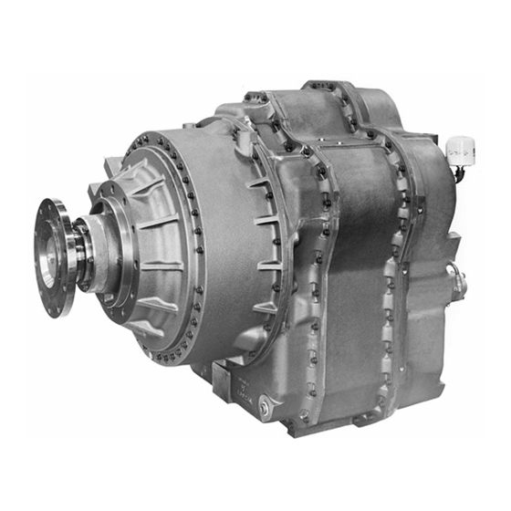
- Page 27 Operation Twin Disc, Incorporated Figure 4. Power Shift Transmission Side and Top View Power Shift Transmission System Operator’s Manual #1020510...
- Page 28 Operation Twin Disc, Incorporated Figure 5. Power Shift Transmission - Opposite Input - Side A Power Shift Transmission System Operator’s Manual #1020510...
-
Page 29: Transmission Component Summary
Operation Twin Disc, Incorporated Transmission Component Summary Torque Converter The torque converter is direct mounted to the engine flywheel housing, and its input member rotates with the flywheel. The transmission system oil pumps are geared to the input member, providing oil flow for transmission system operation. -
Page 30: Transmission Hydraulic System
Operation Twin Disc, Incorporated Transmission Hydraulic System See the hydraulic system schematic and piping diagram in the drawing section of this manual. The hydraulic system provides oil at correct pressures and flows for operation and lubrication of the transmission and torque converter. A cascading-type system is used, wherein the demand for pressure and flow for transmission functions are supplied in sequence from a single source (two pumps in tandem). - Page 31 Operation Twin Disc, Incorporated Main Pressure Regulator Valve The 52 gpm (197 L/min) pump flow is supplied to the main pressure regulator valve. This valve (located in the torque converter regulator valve assembly) maintains main system pressures for the application of the transmission clutches.
- Page 32 Operation Twin Disc, Incorporated Transmission Range Clutch Valves Four proportional cartridge valves are housed in three valve bodies that are located on the side of the input section of the transmission. Two proportional cartridge valves are housed in a valve body that is located on the planetary (rear) section of the transmission.
-
Page 33: Power Flow Through Transmission System
Operation Twin Disc, Incorporated Power Flow Through Transmission System The torque converter driving ring bolts directly onto the engine flywheel. The internal teeth of the driving ring mesh with the gear teeth on the rotating housing. The rotating housing provides input power to the impeller wheel of the torque converter. - Page 34 Operation Twin Disc, Incorporated Freewheel Function When the lockup clutch is engaged, the freewheel assembly allows the stator to freewheel. This improves the unit efficiency. The freewheel assembly locks the stator to the stator carrier during converter operation. This allows the torque converter to multiply engine torque.
-
Page 35: D.c. Power Supply
Operation Twin Disc, Incorporated D.C. Power Supply Input power to the electronic control is supplied by the customer. Refer to drawing #1019142 in Engineering Drawings. The positive lead should be connected directly to the positive terminal of the 24 volts DC battery post with no other loads. -
Page 36: Electronic Control System Overview
Operation Twin Disc, Incorporated Electronic Control System Overview The electronic control system monitors and coordinates functions of the torque converter and transmission system. Various external components are used to provide inputs for the control as well as outputs for operation of the transmission/ converter system. - Page 37 Operation Twin Disc, Incorporated Display Unit The display unit provides information to the operator about what range the transmission is in, and is also used while troubleshooting system problems. It also displays messages that may be generated by the electronic control sensing abnormal conditions in the transmission system.
- Page 38 Operation Twin Disc, Incorporated The Discreet Inputs Are: Transmission input speed sensor Transmission output speed sensor Transmission system oil temperature sensor Transmission filter differential pressure switch Transmission oil level switch Relay (customer supplied) to remove power from disconnectable clutch valve coils when in neutral...
- Page 39 Operation Twin Disc, Incorporated Based on all discreet input signals and J1939 Data Bus input signals, the electronic control sends signals out to various devices that cause the fracturing rig operation. The outputs are sent discreetly and also via the J1939 Data Bus.
-
Page 40: Tdec-400 Electronic Control System Components
Operation Twin Disc, Incorporated TDEC-400 Electronic Control System Components Electronic Control Monitors and controls the system through two wiring harnesses that attach to the control through three connectors. The control has no preferred mounting orientation. Transmission Range Selector The transmission range selector is customer supplied. Contact closures communicate with the electronic control the operators demand for upshifts or downshifts from the current range. - Page 41 Operation Twin Disc, Incorporated Second range is engaged. This range is achieved by upshifting from D-1 or downshifting from D-3. The transmission input shaft will turn at 3.57 times the transmission output shaft. Torque converter lockup clutch is automatically applied based on turbine speed.
- Page 42 Operation Twin Disc, Incorporated Eighth range is engaged. This range is achieved by upshifting from D-7. This is the maximum range allowed in this application, even though one additional range is available in the transmission. The transmission input shaft will turn at 1.00 times the transmission output shaft.
- Page 43 Operation Twin Disc, Incorporated Speed Sensors A voltage signal is generated as each tooth of a gear moves past the sensor. This results in an ac voltage signal with a frequency determined by the frequency of a tooth passing the sensor. The control is programmed with the number of teeth on the gear under the sensor and converts the frequency of pulses to determine gear/shaft RPM.
- Page 44 Operation Twin Disc, Incorporated Clutch Valve Coils Identical cartridge valves are used throughout the transmission system. The cartridge valves are identified as transmission range clutch valve coils, #1 through #6, and converter lockup clutch valve coil. They are used for controlling high pressure oil being directed to engage clutches.
-
Page 45: System Operation
Operation Twin Disc, Incorporated System Operation Start Up Select N on the range selector. This de-energizes the neutral disconnect relay which opens the contacts disconnecting all power from the transmission solenoids. Activate the start switch to supply electrical power to the starter circuit. -
Page 46: Fracturing Rig Operating Modes
Operation Twin Disc, Incorporated Fracturing Rig Operating Modes The control system is capable of three modes of operation: Drive mode , Work mode, and Diagnostic mode. The application is not using the Work mode (also known as hydraulic test mode) at the present time. The control could be commanded to the Work mode by an appropriate signal from the J1939 Data Bus, so will be discussed here. - Page 47 Operation Twin Disc, Incorporated Examples of Operation Basic: The oil well fracturing rig has been positioned and plumbed for pumping into an oil well. The operator starts the engine . A downshift is selected to lock the transmission shafts to allow for heating of the transmission system oil prior to begin pumping mud into the oil well.
- Page 48 Operation Twin Disc, Incorporated Normal Operation in Work Mode (also known as hydraulic test mode) Note: That this function may not be allowed in this application, however the transmission system is capable, and only requires the appropriate signals over the J1939 data bus to activate.
- Page 49 Operation Twin Disc, Incorporated Diagnostics Test Mode Diagnostics mode is available for controller system tests, and for ease in certain troubleshooting procedures. These tests verify operation of the controller, integrity and function of the external circuits, and provide a means to energize clutches individually.
-
Page 50: Operational Problems
Operation Twin Disc, Incorporated Operational Problems If the normal operation of the fracturing rig is not occurring. Please refer to Troubleshooting for the correct troubleshooting procedures. A clear understanding of the normal operation of the fracturing rig systems is essential to understand and troubleshoot any problems. - Page 51 Preventative Maintenance General Lubrication Lubrication for the TA-90-8501 transmission and the 8-FLW-2302-0 torque converter is accomplished by a full pressure system utilizing oil in the transmission sump. The transmission sump is the reservoir for all oil used in the hydraulic and lubrication systems. No lubrication is required beyond a daily check of the transmission oil level with the sight gauges.
- Page 52 Twin Disc, Incorporated Preventative Maintenance Hydraulic System Checking Oil Level The oil level in the transmission must be checked before each use. Procedure for checking oil is as follows: Visually inspect the transmission, converter and drive line for security of mounting.
- Page 53 Twin Disc, Incorporated Preventative Maintenance Oil level check: It is best to check the oil level after the oil well fracturing rig has been parked with the engine not running for at least 8 hours (or overnight). The fracturing rig should be parked on a level surface.
- Page 54 Twin Disc, Incorporated Preventative Maintenance Adding Oil The oil fill plug is located on the front face of the transmission on the left side as viewed from the rear. Refer to Figure 5 in Operation. Add or remove oil as needed to set proper level.
- Page 55 Provision is made for the filter and it is shown on the hydraulic schematic. The Twin Disc part number for replacement filter elements is 1016502. The Twin Disc filter or equivalent must be used to assure transmission warranty consideration.
- Page 56 When mating connectors, make sure they will mate properly. Coat pins and sockets only with dielectric compound to seal out moisture and corrosive substances (Twin Disc part number MA890 or Dow 4 Compound.) Locate and use the connector orientation key.
- Page 57 Twin Disc, Incorporated Preventative Maintenance Circular connectors must be hand tightened. Cable or harness bend radius must not be less than twenty times the cable diameter. Avoid twisting or winding cable along its axis during installation or removal. Whenever mating connectors, always inspect each for damage or defects.
- Page 58 Twin Disc, Incorporated Preventative Maintenance Hydraulic Lines, Flexible Hoses and Connectors Inspect all hydraulic lines, hoses, etc. for damage, sponginess, loose connections, chafing, etc. Correct leaks and replace damaged parts. Lines, hoses, etc. which show evidence of chafing should be replaced, rerouted, and/ or otherwise protected to prevent further damage.
- Page 59 Twin Disc, Incorporated Preventative Maintenance Hydraulic System Pressure Checks At the time of each transmission oil change the main and lube pressure of the transmission should be checked. See Figures 3, 4, 5, and 6 in Operation for pressure test point locations.
- Page 60 Twin Disc, Incorporated Preventative Maintenance Power Shift Transmission System Operator’s Manual #1020510...
- Page 61 Troubleshooting Twin Disc, Incorporated Troubleshooting General This section of the maintenance manual has been prepared to assist maintenance personnel in troubleshooting the power shift transmission and control. When troubleshooting the equipment, always remember to consider the entire power package of the oil well fracturing rig. Interaction between the transmission, the engine, and the oil well fracturing rig functions are all part of the troubleshooting process.
- Page 62 A portable pressure and flow test kit NU 2451 is available and contains the necessary equipment to accurately test and troubleshoot the hydraulic system of this Twin Disc unit. The kit contains pressure gauges, hoses, adapters, and flow meters. Contact the Twin Disc Service Department, Racine Wisconsin for specific information concerning this test kit.
- Page 63 Troubleshooting Twin Disc, Incorporated Troubleshooting Discussion The troubleshooting discussion includes the following topics: Problems that do not produce a fault message in the display Problems that do produce a fault message in the display Pressure testing for troubleshooting Recommended testing following field service repairs This should be performed after the installation of any major components such as transmission or torque converter.
- Page 64 Troubleshooting Twin Disc, Incorporated Problems that Show No Fault Messages in the Display See the troubleshooting flow charts, Figures 6 through 13, in Troubleshooting. Display is blank with the ignition in the on position Possible causes: No dc Power to the Display Verify that the proper dc voltage (24 volts) is supplied to the transmission display connector.
- Page 65 Troubleshooting Twin Disc, Incorporated Output driveshaft does not rotate when a forward range is selected. Note: If the display is blank, follow the procedures in Step 1. Note: If the display shows N when N is selected and shows either R when a downshift from neutral is selected, or D1 when an upshift from neutral is selected, then the display and control unit are functioning properly.
- Page 66 Troubleshooting Twin Disc, Incorporated Failed Clutch Solenoid If there is partial or full pressure on a clutch that is not selected, then remove and inspect the selector valve assembly. Replace the selector valve if necessary. Failed Clutch Pack DO NOT GET NEAR THE DRIVESHAFTS FOR THIS TEST!
- Page 67 Troubleshooting Twin Disc, Incorporated Locked Up Oil Fracturing Pump If no problems are detected during the clutch pressure tests, and the transmission input driveline comes to a stop when N is deselected, remove the output drive shaft from the transmission to verify that the transmission is not the cause of the problem.
- Page 68 Troubleshooting Twin Disc, Incorporated Output Driveshaft rotates in Warm-Up Mode (R) Possible causes: Failed Transmission Range Clutch Valve # 2, 4, or 5. If the display indicates R but the oil well fracturing rig input driveline and/ or the output driveline rotates, run Test 8 and check pressure to the applied clutch packs.
- Page 69 Troubleshooting Twin Disc, Incorporated Oil well fracturing rig output driveshaft only moves in some ranges Possible causes: Failed Transmission Range Clutch Valve If the display indicates a D range, and the input driveline rotates, but the oil well fracturing rig output driveline does not rotate, run Test 8 and check pressure to the range clutch packs.
- Page 70 Troubleshooting Twin Disc, Incorporated Oil well fracturing rig will not properly drive the pump in the upper transmission ranges when the pumping load should allow operation in these ranges. Possible Causes: Too much oil in transmission Adjust transmission oil level.
- Page 71 Troubleshooting Twin Disc, Incorporated Poor Engine Flywheel Scavenge Another possibility is that the engine flywheel housing is running with too much residual oil. The lube oil and normal leakage from the torque converter must be removed (scavenged) from the flywheel housing and returned to the transmission sump.
- Page 72 Troubleshooting Twin Disc, Incorporated Converter/transmission does not go into converter lockup Repeat the engine performance and flywheel housing scavenge checks as in step 5. Other possible causes: Lockup Clutch Disable Switch activated Be sure that the switch to disable the torque converter lockup clutch is in the proper position.
- Page 73 Troubleshooting Twin Disc, Incorporated Transmission and/or torque converter oil runs hot Possible causes: Too Much Oil in Transmission Adjust the transmission oil to the proper fill level. Poor Scavenge from Engine Flywheel Follow engine flywheel scavenge checks as outlined in step 5.
- Page 74 Troubleshooting Twin Disc, Incorporated Transmission system loses oil Possible causes: Leaks in Hoses and Fittings Check all hoses and fittings for leaks. Repair as needed. Seal Leak Between Engine and Torque Converter Check the engine oil. If the transmission continues to lose oil and the engine gains oil, it is likely that the engine crankshaft oil seal at the rear of the engine is leaking.
- Page 75 Troubleshooting Twin Disc, Incorporated Engine Cranking Problems Engine Won’t Crank (N Selected) Engine Cranks with Selector In Gear The oil well fracturing rig engine cranking system and power supply is discussed here, as the transmission control system criteria calls for the engine cranking to only occur when the transmission is in neutral.
- Page 76 Troubleshooting Twin Disc, Incorporated Vibrations in oil well fracturing rig Possible causes: Unbalanced or Bent Drive Shaft Inspect the input drive shaft between the torque converter and the transmission, and between the transmission output flange and the oil well fracturing rig pump. Look for bad universal joint assemblies. Verify that the universal joints are phased properly (universal joint yokes at each end of the center section must be parallel with each other).
- Page 77 Troubleshooting Twin Disc, Incorporated IGNITION SWITCH ON, DISPLAY IS BLANK Possible causes: No D.C. power to display, loose cables, failed display IS FUSE OR CIRCUIT REPLACE FUSE OR BREAKER CLOSED? RESET BREAKER 24 VOLTS PIN 1 TO 2 ON 6...
- Page 78 Troubleshooting Twin Disc, Incorporated ENGINE RUNNING, DRIVESHAFT WILL NOT ROTATE IN FWD DISPLAY SHOWS D Possible causes: low oil level, failed main pump, pump suction leak, failed clutch solenoid, failed clutch pack, locked axle or brakes IS PUMP LOCKED UP?
- Page 79 Troubleshooting Twin Disc, Incorporated OUTPUT SHAFT ROTATES IN WARM-UP (R) Possible Causes: Failed range clutch, failed range clutch valve DOES DISPLAY INDICATE R? DIAGNOSE SELECTOR R selected ENGINE AT IDLE, DOES THIS IS NORMAL IN WARM- TRANSMISSION DRIVESHAFT STOP IN REVERSE?
- Page 80 Troubleshooting Twin Disc, Incorporated OUTPUT DRIVESHAFT ROTATES ONLY IN SOME RANGES DOES DISPLAY INDICATE A DRIVE DIAGNOSE SELECTOR RANGE ENGINE AT IDLE, DOES RUN PRESSURE TEST 8 TRANSMISSION INPUT DRIVESHAFT EXTRA CLUTCH MAY BE STOP IN A DRIVE RANGE APPLIED...
- Page 81 Troubleshooting Twin Disc, Incorporated FRAC RIG WILL NOT OPERATE PUMP PROPERLY IN UPPER RANGES, CONVERTER DOES NOT GO INTO LOCK-UP POOR VEHICLE PERFORMANCE, LACKS POWER Possible causes: Low engine power, poor engine flywheel scavenge, Improper oil level, Converter Lock-up clutch or lockup clutch...
- Page 82 Troubleshooting Twin Disc, Incorporated HARSH SHIFTING INTO SOME RANGES Possible causes: Worn clutch pack, slow range clutch valve, improper pressure, improper speed signal, defective temperature sensor RUN TEST 5, TEST 6, and TEST 7 CHECK FOR DARK OR AND VERIFY INTEGRITY AND...
- Page 83 Troubleshooting Twin Disc, Incorporated TRANSMISSION / TORQUE CONVERTER RUNS HOT Possible causes: Too much oil in transmission, poor scavenge from engine flywheel, low oil flow thru converter and cooler, cooler not working properly PERFORM TORQUE ADJUST TRANSMISSION CONVERTER SCAVENGE OIL TO PROPER LEVEL...
- Page 84 Troubleshooting Twin Disc, Incorporated TORQUE CONVERTER SCAVENGE PUMP TEST Possible causes: Excessive Torque Converter leakage, obstructed pump inlet, suction leak IDLE ENGINE AT 700 RPM ENGINE OFF, DISCONNECT SCAVENGE AND MEASURE OIL FLOW PUMP HOSE FROM TRANSMISSION. RATE BY MEASURMENT AND DIRECT TOWARD BUCKET TIME.
- Page 85 Troubleshooting Twin Disc, Incorporated Problems that Show Fault Messages in the Display The purpose of this section is to help troubleshoot the TDEC-400 control system. This section is divided into component groups and/or specific fault messages. See the following pages for specific display fault information.
- Page 86 Troubleshooting Twin Disc, Incorporated Table 1. Fault Codes Display Message NVM Log Code Status Code TEST CONTROL ERROR I1 thru I24 Internal Control problem PWR PROB HIGH Power Test: VFILT Voltage PWR PROB Power Test: VFILT Voltage SELECT NEUTRAL Looking For Neutral Test...
- Page 87 Troubleshooting Twin Disc, Incorporated Display Faults Note: The following Fault Messages, Log Codes, and Status Codes are arranged and listed in alphabetical order. The TDEC-400 Display unit is a sealed non field serviceable device with two cable connectors and a backlit dot matrix LCD screen.
- Page 88 Troubleshooting Twin Disc, Incorporated PWR PROB Fault Message Log Code: I15, Status Code: High This fault message indicates that the supply voltage is too high as a result of a oil well fracturing rig power supply problem. If this condition exists for more than 5 seconds, the control will display the message, and after 2 minutes, will shut down.
- Page 89 Troubleshooting Twin Disc, Incorporated SELECT NEUTRAL Fault Message This fault message will be displayed at any time that the Neutral position of the selector must be verified for continued operation of the oil well fracturing rig. The message will be cleared when the switches indicate that Neutral has been selected.
- Page 90 Troubleshooting Twin Disc, Incorporated TRAN SYS FAULT Message -- INPUT SPD FREQ Log Code This fault message will be displayed if the control recognizes a speed signal from the transmission input speed sensor that is zero when there is an output speed signal.
- Page 91 Troubleshooting Twin Disc, Incorporated TRAN SYS FAULT Message -- LOCKUP Log Code -- CIRCUIT Status Code This fault message will be displayed if the control detects a short or open circuit to the torque converter range clutch valve. The valve will be turned off, and the message displayed.
- Page 92 Troubleshooting Twin Disc, Incorporated TRAN SYS FAULT Message -- OUT1 SPD Log Code This fault message will be displayed if the control recognizes an open or short in the transmission output speed sensor circuit. The display message will not be cleared until the fault is corrected and the controller is repowered by cycling the key switch.
- Page 93 Troubleshooting Twin Disc, Incorporated TRAN SYS FAULT Message -- OUT1 SPD FREQ This fault message will be displayed if the control recognizes a speed signal from the transmission output speed sensor that is zero when the transmission is in gear, and there is an input speed signal. Shifts from neutral to forward will be inhibited based on the transmission input speed.
- Page 94 Troubleshooting Twin Disc, Incorporated TRAN SYS FAULT Message -- SELECTOR FAULT Log Code This fault message will be displayed if the control detects an invalid signal in the selector circuit via the J1939 data bus. The transmission will be placed in computer neutral until the fault is corrected.
- Page 95 Troubleshooting Twin Disc, Incorporated TRAN SYS FAULT Message -- TranSol# (1 through 6) Log Code CIRCUIT Status Code This fault message will be displayed if the control detects an open circuit to the appropriate transmission range clutch valve. Computer neutral will be selected, and the message displayed until the fault is corrected and the control power cycled by the key switch.
- Page 96 Troubleshooting Twin Disc, Incorporated Unplug the pigtail of the indicated valve and measure the resistance of the solenoid valve itself. Expected resistance values are listed in Table 2. Place ohmmeter leads on the two sockets corresponding to the solenoid in question.
- Page 97 Troubleshooting Twin Disc, Incorporated TRAN SYS OVR HEAT Message -- SYST TMP Log Code CIRCUIT Status Code This fault message will be displayed if the transmission temperature signal is well outside of the range that would indicate a possible oil temperature condition.
- Page 98 Troubleshooting Twin Disc, Incorporated CONTROL SYSTEM FAULT MESSAGES 1 DISPLAY STATUS LOG CODE CAUSE ACTION MESSAGE CODE INTERNAL CONTROL REPLACE I1 - I24 CONTROL ERROR CONTROL PROBLEM CHECK VOLTAGE TOO CHARGING PWR PROB HIGH HIGH SYSTEM RUN TEST 2 CHECK...
- Page 99 Troubleshooting Twin Disc, Incorporated CONTROL SYSTEM FAULT MESSAGES 2 DISPLAY STATUS LOG CODE CAUSE ACTION MESSAGE CODE RESISTANCE OPEN TRANSMISSION TRAN SYS 1000 TO 1300 INPT SPD INPUT SPEED FAULT OHMS SENSOR SHORT RUN TEST 5 TRANSMISSION ADJUST OR TRAN SYS...
- Page 100 Troubleshooting Twin Disc, Incorporated CONTROL SYSTEM FAULT MESSAGES 3 DISPLAY STATUS LOG CODE CAUSE ACTION MESSAGE CODE SYSTEM REPAIR OR CIRCUIT TEMPERATURE REPLACE CIRCUIT BAD RUN TEST 5 INVESTIGATE SYSTEM TRAN SYS HOT OIL OR SYST TMP HIGH TEMPERATURE OVR HEAT...
- Page 101 Troubleshooting Twin Disc, Incorporated Diagnostic Test General See Figure 14 in Troubleshooting. A test routine is included within the control to aid in troubleshooting the external components of the control system. It is also helpful in troubleshooting the transmission and torque converter.
- Page 102 Troubleshooting Twin Disc, Incorporated Table 3. Engine Status for Diagnostic Testing Running Running Stopped Stopped Test Test Engine Engine Engine Engine Required Required Required Required Test 1: Test 1: Display Test Display Test Test 2: Test 2: Power Supply Test...
- Page 103 Troubleshooting Twin Disc, Incorporated Test 1. Display Test Upon entering the Troubleshooting Mode, the display test will be entered automatically. DISPLAY TEST will appear. After two seconds, all display segments/pixels will be displayed. After five seconds, the display will begin alternating between DISPLAY TEST (for one second), all segments/pixels (for one second), and the firmware checksum, CHECKSUM XXXX.
- Page 104 Troubleshooting Twin Disc, Incorporated Test 3. Range/Direction Selector Test During this test, the display will communicate with the push-button range selector via the J1939 data bus, and indicate the selection as seen by the control. If improper data is detected in any position, INVALID POSITION will be displayed (including between positions).
- Page 105 Troubleshooting Twin Disc, Incorporated Test 5. GP4 Controller Boundary Scan Test Two options will be displayed on the sub-menu: RUN TEST and EXIT TEST. Note that the engine should not be running to enter this test. Upon selecting RUN TEST, the control will automatically check all speed sensor and coil circuits for continuity and miscellaneous sensors to verify that the signal is in the proper range.
- Page 106 Troubleshooting Twin Disc, Incorporated If a fault is detected in a valve coil circuit during the testing, the top half of the display will indicate which coil is being tested, (LOCKUP, TranSol1, TranSol2, TranSol3, TranSol4, TranSol5, or TranSol6) and the bottom half of the display will indicate one of the following: FAULT 1, or FAULT 2.
- Page 107 Troubleshooting Twin Disc, Incorporated Test 6. Speed Sensor Readout Test The transmission input speed (INPT SPD), transmission output speed (OUT1 SPD), and EXIT TEST can be displayed during this test. The choices are displayed on the first line of the display, and when selected, the appropriate data is selected on the second line.
- Page 108 Troubleshooting Twin Disc, Incorporated Test 8. Powered Coil Test Note: Tests 8 and 9 may be used to verify torque converter and transmission clutch engagement. The engine must be running to perform these hydraulic tests. The oil well fracturing rig parking brakes must be applied, by the operator, during these tests to prevent oil well fracturing rig movement.
- Page 109 Troubleshooting Twin Disc, Incorporated After selection of an individual coil, a sub menu will be displayed, showing the following options: FULL ON, MODULATE, PRESET, and EXIT SUB MENU. If FULL ON is selected, the selected coil will be powered with full on current.
- Page 110 Troubleshooting Twin Disc, Incorporated Table 4 shows expected pressure values for the electric modulating valves tested in troubleshooting Test 8. The oil temperature range is between 100° F and 180° F, and the system main pressure is 250 psi or less, and SAE 10W oil is used.
- Page 111 Troubleshooting Twin Disc, Incorporated Test 9. Converter Stall Torque Speed and Transmission Clutch Check Test 9 may be used to verify proper operation of the transmission, torque converter, and engine. Note that the oil well fracturing rig pump will be driven during this test.
- Page 112 Troubleshooting Twin Disc, Incorporated Test 11. Speed Out Test There are no speed outs in this application. The only option available if this test is entered is EXIT TEST. Test 12. Warranty Date and Software/Hardware Version Four submenu items are available during this test: SOFTWARE VERSION, HARDWARE VERSION, WARRANTY DATE, and EXIT TEST.
- Page 113 Troubleshooting Twin Disc, Incorporated Test 14. Sensor Calibration There are no analog sensors that can be calibrated in this application. The only option available if this test is entered is EXIT TEST. Test 15. Fault Log This test gives limited access to the memory Log Code with the date and time of occurrences of logged fault messages.
- Page 114 Troubleshooting Twin Disc, Incorporated When any selection is made other than EXIT TEST, the sub menu of SHORT LOG LIST, LONG LOG LIST, and EXIT SUB MENU will be displayed. Selecting the SHORT LOG LIST will allow scrolling (by using the up and down arrow buttons) through any faults that had been logged into memory since the memory was last cleared.
- Page 115 Troubleshooting Twin Disc, Incorporated CONTROL SYSTEM TROUBLESHOOTING 1 These rules apply to each of the test sequences on the following pages: v Simultaneously press both up and down arrow buttons while powering with the key switch to enter the test sequence...
- Page 116 Troubleshooting Twin Disc, Incorporated CONTROL SYSTEM TROUBLESHOOTING 2 UPSHIFT, PRESS UP DNSHIFT 3 SLECTR BUTTON TEST TO EXIT SUB MENU INVALID POSITION OIL FILT OPEN OR CLOSED OIL LEVEL FULL OR EMPTY 4 SWITCH NEUT DIS TEST OPEN OR CLOSED...
- Page 117 Troubleshooting Twin Disc, Incorporated CONTROL SYSTEM TROUBLESHOOTING 3 OUT1 SPD XXXX RPM SYST TMP INPT SPD 6 SPEED 7 SENSOR RD TEST XXXX RPM RD TEST ACC PEDL EXIT TEST EXIT TEST 8 COIL DESELECT COIL ID FULL ON TEST...
- Page 118 Troubleshooting Twin Disc, Incorporated CONTROL SYSTEM TROUBLESHOOTING 4 RS232 BAD LINK RS232 10 COMM CONNECT TESTS PRESS UP RX TO TX ARROW OR EXIT TEST SELECT N 11 SPEED EXIT PRESS BOTH UP AND DOWN BUTTON TO EXIT OUT TEST...
- Page 119 Troubleshooting Twin Disc, Incorporated CONTROL SYSTEM TROUBLESHOOTING 5 Note: Sensor information comes 14 SENSR EXIT TEST from J1939 Data Bus and CALIBRTN cannot calibrate that data 15 FAULT DEPRESS BOTH SWITCHES TO CLEAR SHORT EXIT TEST FAULTS BY HOLDING UPARROW...
- Page 120 Troubleshooting Twin Disc, Incorporated Pressure Test of System Note: Measurement and recording of all of the pressures listed can be very helpful in determining the cause of and a solution to a problem. A shortcut taken here to only measure the pressure that is of concern can result in erroneous conclusions.
- Page 121 Troubleshooting Twin Disc, Incorporated Multiple gauges should be used, otherwise fewer gauges must be moved to accomplish the test. One fitting with a short open ended hose should be used to vent the suggested port. The measurement of leakage from the vented port will aid in determining if internal leakages could be causing partial application of the opposing clutch on the same shaft.
- Page 122 Troubleshooting Twin Disc, Incorporated Table 5. Pressure Data -- FULL ON Sub Menu Option Solenoid energized Record none Lock up Pressure Main Converter Lube Lock-up VENT Clutch 1 VENT Clutch 2 VENT Clutch 3 Clutch 4 VENT VENT Clutch 5...
- Page 123 Troubleshooting Twin Disc, Incorporated Table 6. Proportional Valve Pressure -- MODULATE Option Pressure, PSI Current Clutch Clutch Clutch Clutch Clutch Clutch Lock % of Full Main Pressure Lube Pressure Power Transmission System Operator’s Manual #1020510...
- Page 124 Troubleshooting Twin Disc, Incorporated Transmission In Oil Well Fracturing Rig Test Following the installation of any major components such as the transmission or torque converter, it is important that certain tests be performed to insure proper installation and function of the components.
- Page 125 Troubleshooting Twin Disc, Incorporated Data Sheet: In Oil Well Fracturing Rig Testing Chassis# ________ Hour Meter __________ Km__________ Serial #’s: Transmission ________ Converter __________ Control __________ Date: ________ Tested By __________ Location __________ Electronic Diagnostic Tests Engine not running (See diagnostic test in the troubleshooting section of this manual) Table 7.
- Page 126 Troubleshooting Twin Disc, Incorporated Start engine for the following tests: Check Oil Level Oil level should be in the middle of the upper glass when in neutral with engine at low idle, with oil at operating temperature. Low Idle Pressure Check...
- Page 127 Troubleshooting Twin Disc, Incorporated Test 8 - Clutches Full On While in test mode start engine and select Test 8, and set engine at 1950 RPM, select D on the push-button range selector. Use FULL ON option Table 8. Solenoid Pressures...
- Page 128 Troubleshooting Twin Disc, Incorporated Test 8 - Clutches Modulated Select Test 8, set engine at 1950 RPM, select D on the push-button range selector. Use MODULATE option, and increase % engagement to modulated clutch and record clutch pressure. Table 9. Modulated Pressures...
- Page 129 Troubleshooting Twin Disc, Incorporated Range Engagement Test This verifies that the transmission is shifting properly. Keep the engine at low idle, and the pressure gages still connected. Table 10. Shift Test Results Selected Test Port Pressure Comments Range Test 9...
- Page 130 Troubleshooting Twin Disc, Incorporated Figure 23. Pressure vs. Current Coil Up Graph Figure 24. Pressure vs. Current Coil Down Graph Power Transmission System Operator’s Manual #1020510...
- Page 131 Twin Disc, Incorporated Engineering Drawings Engineering Drawings List of Engineering Drawings The following pages include the engineering drawings that are specific to this model. The engineering drawings included are listed below and on the following page. Note: Any part numbers listed in the following engineering drawings are for reference only.
- Page 132 Engineering Drawings Twin Disc, Incorporated X229823B (page 2 of 3) (Torque Converter Parts) X229823B (page 3 of 3) (Torque Converter Parts) 1018360 (partial) (Valve Assembly, solenoid) Power Shift Transmission System Operator’s Manual #1020510...
- Page 152 #1020510 R1 05/02 TWIN DISC, INCORPORATED RACINE, WISCONSIN 53403, U.S.A. 262-638-4000/262-638-4482 (FAX) WWW.TWINDISC.COM...
Need help?
Do you have a question about the TA-90-8501 and is the answer not in the manual?
Questions and answers