
Summary of Contents for ASTEC Peterson 6700B
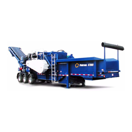
- Page 1 6700B Operator Safety Manual Portable Horizontal Grinder Serial Number: 31B-77-1535 and Up 81785C English...
- Page 2 Manual) are provided with the machine to 6700B own- herein. ers at no added cost. Peterson Pacific Corp. is an Astec Industries Co. • The 6700B Operator Safety Manual describes basic safety and operating information.
-
Page 3: Table Of Contents
Material Grinding ..... . 22 and operators of the Peterson 6700B Horizontal Grinder with Rotor and Rotor Bits ....22 information to produce quality, sized material in the safest, best manner known to us. - Page 4 O N T E N T S Removing Jammed Material ... . . 41 Lower the Landing Gear and Level the Ma- chine......64 Stored Energy Hazards.
- Page 5 O N T E N T S Alert Messages ..... . 92 Monthly Maintenance Schedule ..128 Display Failure Modes .
- Page 6 O N T E N T S 6 7 0 0 B G 8 1 7 8 5 C R I N D E R P E R A T O R A F E T Y A N U A L...
-
Page 7: About
BOUT ANUAL This 6700B Operator Safety Manual provides owners and operators of the Peterson 6700B Horizontal Grinder with information to produce quality, sized material in the safest, best manner known to us. It includes operating instruc- tions and safety instructions, and is shipped on board each new machine. -
Page 8: Safety Instructions
B O U T H I S A N U A L Safety Instructions Units of Weight and Measure Be sure to read all the safety information carefully to In this manual, U.S. customary units of weight and mea- avoid hazardous operations and to become aware of sure are stated first, followed by their SI (metric) values hazards that may arise during maintenance. -
Page 9: Limited Warranty
B O U T H I S A N U A L Limited Warranty This warranty is Peterson’s entire and only warranty to This warranty is null and void if other than genuine the Distributor and Distributor’s customers on resale Peterson parts are used. - Page 10 B O U T H I S A N U A L 6 7 0 0 B G 8 1 7 8 5 C R I N D E R P E R A T O R A F E T Y A N U A L...
-
Page 11: Machine Description
HAPTER ACHINE ESCRIPTION The 6700B includes material handling assemblies for feeding, grinding, and discharging the material. Supporting systems include the engine, clutch, hydraulics, and the electronic controls. Whole, irregular, or piece materials are fed into the Figure 1, Figure 2, and Figure 3 identify the major machine, where a rotor grinds the materials to a cus- machine parts and systems. - Page 12 3. Pivot Shaft, Compression Roll Housing/ 7. Air Compressor Anvil Housing 8. Engine Cover 4. IRS Cover Plate Figure 2: 6700B Horizontal Grinder, Top View Astec Industries Co. F05943 1. Main Hydraulic Tank 6. Fixed Ladder 2. Hydraulic Oil Cooler 7. Feed Chain Head Pulley 3.
-
Page 13: Machine Information
H A P T E R A C H I N E E S C R I P T I O N Machine Information Machine Serial Number Plate The machine serial number is engraved on a brass plate Information that identifies the machine and describes its mounted outside the hopper on the right (belt) side of operation, safety, maintenance, and repair is located on the machine (Figure 5). -
Page 14: Power Distribution
H A P T E R A C H I N E E S C R I P T I O N Power Distribution The power distribution system consists of the: • Diesel engine, which drives the machine’s hydrau- lic pumps and hydraulic clutch •... -
Page 15: Hydraulic System
H A P T E R A C H I N E E S C R I P T I O N While the engine is running, the clutch senses and com- pares input and output speeds for engaging, disengag- ing, and adjusting its performance. -
Page 16: Machine Controls
H A P T E R A C H I N E E S C R I P T I O N Machine Controls Machine controls are located on the control panel and on the remote transmitter. The control panel receives power from the battery, with circuit protection provided by a circuit breaker. -
Page 17: Control Panel
H A P T E R A C H I N E E S C R I P T I O N Control Panel The main operating controls (Figure 12) are mounted in a lockable cabinet on the radiator (left) side of the machine. - Page 18 H A P T E R A C H I N E E S C R I P T I O N Table 1: Control Panel Controls (Continued) Table 1: Control Panel Controls Icon Description Function Icon Description Function Discharge Conveyor Horn Press to signal to others in the Conveyor...
-
Page 19: Remote Transmitter Buttons
H A P T E R A C H I N E E S C R I P T I O N Remote Transmitter Remote Transmitter Buttons Table 2 describes how to use the remote transmitter You can use the on-machine control panel or the remote controls. -
Page 20: Transmitter Care And Handling
H A P T E R A C H I N E E S C R I P T I O N Transmitter Care and Handling Table 2: Remote Transmitter Buttons (Continued) • Clean the remote gently with a damp cloth. Do not Label Function dip the remote in water or spray it with a hose. -
Page 21: Hydraulic Control Levers
H A P T E R A C H I N E E S C R I P T I O N Hydraulic Controls Anvil Lift Push Buttons The anvil lift push buttons (Figure 15) are accessed The manually operated hydraulic controls are the from the belt (right) side platform. -
Page 22: Material Processing
H A P T E R A C H I N E E S C R I P T I O N Material Processing The feed chain moves material into the compression The gate is opened and closed by a hydraulic cylinder, roll. -
Page 23: Automatic Feed Control
H A P T E R A C H I N E E S C R I P T I O N Float Mode Shear Pins and Limit Switch When the feed system starts, the compression roll starts Shear pins (Figure 17) help protect the machine from in float mode. -
Page 24: Material Grinding
H A P T E R A C H I N E E S C R I P T I O N Material Grinding Anvil The anvil (Figure 18 and Figure 20) is the stationary, The machine grinds material by forcing it between the heavy, hardened steel bar that slices material into rotor bits and the anvil then between the bits and the smaller pieces when the rotor bits force material against... -
Page 25: Impact Release System
H A P T E R A C H I N E E S C R I P T I O N Impact Release System The Impact Release System (IRS) works by allowing the anvil housing to pivot upward when an ungrindable object strikes the anvil (Figure 20). - Page 26 H A P T E R A C H I N E E S C R I P T I O N The operator will typically set the IRS Trip Switch to Disabled at the display screen if the machine is to be operated in float mode.
- Page 27 H A P T E R A C H I N E E S C R I P T I O N F05877 Figure 22: Ungrindable Object Hits the Anvil F05878 Figure 23: Anvil Opens to Pass Ungrindable Object F05879 Figure 24: Anvil Relatches 8 1 7 8 5 C 6 7 0 0 B G...
-
Page 28: Irs Air Bag Option
H A P T E R A C H I N E E S C R I P T I O N IRS Air Bag Option IRS Set-Up System Option An optional air bag system (Figure 25 and Figure 26) The Impact Release System (IRS) latch set-up kit can be installed that provides closer control of anvil (Figure 27) will lift the anvil housing to allow techni-... -
Page 29: Magnetic Head Pulley Option
H A P T E R A C H I N E E S C R I P T I O N Material Discharge Conveyor Important Strong magnets can damage computer equipment Reduced material passes through the grates and falls and cause loss of data on magnetic storage onto the discharge conveyor belt (Figure 28). -
Page 30: Fire Prevention Equipment
H A P T E R A C H I N E E S C R I P T I O N Fire Prevention Air Brakes Air brakes are installed on the wheel axles with two air Equipment tanks on the front frame rails. The system connects to and is charged by the tractor’s brake system. -
Page 31: Water Sprinkler System
H A P T E R A C H I N E E S C R I P T I O N Water Sprinkler System Water Pump Sprayer The 6700B is equipped with a water sprinkler system The self-contained, gasoline-powered, high-pressure (Figure 31) to help suppress dust, which helps to pre- water pump sprayer system can help prevent fires and vent fire as dry materials pass through the grinding pro-... - Page 32 H A P T E R A C H I N E E S C R I P T I O N 6 7 0 0 B G 8 1 7 8 5 C R I N D E R P E R A T O R A F E T Y A N U A L...
-
Page 33: Working
HAPTER ORKING AFELY Safe working conditions require you to avoid machine and job-site hazards, to practice fire prevention, and to follow basic safety practices. This chapter will help you to work safely while operating and maintaining the 6700B grinder. How to Stay Safe Know the Machine: The following are parts of the machine designed to keep people safe during operation. -
Page 34: How This Chapter Is Organized
H A P T E R O R K I N G A F E L Y How this Chapter is Safety is Your Organized Responsibility Information in this chapter is organized under the fol- Make safety your first priority. lowing section headings: It is not possible for Peterson to be aware of all hazard- Safety First: This section covers basic safety responsi-... - Page 35 H A P T E R O R K I N G A F E L Y Use the Machine Only for its Designed Purpose The 6700B must be used only to do the work for which it was designed. Unsafe conditions may occur if the machine is operated under the following conditions: •...
-
Page 36: Job Site Safety
H A P T E R O R K I N G A F E L Y Job Site Safety Lift Properly: Avoid twisting or over-reaching, espe- Site conditions vary widely. Your machine may not be equipped with all devices mentioned. Local or federal cially when lifting or carrying heavy objects. -
Page 37: Grinder Job Site Hazards
H A P T E R O R K I N G A F E L Y Grinder Job Site Hazards Flying Objects Hazard The 6700B design minimizes risks of flying objects, but rocks, metals, knots, and other very hard objects in the WARNING feed material can sometimes be thrown as far as 300 ft While unfolding the conveyor, watch that no part... -
Page 38: Noise Hazard
H A P T E R O R K I N G A F E L Y Noise Hazard Hazard Zones Noise and limited visibility around the machine means Be aware of hazards that exist in the different areas all persons near the machine must pay attention to around the machine (see Figure 33 on page 37 and safety at all times. - Page 39 H A P T E R O R K I N G A F E L Y 5) Feed Chain Area: 4) Loader Operating Zone: Stay away from the feed chain when the engine is run- Watch for moving loaders. Loaders often drive fast and ning.
- Page 40 H A P T E R O R K I N G A F E L Y 6) Thrown Material Zone: • Keep the machine and the hazard zone aimed only into safe areas, such as: The thrown material zone (Figure 34) is where material •...
-
Page 41: Operating And Maintaining The Machine Safely
H A P T E R O R K I N G A F E L Y Operating and Maintaining the Machine Safely This section describes the hazards of operating and maintaining the machine and identifies the safety devices for reducing risk of injury. Emergency Stop CAUTION Know the location of the Emergency Stop switch... -
Page 42: Automatic Idle/Automatic Shutdown
H A P T E R O R K I N G A F E L Y Machine Lockout/Tagout Use the Battery Disconnect Switch lockout device (Figure 37) to keep the electrical control system turned off under the following conditions: •... -
Page 43: Removing Jammed Material
H A P T E R O R K I N G A F E L Y ◆ To lock out or tag out the machine: Jams between the rotor and grates may be time-consum- ing to clear. Access to the area can be gained by opening 1. -
Page 44: Flying Debris
H A P T E R O R K I N G A F E L Y Compression Roll Hazards A safety locking stop is provided on each side of the machine to support the compression roll housing in its Your awareness of the compression roll hazards is lifted position. -
Page 45: Precautions For Operating The Grinder
H A P T E R O R K I N G A F E L Y Grinding Area Hazards WARNING A falling compression roll housing can cause The grinding area is where material reduction work is severe injury or death. done. -
Page 46: Lowering Or Raising The Tailgate
H A P T E R O R K I N G A F E L Y Entering the Hopper WARNING Always do the recommended daily inspection and maintenance as described in the 6700B Maintenance Manual. Replace worn bits and fas- WARNING teners. -
Page 47: Entering The Rotor Discharge Area
H A P T E R O R K I N G A F E L Y Entering the Rotor Discharge Area The rotor discharge area (Figure 43) is accessible by a side access door (Figure 42) and from the top of the machine when the anvil housing has been raised. -
Page 48: Sudden Upward Movement
H A P T E R O R K I N G A F E L Y Anvil Housing Hazards WARNING Always properly set the safety pin any time that: Your awareness of the anvil housing hazards is essential • Maintenance, inspection, or repair work is to be to your safety. -
Page 49: Feed Chain Hazards
H A P T E R O R K I N G A F E L Y Conveyor and Chain Hazards Feed Chain Hazards Observe the following feed chain and discharge con- veyor safety rules: • Keep all guards in place during operation. Replace any guards and close any access doors or openings that were used during maintenance. -
Page 50: Discharge Conveyor Hazards
H A P T E R O R K I N G A F E L Y Falling Objects Hazard Discharge Conveyor Hazards Any raised or overhead device has stored energy and can fall if its supports fail or are caused to fail. Do not place yourself under any object that can fall or move caused by loss of hydraulic pressure or mechani- cal support. -
Page 51: Magnetic Hazards
H A P T E R O R K I N G A F E L Y Magnetic Hazards CAUTION The magnetic head pulley and cross-belt con- veyor contain very strong magnets, which can be dangerous to anyone wearing a pacemaker or other implanted system that is sensitive to mag- nets. -
Page 52: Fire Prevention And Suppression
H A P T E R O R K I N G A F E L Y Fire Prevention and Suppression Pre-Startup Fire Prevention The best way to reduce the risk of fire is to keep the machine clean and well main- tained. -
Page 53: Fire Prevention After Shutdown
H A P T E R O R K I N G A F E L Y Fire Prevention After Fire Prevention Equipment Shutdown Extinguisher The red fire extinguisher (Figure 48) shipped with the WARNING machine is mounted on the frame. The extinguisher After shutdown, look carefully for burning or must be inspected annually and pressure-tested on a smoldering material. -
Page 54: Water Sprinkler System
H A P T E R O R K I N G A F E L Y ◆ To use the water sprinkler system: Remember that a clean machine is a safer one. If you control and prevent accumulation of combustible mate- •... - Page 55 H A P T E R O R K I N G A F E L Y ◆ To take the system out of service: 1. Drain the tank 2. Drain the pump 3. Drain the hose. Keep the engine cover in place during travel and when the machine is in storage.
-
Page 56: Safety Labels
H A P T E R O R K I N G A F E L Y Safety Labels Hazard alert, instruction, and safety decals are attached to the 6700B for your safety. Decals remind operators and other workers not to expose themselves to risks of crushing, pinching, or trapping caused by rotating, mov- ing, or unguarded parts and other hazards. - Page 57 H A P T E R O R K I N G A F E L Y 63467-10 64941-10 Figure 57: Warning: High Pressure Fluid Figure 60: Warning: Landing Gear/Crushing Hazard 65419-10 64461-10 Figure 58: Warning: Do Not Operate Without Guards Figure 61: Warning: Confined Space 64462-10 65672-10...
- Page 58 H A P T E R O R K I N G A F E L Y 67264-10 68991-10 Figure 66: Warning: Moving Conveyor Figure 63: Warning: Flying Debris WARNING Risk of serious injury or death! Do not work on or maintain the machine while the engine is running.
- Page 59 H A P T E R O R K I N G A F E L Y 73330-10 73333-10 Figure 69: Warning: Lock Out/Tag Out Figure 71: Warning: Shock and Electrocution Hazard 73337-10 Figure 72: Insert Safety Pin Right of Here SAFETY PIN 73338-01 73338-01...
- Page 60 H A P T E R O R K I N G A F E L Y 75713-10 Figure 76: Warning: Avoid Pinch Points 74164-10 74161-10 Figure 74: Danger: Avoid Fires. Hot Metals Figure 77: Caution: Hot Exhaust Surfaces WARNING FLYING MATERIAL.
- Page 61 H A P T E R O R K I N G A F E L Y 73779-10 Figure 83: Danger: Always Use a Safety Locking Pin 79723-10 Figure 80: Danger: Fire Hazard, Wood and Fluids 79728-10 Figure 84: Danger: Fire Hazard, No Smoking 74162-10 Figure 81: Warning: Avoid Inhaling Diesel Exhaust 74247...
- Page 62 H A P T E R O R K I N G A F E L Y 84228-10 Figure 89: Danger: Keep Back! Raised Compression Roll 79725-10 Figure 86: Danger: Fire Hazard, Hot Engine Exhaust IRS latch is spring loaded and can move without warning.
-
Page 63: Warnings During Maintenance
H A P T E R O R K I N G A F E L Y 85180-10 WARNING Figure 92: Warning: Thrown Material Hazard Zone Crushing or pinching hazard. A damaged or missing guard, safety device, or decal can expose operators to risk of injury or death. - Page 64 H A P T E R O R K I N G A F E L Y WARNING Crushing or pinching hazard. Keep hands clear of the moving parts of the anvil housing while closing the housing after changing grates or doing other maintenance.
-
Page 65: Operating The 6700B
HAPTER 6700B PERATING THE This Chapter provides instructions for operating the grinder through three phases of activity: getting started, running the grinder, and finishing up. Getting Started or hard rocks strike hard enough to move the single pivot shaft. If the feed material contains a lot of scrap, use the ◆... -
Page 66: Position The Machine
6 7 0 0 B H A P T E R P E R A T I N G T H E Position the Machine 3. Use the L and the R ANDING IGHT hydraulic control levers to lower ANDING the landing gear. -
Page 67: Pre-Startup Inspection
6 7 0 0 B H A P T E R P E R A T I N G T H E Pre-Startup Inspection 5. Check fluid levels for the engine and the hydraulic system: Look over the entire machine carefully before starting •... - Page 68 6 7 0 0 B H A P T E R P E R A T I N G T H E LOW IDLE ENGINE STOPPED F05902 Figure 96: Engine Oil Level Dipstick • Engine air primary filters—Clean daily. • Fuel/Water Separator—Check for water daily (Figure 97).
- Page 69 6 7 0 0 B H A P T E R P E R A T I N G T H E 1 in. 2 in. F05991 Figure 101: Hydraulic Suction Line Valves (3) F05669 Figure 100: Sight/Temperature Gauge on Hydraulic Oil Tank Important Make sure the valves underneath the tank are open Important...
-
Page 70: Setting Up For Operation
6 7 0 0 B H A P T E R P E R A T I N G T H E Setting Up for Operation Raise or Lower the Tailgate If your machine is equipped with a tailgate, lower or raise it at this time. -
Page 71: Connect The Water Sprinkler
6 7 0 0 B H A P T E R P E R A T I N G T H E Connect the Water Sprinkler 3. Close the air bags pressure release valve (Figure 105) to allow the air bags to inflate. The water sprinkler system helps to control dust and 4. -
Page 72: Start The Engine
6 7 0 0 B H A P T E R P E R A T I N G T H E Start the Engine WARNING Anyone not involved with operating the 6700B should leave the area. Allow only qualified per- sonnel experienced in operating industrial equipment of this type to operate the machine. -
Page 73: Set The Slide Gate
6 7 0 0 B H A P T E R P E R A T I N G T H E Set the Slide Gate Unfold the Conveyor Depending on the material and grinding conditions, you Unfold the conveyor before running the machine for may want to close or open the slide gate. -
Page 74: Operating The Grinder
6 7 0 0 B H A P T E R P E R A T I N G T H E Operating the How to Begin Processing Material Grinder ◆ Starting to process material involves the The operation of the feed chain, the discharge conveyor, following steps: the compression roll, and the grinder assembly are coor- 1. -
Page 75: Start The Feed System
6 7 0 0 B H A P T E R P E R A T I N G T H E Inspect Before Grinding Important If several attempts to engage the clutch fail, wait 5 Before placing material into the hopper: min to allow the clutch to cool down, then shut ❏... -
Page 76: How To Control The Machine While Grinding
6 7 0 0 B H A P T E R P E R A T I N G T H E How to Control the Machine Reversing the Feed System While Grinding Manual Reversal Controlling the grinder requires understanding the fol- ◆... -
Page 77: Operating The Compression Roll
6 7 0 0 B H A P T E R P E R A T I N G T H E Compression roll raised too high: WARNING If material in the feed pushes the compression roll too In “land-clearing mode”, the compression roll is held higher than normal, raising the risk that high, the feed system will stop and run in the reverse material might fly out and injure persons in the... -
Page 78: Monitoring Machine The While Grinding
6 7 0 0 B H A P T E R P E R A T I N G T H E Monitoring Machine the While 2. Press R on the remote transmitter. Raise the compression roll to its maximum height. Grinding 3. - Page 79 6 7 0 0 B H A P T E R P E R A T I N G T H E 4. Check the Feed Chain Tension. Feed chains 7. Check the Compression Roll Seals (Debris Cov- stretch as they wear. At the middle of the hopper, ers) (Figure 111).
- Page 80 6 7 0 0 B H A P T E R P E R A T I N G T H E ◆ To inspect the grinding area parts: The middle of the grates wear more than the sides. Details on checking and adjusting the following items 7.
- Page 81 6 7 0 0 B H A P T E R P E R A T I N G T H E 9. Check the Bit-to-Anvil Gap. Make sure the gap between the anvil and bits is 3/8 to 3/4 in. (1–2 cm) (Figure 117).
- Page 82 6 7 0 0 B H A P T E R P E R A T I N G T H E 11. Check the Bits. Check the bits every day for condi- Bit Wear Patterns: tion and tightness. Worn or broken bits produce poor quality output, slow down production, use more power, and are a safety hazard.
- Page 83 6 7 0 0 B H A P T E R P E R A T I N G T H E ◆ To place the machine back into service: 1. Close the access door. 2. Restart the engine when ready for operation. See “Start the Engine”...
-
Page 84: Finishing Up
6 7 0 0 B H A P T E R P E R A T I N G T H E Finishing Up 7. Run the engine at low idle for 5 minutes to cool it down. 8. Stop the engine—Turn the E Start/Stop NGINE At the end of a work shift, clean and care for the... -
Page 85: After-Shutdown Inspection
6 7 0 0 B H A P T E R P E R A T I N G T H E After-Shutdown Inspection Securing the Machine Preventing unauthorized use of the machine protects it against accidental damage and theft and reduces the risk DANGER of injury to untrained people. -
Page 86: Fluid Recommendations
6 7 0 0 B H A P T E R P E R A T I N G T H E Fluid Main Hydraulic System • Hydraulic oil AW46 ASTM D or equivalent ISO- Recommendations VG46 • For very cold weather, hydraulic oil AW32 or equivalent For fluid recommendation details and additional speci- fications, refer to the original equipment manufacturer’s... - Page 87 6 7 0 0 B H A P T E R P E R A T I N G T H E Starting the Air Compressor WARNING Before starting the air compressor, read and understand the safety and start-up information in the Honda Owner’s Manual.
- Page 88 6 7 0 0 B H A P T E R P E R A T I N G T H E 6 7 0 0 B G 8 1 7 8 5 C R I N D E R P E R A T O R A F E T Y A N U A L...
-
Page 89: Displaying Machine Information
HAPTER ISPLAYING ACHINE NFORMATION The Peterson Adaptive Control System provides several display screens for entering system settings and for check- ing on machine operation. F05754 Figure 121: Peterson Display Module Surrounding the display screen are the following 11 but- screen. For example, pressing F5 on the Machine Status tons and a rotary encoder knob for input and menu Page takes you to “Information Page”... - Page 90 H A P T E R I S P L A Y I N G A C H I N E N F O R M A T I O N Adjusting the Display 2. Esc or Back Button (Left Arrow): The Esc button always returns you to the previous display page.
-
Page 91: Machine Status And Options
H A P T E R I S P L A Y I N G A C H I N E N F O R M A T I O N Machine Status and Options Machine Status Page F05754 Figure 122: Machine Status Page The Machine Status Page (Figure 122) is the first page •... - Page 92 H A P T E R I S P L A Y I N G A C H I N E N F O R M A T I O N • Electrical Page (Press F3) see Figure 135 on page 109 •...
-
Page 93: Machine Alert Notices
H A P T E R I S P L A Y I N G A C H I N E N F O R M A T I O N Machine Alert Notices F05755 Figure 123: Machine Alert Notice (Alarm Example) Sometimes a machine alert message appears. -
Page 94: Alert Messages
H A P T E R I S P L A Y I N G A C H I N E N F O R M A T I O N Alert Messages machine component that needs attention. The message describes the alert and in some cases provides an action Alert messages notify you about operating conditions of to take. - Page 95 H A P T E R I S P L A Y I N G A C H I N E N F O R M A T I O N Table 7: Alert Messages from Machine Operation Alert Level Message Heading Message Effect Critical...
- Page 96 H A P T E R I S P L A Y I N G A C H I N E N F O R M A T I O N Table 8: Alert Messages from the CAT Engine Alert Level Message Heading Message Effect SPN/FMI...
- Page 97 H A P T E R I S P L A Y I N G A C H I N E N F O R M A T I O N Table 8: Alert Messages from the CAT Engine (Continued) Alert Level Message Heading Message Effect...
-
Page 98: Display Failure Modes
H A P T E R I S P L A Y I N G A C H I N E N F O R M A T I O N Display Failure Modes Table 10: Failure Modes for CAN Interface The following tables list the built-in failure modes from the Peterson display modules. - Page 99 H A P T E R I S P L A Y I N G A C H I N E N F O R M A T I O N Table 12: Failure Modes for VREF Table 14: Failure Modes in Current Mode Failure Mode Effect Failure Mode...
-
Page 100: Expansion Module Error Codes
H A P T E R I S P L A Y I N G A C H I N E N F O R M A T I O N Expansion Module Error Codes The machine uses two IQAN expansion modules mounted in the control panel box (Figure 125) to help control the operating system. -
Page 101: Machine Options Page
H A P T E R I S P L A Y I N G A C H I N E N F O R M A T I O N Machine Options Page F05936 Figure 126: Machine Options Page The Machine Options page (Figure 126) provides access to other pages. -
Page 102: Spiral Splitter Page
H A P T E R I S P L A Y I N G A C H I N E N F O R M A T I O N Spiral Splitter Page F05975 Figure 127: Spiral Splitter Page The Spiral Splitter page (Figure 127) allows you to D—Splitter Direction function: operate the (optional) spiral splitter. -
Page 103: Engine Information
H A P T E R I S P L A Y I N G A C H I N E N F O R M A T I O N Engine Information Engine Page F05758 Figure 128: Engine Page The Engine Page (Figure 128) displays the following: •... -
Page 104: Engine Fuel Usage Page
H A P T E R I S P L A Y I N G A C H I N E N F O R M A T I O N Engine Fuel Usage Page F05435 Figure 129: Engine Fuel Usage Page Use the Engine Fuel Usage Page (Figure 129) to calcu- late your fuel used during a set period of time, starting whenever you want. -
Page 105: Engine Parameters
H A P T E R I S P L A Y I N G A C H I N E N F O R M A T I O N Engine Parameters F05439 Figure 130: Engine Parameters The Engine Parameter Page (Figure 130) shows the nor- mal operating parameters for engine load and system voltage. -
Page 106: Radiator Fan Page
H A P T E R I S P L A Y I N G A C H I N E N F O R M A T I O N Radiator Fan Page F05966 Figure 131: Radiator Fan Page The Radiator Fan page (Figure 131) allows you to mon- •... -
Page 107: Clutch Information
H A P T E R I S P L A Y I N G A C H I N E N F O R M A T I O N Clutch Information Clutch Page F05917 Figure 132: Clutch Page The Clutch page (Figure 132) displays the status of the •... -
Page 108: Clutch Faults
H A P T E R I S P L A Y I N G A C H I N E N F O R M A T I O N Clutch Faults • Clutch Disengaged/Inhibited Due to Coil Fault This message shows that there is a problem in the coil or coil wires. -
Page 109: Hydraulics
H A P T E R I S P L A Y I N G A C H I N E N F O R M A T I O N Hydraulics Hydraulic System Page F05967 Figure 133: Hydraulic System page The Hydraulic System page (Figure 133) shows the fol- Press F4 to access the Feed System page. -
Page 110: Hydraulic Fan Page
H A P T E R I S P L A Y I N G A C H I N E N F O R M A T I O N Hydraulic Fan Page F05965 Figure 134: Hydraulic Fan Page The Hydraulic Fan page (Figure 134) shows the status •... -
Page 111: Electrical Information
H A P T E R I S P L A Y I N G A C H I N E N F O R M A T I O N Electrical Information Electrical System Page F05964 Figure 135: Electrical System Page The Electrical System page (Figure 135) monitors sys- tem voltage. -
Page 112: Electrical Outputs Page
H A P T E R I S P L A Y I N G A C H I N E N F O R M A T I O N Electrical Outputs Page F05963 Figure 136: Electrical Outputs Page The Electrical Outputs page (Figure 136) monitors the Table 16 lists the variable, range, and factory preset val- electrical outputs from the Peterson display system to... - Page 113 H A P T E R I S P L A Y I N G A C H I N E N F O R M A T I O N Table 16: Electrical Outputs (Continued) Subsystem Expected Output Range Variable 450-850 Forward Hydraulic Fan...
-
Page 114: Electrical Inputs Page
H A P T E R I S P L A Y I N G A C H I N E N F O R M A T I O N Electrical Inputs Page F05962 Figure 137: Electrical Inputs Page The Electrical Inputs page (Figure 137) shows the elec- trical inputs from transducers and limit switches to the Peterson display operating system. - Page 115 H A P T E R I S P L A Y I N G A C H I N E N F O R M A T I O N Table 17: Electrical Inputs to Peterson Display System Sensor Raw Value Range Scaled Value Error Value...
-
Page 116: Remote Control Inputs Page
H A P T E R I S P L A Y I N G A C H I N E N F O R M A T I O N Remote Control Inputs Page F05974 Figure 138: Remote Control Inputs Page ◆... -
Page 117: Control Panel Inputs Page
H A P T E R I S P L A Y I N G A C H I N E N F O R M A T I O N Control Panel Inputs Page F05976 Figure 139: Control Panel Inputs Page The Control Panel Inputs page (Figure 139) checks that When a button is pressed on the control panel, the cor- the controller receives proper inputs when someone... -
Page 118: Feed System Information
H A P T E R I S P L A Y I N G A C H I N E N F O R M A T I O N Feed System Information Feed System Page F05756 Figure 140: Feed System Page The Feed System Page (Figure 140) shows the current •... - Page 119 H A P T E R I S P L A Y I N G A C H I N E N F O R M A T I O N Feed Information Discharge Conveyor Information • Direction arrows show the direction that the feed •...
-
Page 120: Peterson Adaptive Control System
H A P T E R I S P L A Y I N G A C H I N E N F O R M A T I O N Peterson Adaptive Control System Automatic control of the feed and compression systems compression roll, reverses (maximum reverse speed is is known as the Peterson Adaptive Control System. -
Page 121: Maintenance And Troubleshooting
H A P T E R I S P L A Y I N G A C H I N E N F O R M A T I O N Maintenance and Troubleshooting Information Page F05968 Figure 141: Information Page The Information page (Figure 141) shows the machine serial number and Peterson contact information. -
Page 122: Machine Performance Page
H A P T E R I S P L A Y I N G A C H I N E N F O R M A T I O N Machine Performance Page F05753 Figure 142: Machine Performance Page The Machine Performance Page (Figure 142) displays information for the current day. -
Page 123: Troubleshooting Menu
H A P T E R I S P L A Y I N G A C H I N E N F O R M A T I O N Troubleshooting Menu (Page 1) F05977 Figure 143: Troubleshooting Menu (Page 1) The Troubleshooting Menu page 1 (Figure 143) has menu items that link to pages that have basic trouble- shooting instructions. -
Page 124: Troubleshooting Menu
H A P T E R I S P L A Y I N G A C H I N E N F O R M A T I O N Troubleshooting Menu (Page 2) F05978 Figure 144: Troubleshooting Menu (Page 2) The Troubleshooting Menu page 2 (Figure 144) has menu options that link to troubleshooting-related pages. -
Page 125: Anti-Bridge Page
H A P T E R I S P L A Y I N G A C H I N E N F O R M A T I O N Anti-Bridge Page F05761 Figure 145: Anti-Bridge Page ◆ To access the Anti-Bridge Page: •... -
Page 126: Compression Roll Stall Bump Page
H A P T E R I S P L A Y I N G A C H I N E N F O R M A T I O N Compression Roll Stall Bump Page F05760 Figure 146: Compression Roll Stall Bump Page ◆... -
Page 127: Maintenance Schedule
H A P T E R I S P L A Y I N G A C H I N E N F O R M A T I O N Maintenance Schedule F05969 Figure 147: Maintenance Schedule ◆ To reset the engine oil change timer: The Maintenance Schedule page (Figure 147), accessed from the Information Page, displays the following •... -
Page 128: Daily Maintenance Schedule
H A P T E R I S P L A Y I N G A C H I N E N F O R M A T I O N Daily Maintenance Schedule F05746 Figure 148: Daily Maintenance Schedule The Daily Maintenance Schedule (Figure 148) provides a list of pre-startup checks. -
Page 129: Weekly Maintenance Schedule
H A P T E R I S P L A Y I N G A C H I N E N F O R M A T I O N Weekly Maintenance Schedule F05752 Figure 149: Weekly Maintenance Schedule The Weekly Maintenance Schedule (Figure 149) lists suggested maintenance procedures for your machine. -
Page 130: Monthly Maintenance Schedule
H A P T E R I S P L A Y I N G A C H I N E N F O R M A T I O N Monthly Maintenance Schedule F05750 Figure 150: Monthly Maintenance Schedule The Monthly Maintenance Schedule (Figure 150) lists suggested maintenance procedures for your machine. -
Page 131: Peterson Setup Menus
H A P T E R I S P L A Y I N G A C H I N E N F O R M A T I O N Peterson Setup Menus Main Setup Screen F05569 Figure 151: Main Setup Screen The Main setup screen (Figure 151) is available by pressing the Setup Button (see Figure 121 on page 87). -
Page 132: Adjust Setup Menu
H A P T E R I S P L A Y I N G A C H I N E N F O R M A T I O N Adjust Setup Menu F05972 Figure 152: Adjust Page 1 C’Roll to Feed Ratio The Adjust setup menu (Figure 152) is accessible from the Main setup page. - Page 133 H A P T E R I S P L A Y I N G A C H I N E N F O R M A T I O N Compression Roll Bump Max height—changes the Stop to REV spread—changes the RPM spread between maximum height at which the Compression Roll stall the stop and reverse points of the adaptive feed system bump feature is activated...
- Page 134 H A P T E R I S P L A Y I N G A C H I N E N F O R M A T I O N • 250 hours is the default (50 hours minimum, 500 hours maximum) HYD oil change freq—changes how often the hydraulic oil is to be changed...
-
Page 135: Measure Setup Menu
H A P T E R I S P L A Y I N G A C H I N E N F O R M A T I O N Measure Setup Menu F05763 Figure 153: Measure Setup Menu The Measure setup menu (Figure 153) is accessible from the Main setup screen. -
Page 136: Preferences Setup Menu
H A P T E R I S P L A Y I N G A C H I N E N F O R M A T I O N Preferences Setup Menu F05568 Figure 154: Preferences Setup Menu The Preferences setup menu (Figure 154) is accessible from the Main setup screen. -
Page 137: Info Setup Menu
H A P T E R I S P L A Y I N G A C H I N E N F O R M A T I O N Info Setup Menu F05973 Figure 155: Info Setup Menu The Info setup menu (Figure 155) is accessible from the •... - Page 138 H A P T E R I S P L A Y I N G A C H I N E N F O R M A T I O N 1 3 6 6 7 0 0 B G 8 1 7 8 5 C R I N D E R P E R A T O R...
-
Page 139: Reparing For Ransport
HAPTER REPARING FOR RANSPORT Before loading the 6700B for transport, the machine must be properly prepared. Roll Up the Material Deflector ◆ To prepare the machine for transport: 1. Check for loose items and debris. 1. Roll up the rubber deflector (Figure 156). 2. -
Page 140: Fold The Discharge Conveyor
H A P T E R R E P A R I N G F O R R A N S P O R T Fold the Discharge Conveyor Important The machine could be damaged if the roll is not Before transporting the machine over roads or high- fully down onto the down stops. -
Page 141: Attach The Machine To The Towing Vehicle
H A P T E R R E P A R I N G F O R R A N S P O R T Attach the Machine to the Towing Vehicle Always load and unload the machine on a firm, level surface. -
Page 142: Secure The Machine
H A P T E R R E P A R I N G F O R R A N S P O R T Secure the Machine Open and Secure the Radiator Screen Stow and Lock the Folding Ladder Important The specified travel width is achieved only when Lock the folding ladder in its upright position over the... -
Page 143: Transportation Weights And Dimensions
H A P T E R R E P A R I N G F O R R A N S P O R T Transportation Weights and Dimensions F04500 Figure 162: Transportation Dimensions Table 18: Transportation Dimensions Table 19: Transportation Weights Total machine weight 90,000 lb. - Page 144 H A P T E R R E P A R I N G F O R R A N S P O R T 1 4 2 6 7 0 0 B G 8 1 7 8 5 C R I N D E R P E R A T O R A F E T Y...
- Page 145 NDEX Boost pressure ......101 Breather ........13 Adaptive control system .
- Page 146 N D E X Discharge conveyor ......27 status and data ......117 Failure modes .
- Page 147 N D E X Grinding ........22 Key, padlock .
- Page 148 N D E X Nozzles ........34 behaviors .
- Page 149 N D E X Toe protection ....... 34 Torque ........6 Torque, ft-lb .
- Page 150 N D E X 1 4 8 6 7 0 0 B G 8 1 7 8 5 C R I N D E R P E R A T O R A F E T Y A N U A L...
Need help?
Do you have a question about the Peterson 6700B and is the answer not in the manual?
Questions and answers