
Subscribe to Our Youtube Channel
Related Manuals for Muirhead 3565

Summary of Contents for Muirhead 3565
- Page 1 PRODUCT MANUAL ENGINE PROTECTION SYSTEM 6-FUNCTION TO SUIT WATER COOLED ENGINES Part No. 3565...
- Page 2 LEGAL NOTICE You acknowledge that this document is protected under copyright law and Remote Control Technologies Pty Ltd or its related bodies corporate (“RCT”) owns the copyright in this document or otherwise have permission or licence from the relevant owner to use certain specific works.
-
Page 3: Table Of Contents
Contents ⚠ Caution Consult the specifications data sheet on page 23 prior to installing the product.—incorrect fitment will void the manufacturer’s warranty. General Safety Warnings Personal Safety Machine Product Product Overview Features and Functions Operation and Use Control Unit Wiring Connections Inputs −... - Page 4 Parts List Decals supplied with the Product Wiring Loom to suit 3565 Control Unit Coolant Level Sensors Pressure Switches to suit Engine Oil Pressure Applications Pressure Switches to suit Temperature Monitoring Applications Flow Switches to suit Coolant Flow Applications Oil/Fuel Level Switches to suit the Oil Level Monitoring Applications.
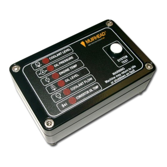
- Page 5 Table of Figures Figure 1 Muirhead Engine Protection System, part number 3565 ..............7 ® Figure 2 EPS control unit external view ......................8 Figure 3 EPS label, water cooled ........................15 Figure 4 Drawing 236s – EPS protection system water-cooled external wiring diagram ....... 17 Figure 5 Drawing 478i –...
-
Page 6: General Safety Warnings
General Safety Warnings Personal Safety ■ Everyone is responsible for safety. ■ The installer/service personnel should be trained and authorized to complete the required work. ■ Ensure that the machine is safely isolated during installation and testing to protect all personnel. ■... -
Page 7: Product Overview
Engine Protection System, part number 3565 ® The Muirhead Engine Protection system (EPS), part number 3565, is designed to monitor almost any alarm ® condition on virtually any machine. This system has been designed to monitor six inputs including an AC input for detecting coolant loss and three digital outputs. -
Page 8: Operation And Use
Operation and Use Control Unit Electronic circuitry within the EPS control unit checks the state of the switches and sensors, and then activates the corresponding alert indicator and control outputs when an alarm condition is sensed. The EPS label displays the alert indicator or function that has faulted. A test switch on the front of the EPS control unit allows the operator to simulate a fault and test the complete system. -
Page 9: Inputs
Inputs The following input functions show the factory defaults with all inputs and outputs being configurable. Refer to document number P0021 for advanced programming information. Contact your local RCT branch or distributor for a copy of the document or for more information. Function 1 This input is configured to have a five-second delay prior to pulsing the alert indicator and activating the alarm. -
Page 10: Outputs
Outputs Alarm Control Output This circuit is activated as soon as an alert indicator is active. This output remains active until the EPS control unit has no alert indicator active or the key is switched off. This output is disabled until a start signal is sensed. This allows servicing to be carried out with the key on without the alarm sounding. -
Page 11: Installation Guide
4. Install the sensors/ switches (see below for more detail). All sensors/ switches should be installed using a suitable thread sealant. Options If a Muirhead Idle Timer is fitted, the machine will return to idle at once. ® ... -
Page 12: Coolant Level Sensor - Function 1
(OEM) oil pressure switch as a guide for location. Fit the oil pressure switch using thread sealant, being careful not to over tighten. Note T-pieces are available in most thread types to enable both the OEM and Muirhead Oil Pressure Switches to ®... -
Page 13: Coolant Temperature Switch - Function 3
Coolant Temperature Switch – Function 3 The coolant temperature switch should be installed on the engine side of the thermostat control. It is imperative that the switch sensing area (bulb) be immersed in coolant. Install the switch using thread sealant. Note Care should be taken when selecting a mounting port to allow sufficient depth for the bulb. -
Page 14: Coolant Flow Switch - Function 5
Coolant Flow Switch – Function 5 The coolant flow switch monitors the coolant flow in the engine while it’s operating; the coolant flow switch is installed as specified by the OEM. The switch is suitable for the following Caterpillar engines: ■... -
Page 15: Engine Protection System Labelling
Engine Protection System Labelling Water-Cooled FUNCTION 1 Typically used for coolant level monitoring FUNCTION 2 Typically used for engine oil pressure monitoring OIL PRESSURE PROTECTION SYSTEMS FUNCTION 3 Typically used for engine temperature monitoring ENGINE TEMP FUNCTION 4 Typically used for oil level monitoring OIL LEVEL SYSTEM... -
Page 16: Alert Function Identification Labels
Alert Function Identification Labels Part No, Label Part No. Label 5636 6143 0427 1526 1372 5630 5629 5635 0426 5634 0437 5637 0428 1413 0442 4352 0453 5638 0486 5633 3465 4350 3144 5631 5785 5632 5780 4348 5782 1411 5784 4349 5779... -
Page 17: Typical Engine Protection System Schematic To Suit 6-Function Water-Cooled Engine (236S)
GROUND to RCT, on demand. (RECOMMENDED 10AMP SWITCH PROTECTION) ENGINE PROTECTION SYSTEM 6 FUNCTION WATER COOLED EXTERNAL WIRING PART 3565 WIRE LEGEND STOCK MH-EPS-6 CODE BK - BLACK PK - PINK BU - BLUE PU - PURPLE DATE 1/11/05 APPD... -
Page 18: Calibration
Calibration Not applicable Service Information Service Schedule The manufacturer recommends that the following service procedure should be performed at each machine’s scheduled service interval. Service Procedure 1. Perform a visual inspection and include the following: a) Control unit b) Wiring connections and looms c) All switches and sensors as below d) Engine fluids 2. -
Page 19: Coolant Flow Switch
Coolant Flow Switch Every 2000 hours or six months 1. It will be necessary to remove the switch for testing. 2. Remove switch and plug hole to prevent fluid loss. 3. Inspect the switch for physical damage. 4. Move the paddle to the coolant no flow position. 5. -
Page 20: Coolant Level Sensor
Coolant Level Sensor Every 250 hours or during machine scheduled service 1. Turn the ignition switch to the ON position and verify the coolant level alert indicator is not illuminated. 2. Disconnect the wire from the coolant level sensor. 3. Verify that the coolant level alert indicator is now illuminated. 4. -
Page 21: Parts List
Wiring Loom to suit 3565 Control Unit Part No. Description 5994 Loom 10 m to Suit 3747 & 3565 EPS Control unit Coolant Level Sensors Part No. Description 2006... -
Page 22: Pressure Switches To Suit Temperature Monitoring Applications
Pressure Switches to suit Temperature Monitoring Applications Part No. Description 1764 Temperature Switch 212 °F / 100 °C, N/C, 2 Terminal, 3/8 NPT 1765 Temperature Switch 220 °F / 104 °C, N/C, 2 Terminal, 3/8 NPT 1766 Temperature Switch 230 °F / 110 °C, N/C, 2 Terminal, 3/8 NPT 1767 Temperature Switch 250 °F / 120 °C, N/C, 2 Terminal, 3/8 NPT 1768... -
Page 23: Technical Specifications
Technical Specifications ⚠ Caution Read prior to the installation of the product. Incorrect fitment will void the manufacturer’s warranty. Dimensions, control unit only: Length: 125 mm | Width: 40 mm | Height/Depth: 80 mm Dimensions, boxed for freight: Length: 140 mm | Width: 140 mm | Height/Depth: 70 mm Weight, control unit only: 0.65 kg Weight, including harness /... -
Page 24: Compliance And Standards
Compliance and Standards Troubleshooting Troubleshooting the engine protection system requires more information from the manual that is supplied with the Muirhead EPS system. A typical engine protection schematic guide is provided in this manual. ® During troubleshooting, inspect all components and connectors before any components are replaced. If connectors are not tight and clean, they can cause intermittent or permanent electrical faults. -
Page 25: Glossary
Glossary Amp (Ampere) Minimum alternating current millimetres Advanced Management System Milliwatts Auxiliary Output Not Applicable Controller Area Network Normally Closed ControlMaster Input Output PCB Normally Open CMIO ® ControlMaster Receiver Original Equipment Manufacturer ® ControlMaster Transmitter Outputs ® ControlMaster ® 2200 Remote Set Output CM2200... -
Page 26: Warranty
Warranty Please see the RCT standard warranty, available on our website - www.rct-global.com. 26 | 28 M0160.docx | Rev 1.3 | Modified on 19/05/2020 | © Remote Control Technologies Pty Ltd... -
Page 27: Appendix
UNCONTROLLED DOCUMENT Machine may return to idle or shutdown on fault SCALE 3rd ANGLE PROJECTION (3565)(3747) www.rct.net.au COPYRIGHT - ALL RIGHTS RESERVED (9200)(9301) This drawing is the property of REMOTE CONTROL TECHNOLOGIES PTY LTD (RCT), and is not to be copied or used in whole or in part for any purpose without the express authority of RCT. - Page 28 Discover more: www.rct-global.com sales@rct-global.com AUSTRALIA: +61 (0) 8 9353 6577 AFRICA: +27 (0) 83 292 4246 CANADA: +1 705 590 4001 RUSSIA / CIS: +7 (910) 411 11-74 SOUTH AMERICA: +56 3 5229 9409 USA: +1 801 938 9214 28 | 28 M0160.docx | Rev 1.3 | Modified on 19/05/2020 | ©...
Need help?
Do you have a question about the 3565 and is the answer not in the manual?
Questions and answers