
Related Manuals for Denso CRS


Summary of Contents for Denso CRS
- Page 1 Diesel Injection Pump SERVICE MANUAL COMMON RAIL SYSTEM (CRS) OPERATION September, 2007 00400534E...
- Page 2 © 2007 DENSO CORPORATION All Rights Reserved. This book may not be reproduced or copied, in whole or in part, without the written permission of the publisher.
- Page 3 Revision History Revision History Date Revision Contents 2007. 09 • SCV: Explanation of compact SCV added to "Suction Control Valve (SCV)". (Operation: Refer to page 1-30.) • "Repair" section added.
-
Page 4: Table Of Contents
Electronically Controlled Throttle (Not Made By DENSO)........ - Page 5 Table of Contents 8. DIAGNOSIS Outline Of The Diagnostic Function............1-83 Diagnosis Inspection Using DST-1 .
-
Page 6: General Description
Operation Section – 1. GENERAL DESCRIPTION 1.1 Changes In Environment Surrounding The Diesel Engine Throughout the world, there is a desperate need to improve vehicle fuel economy for the purposes of preventing global warming and reducing exhaust gas emissions that affect human health. Diesel engine vehicles are highly acclaimed in Europe, due to the good fuel economy that diesel fuel offers. -
Page 7: Demands On Fuel Injection System
Operation Section – 1.2 Demands On Fuel Injection System In order to address the various demands that are imposed on diesel vehicles, the fuel injection system (including the injection pump and nozzles) plays a significant role because it directly affects the performance of the engine and the vehicle. -
Page 8: Types Of And Transitions In Ecd (Electronically Controlled Diesel) Systems
Operation Section – 1.3 Types Of And Transitions In ECD (ELECTRONICALLY CONTROLLED DIESEL) Systems ECD systems include the ECD-V series (V3, V4, and V5) which implements electronic control through distributed pumps (VE type pumps), and common rail systems made up of a supply pump, rail, and injectors. Types are the ECD-V3 and V5 for passenger cars and RVs, the ECD-V4 that can also support small trucks, common rail systems for trucks, and common rail systems for passenger cars and RVs. -
Page 9: Common Rail System Characteristics
Operation Section – 1.4 Common Rail System Characteristics The common rail system uses a type of accumulation chamber called a rail to store pressurized fuel, and injectors that contain electronically controlled solenoid valves to inject the pressurized fuel into the cylinders. Because the engine ECU controls the injection system (including the injection pressure, injection rate, and injection tim- ing), the injection system is independent and thus unaffected by the engine speed or load. -
Page 10: Common Rail System And Supply Pump Transitions
Operation Section – 1.5 Common Rail System And Supply Pump Transitions The world's first common rail system for trucks was introduced in 1995. In 1999, the common rail system for passenger cars (the HP2 supply pump) was introduced, and then in 2001 a common rail system using the HP3 pump (a lighter and more compact supply pump) was introduced. -
Page 11: Common Rail System Configuration
Operation Section – 1.7 Common Rail System Configuration The common rail control system can be broadly divided into the following four areas: sensors, engine ECU, EDU, and actuators. Sensors Detect the condition of the engine and the pump. Engine ECU Receives signals from the sensors, calculates the proper injection quantity and injection timing for optimal engine oper- ation, and sends the appropriate signals to the actuators. -
Page 12: Common Rail System Outline
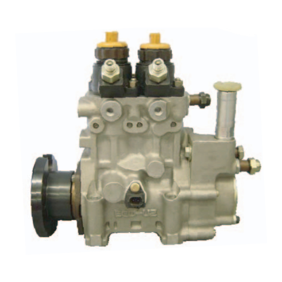
(1) HP0 Type • This system is the first common rail system that DENSO commercialized. It uses an HP0 type supply pump and is mounted in large trucks and large buses. Exterior View of Main System Components... - Page 13 Operation Section – (2) HP2 Type • This system uses a type of HP2 supply pump that has been made lighter and more compact, and is the common rail system for passenger cars and RVs instead of the ECD-V3. Exterior View of Main System Components Rail Supply Pump (HP2 Type) Injector...
- Page 14 Operation Section – Overall System Flow (Fuel) Q000926E...
- Page 15 Operation Section – (3) HP3 Type, HP4 Type HP3 Type • This system uses an HP3 type supply pump that is compact, lightweight and provides higher pressure. It is mostly mounted in passenger cars and small trucks. HP4 Type • This system is basically the same as the HP3 type, however it uses the HP4 type supply pump, which has an in- creased pumping quantity to handle larger engines.
- Page 16 Operation Section – Overall System Flow (Fuel) Various Sensors Pressure Discharge Valve Rail Pressure Limiter Rail Pressure Sensor Delivery Valve Supply Pump (HP3 or HP4) Injector : Flow of Injection Fuel Plunger (Suction : Flow of Leak Fuel Control Valve) Feed Pump Fuel Filter Fuel Tank...
-
Page 17: Supply Pump Description
Operation Section – 3. SUPPLY PUMP DESCRIPTION 3.1 HP0 Type (1) Construction and Characteristics • The HP0 supply pump is mainly made up of a pumping system as in conventional in-line pumps (two cylinders), the PCV (Pump Control Valve) for controlling the fuel discharge quantity, the cylinder recognition sensor {TDC (G) sen- sor}, and the feed pump. - Page 18 Operation Section – (2) Exploded View (Pump Control Valve) Delivery Valve Element Cylinder Recognition Sensor (TDC (G) Sensor) Tappet Roller Camshaft Priming Pump Feed Pump Q000769E...
- Page 19 Operation Section – (3) Supply Pump Component Part Functions Component Parts Functions Feed Pump Draws fuel from the fuel tank and feeds it to the pumping mechanism. Overflow Valve Regulates the pressure of the fuel in the supply pump. PCV (Pump Control Valve) Controls the quantity of fuel delivered to the rail.
- Page 20 Operation Section – PCV: Pump Control Valve • The PCV (Pump Control Valve) regulates the fuel discharge quantity from the supply pump in order to regulate the rail pressure. The fuel quantity discharged from the supply pump to the rail is determined by the timing with which the current is applied to the PCV.
- Page 21 Operation Section – CYLINDER RECOGNITION SENSOR {TDC (G) SENSOR} • The cylinder recognition sensor {TDC (G) sensor} uses the alternating current voltage generated by the change in the lines of magnetic force passing through the coil to send the output voltage to the ECU. This is the same for the engine speed sensor installed on the engine side.
- Page 22 Operation Section – (4) Supply Pump Operation Supply Pump Overall Fuel Flow • The fuel is drawn by the feed pump from the fuel tank and sent to the pumping mechanism via the PCV. The PCV adjusts the quantity of fuel pumped by the pumping mechanism to the necessary discharge quantity, and the fuel is pumped to the rail via the delivery valve.
-
Page 23: Hp2 Type
Operation Section – 3.2 HP2 Type (1) Construction and Characteristics • The supply pump is primarily composed of the two pumping mechanism (inner cam, roller, two plungers) systems, the SCV (Suction Control Valve), the fuel temperature sensor, and the feed pump (vane type), and is actuated with half the engine rotation. - Page 24 Operation Section – (2) Supply Pump Actuating Torque • Because the pumping mechanism is a tandem configuration, its peak actuating torque is one-half that of a single pump with the same discharge capacity. Single Type Tandem Type Pumping Pumping Plunger 2 Plunger 1 Feed Feed...
- Page 25 Operation Section – (3) Exploded View Regulating Valve Fuel Temperature Sensor Camshaft Inner Cam Roller Pump Body Feed Pump Shoe Delivery Valve SCV (Suction Control Valve) Check Valve Q000820E...
- Page 26 Operation Section – (4) Component Part Functions Component Parts Functions Feed Pump Draws fuel from the fuel tank and feeds it to the pumping mechanism. Regulating Valve Regulates internal fuel pressure in the supply pump. SCV (Suction Control Valve) Controls the quantity of fuel that is fed to the plunger in order to control fuel pressure in the rail.
- Page 27 Operation Section – SCV: Suction Control Valve • A solenoid type valve has been adopted. The ECU controls the duration of the current applied to the SCV in order to control the quantity of fuel drawn into the pumping mechanism. Because only the quantity of fuel required to achieve the target rail pressure is drawn in, the actuating load of the supply pump decreases, thus improving fuel economy.
- Page 28 Operation Section – Pumping Mechanism (Plunger, Inner Cam, Roller) • The pumping mechanism is made up of the plunger, inner cam, and roller, and it draws in the fuel discharged by the feed pump and pumps it to the rail. Because the drive shaft and the inner cam have an integral construction, the ro- tation of the drive shaft directly becomes the rotation of the inner cam.
- Page 29 Operation Section – Fuel Temperature Sensor • The fuel temperature sensor is installed on the fuel intake side and utilizes the characteristics of a thermistor in which the electric resistance changes with the temperature in order to detect the fuel temperature. Thermistor Resistance - Temperature Characteristic...
- Page 30 Operation Section – (5) Supply Pump Operation Supply Pump Overall Fuel Flow • Fuel is suctioned by the feed pump from the fuel tank and sent to the SCV. At this time, the regulating valve adjusts the fuel pressure to below a certain level. Fuel sent to the feed pump has the required discharge quantity adjusted by the SCV and enters the pumping mechanism through the check valve.
- Page 31 Operation Section – Fuel Discharge Quantity Control • The diagram below shows that the suction starting timing (SCV (Suction Control Valve) ON) is constant (determined by the pump speed) due to the crankshaft position sensor signal. For this reason, the fuel suction quantity is controlled by changing the suction ending timing (SCV OFF).
-
Page 32: Hp3 Type
Operation Section – 3.3 HP3 Type (1) Construction and Characteristics • The supply pump is primarily composed of the pump unit (eccentric cam, ring cam, two plungers), the SCV (suction control valve), the fuel temperature sensor and the feed pump (trochoid type), and is actuated at 1/1 or 1/2 the engine rotation. - Page 33 Operation Section – (2) Exploded View Delivery Valve Element Sub-Assembly Delivery Valve Fuel Temperature Sensor Plunger Feed Pump Regulating Valve (Suction Control Valve) Ring Cam Pump Housing Plunger Eccentric Cam Camshaft Delivery Valve Element Sub-Assembly Q000836E...
- Page 34 Operation Section – (3) Component Part Functions Component Parts Functions Feed Pump Draws fuel from the fuel tank and feeds it to the plunger. Regulating Valve Regulates the pressure of the fuel in the supply pump. SCV (Suction Control Valve) Controls the quantity of fuel that is fed to the plungers.
- Page 35 Operation Section – Suction Control Valve (SCV) • In contrast to the HP2, the SCV for the HP3 supply pump is equipped with a linear solenoid valve. The fuel flow vol- ume supplied to the high-pressure plunger is controlled by adjusting the engine ECU supplies power to the SCV (duty ratio control).
- Page 36 Operation Section – Duty Ratio Control - The engine ECU outputs sawtooth wave signals with a constant frequency. The value of the current is the effective (average) value of these signals. As the effective value increases, the valve opening decreases, and as the effec- tive value decreases, the valve opening increases.
- Page 37 Operation Section – Compact SCV Feed Pump Large Needle Valve Opening Q002321E When the SCV Energized Duration (Duty ON Time) is Long - When the energization time is long, the average current flowing to the solenoid is large. As a result, the needle valve is pressed out (in the compact SCV, the needle valve is pulled), creating a small valve opening.
- Page 38 Operation Section – Compact SCV Feed Pump Small Valve Needle Valve Opening Q002322E...
- Page 39 Operation Section – Normally Closed Type - When the solenoid is energized, the needle valve is pressed upon (in the compact SCV, the cylinder is pulled upon) by the armature, completely opening the fuel passage and supplying fuel to the plunger. (Total quantity suctioned →...
- Page 40 Operation Section – When the SCV Energized Duration (Duty ON Time) is Long - When the energization time is long, the average current flowing to the solenoid is large. As a result, the needle valve is pushed out (in the compact SCV, the needle valve is pulled), creating a large valve opening. Subsequently, the fuel suction quantity increases.
- Page 41 Operation Section – When the SCV Energized Duration (Duty ON Time) is Short - When the energization time is short, the average current flowing through the solenoid is small. As a result, the nee- dle valve is returned to the original position by spring force, creating a small valve opening. Subsequently, the fuel suction quantity decreases.
- Page 42 Operation Section – Pump Unit (Eccentric Cam, Ring Cam, Plunger) • The eccentric cam is attached to the camshaft and the ring cam is installed on the eccentric cam. There are two plung- ers at positions symmetrical above and below the ring cam. Plunger A Ring Cam Camshaft...
- Page 43 Operation Section – Delivery Valve • The delivery valve for the HP3 has an integrated element and is made up of the check ball, spring, and holder. When the pressure at the plunger exceeds the pressure in the rail, the check ball opens to discharge the fuel. Check Ball Element Holder...
- Page 44 Operation Section – (4) Supply Pump Operation Supply Pump Overall Fuel Flow • The fuel is suctioned by the feed pump from the fuel tank and sent to the SCV. At this time, the regulating valve adjusts the fuel pressure to below a certain level. The fuel sent from the feed pump has the required discharge quantity ad- justed by the SCV, and enters the pump unit through the suction valve.
- Page 45 Operation Section – Operation • The discharge quantity is controlled by SCV control, the same as for the HP2, however it differs from the HP2 in that the valve opening is adjusted by duty ratio control. • In the intake stroke, the spring makes the plunger follow the movement of the ring cam, so the plunger descends to- gether with the ring cam.
-
Page 46: Hp4 Type
Operation Section – 3.4 HP4 Type (1) Construction and Characteristics • The HP4 basic supply pump construction is the same as for the HP3. The composition is also the same as the HP3, being made up of the pump unit (eccentric cam, ring cam, plunger), the SCV (suction control valve), the fuel temper- ature sensor, and the feed pump. - Page 47 Operation Section – (2) Exploded View Filter Fuel Temperature Sensor Feed Pump Regulating Valve Pump Body Ring Cam Camshaft Q000457E...
- Page 48 Operation Section – (3) Component Part Functions Component Parts Functions Feed Pump Draws fuel from the fuel tank and feeds it to the plunger. Regulating Valve Regulates the pressure of the fuel in the supply pump. SCV (Suction Control Valve) Controls the quantity of fuel that is fed to the plungers.
- Page 49 Operation Section – • Because the rotation of the camshaft makes the eccentric cam rotate eccentrically, the ring cam follows this and this moves the three plungers reciprocally. (The ring cam itself does not rotate.) Ring Cam Plunger #1 Plunger #2 End of Pumping Pumping Eccentric Cam...
- Page 50 Operation Section – (4) Supply Pump Operation Supply Pump Overall Fuel Flow • The fuel is suctioned by the feed pump from the fuel tank and sent to the SCV. At this time, the regulating valve adjusts the fuel pressure to below a certain level. The fuel sent from the feed pump has the required discharge quantity ad- justed by the SCV, and enters the pump unit through the suction valve.
-
Page 51: Rail Desccription
Operation Section – 4. RAIL DESCCRIPTION 4.1 Rail Functions and Composition The function of the rail is to distribute fuel pressurized by the supply pump to each cylinder injector. The shape of the rail depends on the model and the component parts vary accordingly. The component parts are the rail pressure sensor (Pc sensor), pressure limiter, and for some models a flow damper and pressure discharge valve. - Page 52 Operation Section – (1) Pressure Limiter • The pressure limiter opens to release the pressure if abnormally high pressure is generated. If pressure within the rail becomes abnormally high, the pressure limiter operates (opens). It resumes operation (closes) after the pressure falls to a certain level.
- Page 53 Operation Section – (3) Flow Damper • The flow damper reduces the pressure pulsations of the fuel in the pressurized pipe and supplies fuel to the injectors at a stabilized pressure. The flow damper also presents abnormal discharge of fuel by shutting off the fuel passage in the event of excess fuel discharge, for example due to fuel leaking from an injection pipe or injector.
- Page 54 Operation Section – (4) Pressure Discharge Valve • The pressure discharge valve controls the fuel pressure in the rail. When rail fuel pressure exceeds the target injection pressure, or when the engine ECU judges that rail fuel pressure exceeds the target value, the pressure discharge valve solenoid coil is energized.
-
Page 55: Injector Description
Operation Section – 5. INJECTOR DESCRIPTION 5.1 General Description The injector injects the pressurized fuel in the rail into the engine combustion chamber at the optimal injection timing, injection quantity, injection rate, and injection pattern, in accordance with signals from the ECU. Injection is controlled using a TWV (Two-Way Valve) and orifice. -
Page 56: Injector Construction And Features
Operation Section – 5.2 Injector Construction and Features The injector consists of a nozzle similar to the conventional "nozzle & nozzle holder", an orifice that controls the injection rate, the command piston, and a TWV (two-way solenoid valve). The basic construction is the same for the X1, X2, and G2 types. - Page 57 Operation Section – (2) X2 Type • By reducing the injector actuation load, the injector has been made more compact and energy efficient, and its injec- tion precision has been improved. The TWV directly opens and closes the outlet orifice. Control Solenoid Chamber...
- Page 58 Operation Section – (3) G2 Type • To ensure high pressure, the G2 type has improved pressure strength, sealing performance and pressure wear re- sistance. It also has improved high-speed operability, enabling higher-precision injection control and multi-injection. To Fuel Tank Connector Solenoid Valve From Rail...
-
Page 59: Injector Operation
Operation Section – 5.3 Injector Operation The injector controls injection through the fuel pressure in the control chamber. The TWV executes leak control of the fuel in the control chamber to control the fuel pressure within the control chamber. The TWV varies with the injector type. Non-Injection •... -
Page 60: Injector Actuation Circuit
Operation Section – 5.4 Injector Actuation Circuit In order to improve injector responsiveness, the actuation voltage has been changed to high voltage, speeding up both solenoid magnetization and the response of the TWV. The EDU or the charge circuit in the ECU raises the respective battery voltage to approximately 110V, which is supplied to the injector by signal from the ECU to actuate the injector. -
Page 61: Other Injector Component Parts
Operation Section – 5.5 Other Injector Component Parts (1) Hollow Screw with Damper • The hollow screw with damper enhances injection quantity accuracy, by reducing the back-pressure pulsations (pres- sure fluctuations) of the leak fuel. In addition, it minimizes the back-pressure dependence (the effect of the pressure in the leak pipe changing the injection quantity even though the injection command is the same) of the fuel in the leak pipe. - Page 62 < NOTE > QR codes are a new two-dimensional code that was developed by DENSO. In addition to injection quantity correction data, the code contains the part number and the product number, which can be read at extremely high speeds.
- Page 63 Operation Section – Handling Injectors with QR Codes (Reference) - Injectors with QR codes have the engine ECU recognize and correct the injectors, so when an injector or the engine ECU is replaced, it is necessary to register the injector's ID code in the engine ECU. Replacing the Injector - It is necessary to register the ID code of the injector that has been replaced in the engine ECU.
-
Page 64: Description Of Control System Components
Operation Section – 6. DESCRIPTION OF CONTROL SYSTEM COMPONENTS 6.1 Engine Control System Diagram (Reference) Accelerator Position Sensor Ignition Switch Signal Supply Pump Starter Signal PCV(HP0) Warm-Up Switch Signal SCV(HP2·3·4) Vehicle Speed Signal TDC(G) Sensor Fuel Temperature Engine ECU (HP0) Sensor (HP2·3·4) Charge Circuit... -
Page 65: Engine Ecu (Electronic Control Unit)
Operation Section – 6.2 Engine ECU (Electronic Control Unit) The engine ECU constantly ascertains the status of the engine through signals from the sensors, calculates fuel injec- tion quantities etc. appropriate to the conditions, actuates the actuators, and controls to keep the engine in an optimal state. -
Page 66: Various Sensors
Operation Section – (2) Operation • The high-voltage generating device in the EDU converts the battery voltage into high voltage. The ECU sends signals to terminals B through E of the EDU in accordance with the signals from the sensors. Upon receiving these signals, the EDU outputs signals to the injectors from terminals H through K. - Page 67 Operation Section – (1) Crankshaft Position Sensor (Engine Speed Sensor) and Cylinder Recognition Sensor {TDC (G) Sensor} Crankshaft Position Sensor (Engine Speed Sensor) • The crankshaft position sensor is installed near the crankshaft timing gear or the flywheel. The sensor unit is a MPU (magnetic pickup) type.
- Page 68 Operation Section – (2) Accelerator Position Sensor • The accelerator position sensor converts the accelerator opening into an electric signal and outputs it to the engine ECU. There are two types of accelerator position sensor: the hall element type and the contact type. In addition, to provide backup in the event of breakdown, there are two systems and the output voltage is offset.
- Page 69 Operation Section – (3) Intake Air Temperature Sensor • The intake air temperature sensor detects the temperature of the intake air after it has passed the turbocharger. The sensor portion that detects the temperature contains a thermistor. The thermistor, which has an electrical resistance that changes with temperature, is used to detect the intake air temperature.
- Page 70 Operation Section – (6) Fuel Temperature Sensor • This is a thermistor type sensor that detects the fuel temperature. In the HP2, HP3, and HP4 systems, this sensor is installed on the supply pump unit, but in the HP0 system, it is installed on a leak pipe from an injector. Resistance - Temperature Thermistor Characteristic...
-
Page 71: Control System
Operation Section – 7. CONTROL SYSTEM 7.1 Fuel Injection Control (1) General Description • This system effects more appropriate control of the fuel injection quantity and injection timing than the mechanical governor or timer used in the conventional injection pump. The engine ECU performs the necessary calculations based on the signals that are received from the sensors located on the engine and the vehicle. - Page 72 Operation Section – (3) Fuel Injection Quantity Control General Description • This control determines the fuel injection quantity by adding coolant temperature, fuel temperature, intake air temper- ature, and intake air pressure corrections to the basic injection quantity. The engine ECU calculates the basic injection quantity based on the engine operating conditions and driving conditions.
- Page 73 Operation Section – Set Injection Quantities • Basic Injection Quantity This quantity is determined by the engine speed and the accelerator opening. With the engine speed constant, if the accelerator opening increases, the injection quantity increases; with the accelerator opening constant, if the engine speed rises, the injection quantity decreases.
- Page 74 Operation Section – • Maximum Injection Quantity This is determined based on the basic maximum injection quantity determined by the engine speed, and the added corrections for coolant temperature, fuel temperature, intake air temperature, atmospheric temperature, intake air pressure, atmospheric pressure, and full Q adjustment resistance (only for the 1st generation HP0 system), etc. Engine Speed QB0717E Corrections...
- Page 75 Operation Section – • Atmospheric Pressure Correction The maximum injection quantity is increased and decreased according to the atmospheric pressure. When the atmo- spheric pressure is high, the maximum injection quantity is increased. Atmospheric Pressure Correction Quantity Engine Speed Q000893E •...
- Page 76 Operation Section – (4) Fuel Injection Rate Control • Although the injection rate increases with the adoption of high-pressure fuel injection, the ignition lag, which is the delay from the start of injection to the beginning of combustion, cannot be shortened to less than a certain period of time.
- Page 77 Operation Section – (5) Fuel Injection Timing Control • The fuel injection timing is controlled by the timing of the current applied to the injectors. After the main injection period is decided, the pilot injection and other injection timing is determined. Main Injection Timing - The basic injection timing is calculated from the engine speed (engine speed pulse) and the final injection quantity, to which various types of corrections are added in order to determine the optimal main injection timing.
- Page 78 Operation Section – Split Injection - The purpose of split injection is to improve the startability of a cold engine. Before the conventional main injection takes place, this function injects two or more extremely small injections of fuel. Main Injection Main Injection Pilot Injection This is the same as conventional...
- Page 79 Operation Section – (7) Other Injection Quantity Control Idle Speed Control (ISC) System • The idle speed control system controls the idle speed by regulating the injection quantity in order to match the actual speed to the target speed calculated by the computer. The ISC can be automatic ISC or manual ISC. Automatic ISC - With automatic ISC, the engine ECU sets the target speed.
- Page 80 Operation Section – Manual ISC - The idle engine speed is controlled by the setting on the idle setting button at the driver's seat. A-VCC V-IMC A-GND IMC Volume Terminal Voltage Q000901E Idle Vibration Reduction Control - This control reduces engine vibration during idle. To achieve smooth engine operation, it compares the angle speeds (times) of the cylinders and regulates injection quantity for each individual cylinder in the event of a large difference.
-
Page 81: E-Egr System (Electric-Exhaust Gas Recirculation)
Operation Section – 7.2 E-EGR System (Electric-Exhaust Gas Recirculation) (1) General Description • The E-EGR system is an electronically controlled EGR system. The EGR system recirculates a portion of the exhaust gases into the intake manifold in order to lower the combustion chamber temperature and reduce NOx emissions. However, operation of the EGR system may reduce engine power output and affect drivability. - Page 82 Operation Section – To Increase the EGR Quantity - The E-VRV duty ratio is controlled . In the stable condition shown in the bottom center diagram, an increase in the current that is applied to the coil causes the attraction force FM in the coil to increase. When this force becomes greater than the vacuum force FV that acts on the diaphragm, the moving core moves downward.
-
Page 83: Electronically Controlled Throttle (Not Made By Denso)
Operation Section – 7.3 Electronically Controlled Throttle (Not Made By DENSO) (1) General Description • The electronically controlled throttle is located upstream of the EGR valve in the intake manifold. It controls the throttle valve at an optimal angle to regulate the EGR gas and reduce noise and harmful exhaust gases. -
Page 84: Exhaust Gas Control System
Operation Section – 7.4 Exhaust Gas Control System (1) General Description • The exhaust gas control system is provided to improve warm-up and heater performance. This system actuates the exhaust gas control valve VSV, which is attached to the exhaust manifold. It increases the exhaust pressure to in- crease the exhaust temperature and engine load, in order to improve warm-up and heater performance. -
Page 85: Dpf System (Diesel Particulate Filter)
Operation Section – 7.5 DPF System (Diesel Particulate Filter) (1) General Description • This system reduces emissions of PM (particulate matter). In order to collect PM, a DPF cleaner with built-in catalytic filter is mounted on the center pipe. The collected PM is handled with combustion processing during operation. (2) System Configuration Rail Intake Air... - Page 86 Operation Section – Differential Pressure Sensor • The differential pressure sensor detects the difference in pressure at the front and rear of the DPF, and outputs a sig- nal to the engine ECU. The sensor portion is a semiconductor type pressure sensor that utilizes the piezoelectric ef- fect through a silicon element, and amplifies and outputs the voltage with its IC circuit.
-
Page 87: Dpnr System (Diesel Particulate Nox Reduction)
Operation Section – 7.6 DPNR SYSTEM (DIESEL PARTICULATE NOx REDUCTION) (1) General Description • This system reduces the emissions of PM (particulate matter) and NOx. The DPNR catalyst mounted in the center pipe collects and regenerates PM and reduces NOx all at the same time. The collected PM is handled with combus- tion processing during operation. -
Page 88: Diagnosis
Operation Section – 8. DIAGNOSIS 8.1 Outline Of The Diagnostic Function The diagnostic function enables a system to self-diagnose its own malfunctions. If abnormal conditions occur in the sen- sors or actuators used in the control systems, the respective systems convert the malfunction signals into codes and transmit them to the engine ECU. -
Page 89: Diagnosis Inspection Using The Mil (Malfunction Indicator Light)
Operation Section – 3) Checking the Freeze Frame Data: If the symptom that out- puts a DTC cannot be duplicated, check the freeze frame data. 4) Erasing DTCs from memory: Operate in accordance with the instructions shown on the screen to display the "DTC DTC (ECD Erasure) check"... - Page 90 Operation Section – Reading DTCs 1 • Turn the ignition switch ON and count the number of times the MIL (Malfunction Indicator Light) blinks · Normal Operation 0.26sec 0.26sec Repeat Malfunction Indicator Light 0.26sec Jump Terminals TE1 and TC · Malfunction (Codes "12"...
-
Page 91: Throttle Body Function Inspection
Operation Section – 8.4 Throttle Body Function Inspection < CAUTION > • Be sure to inspect the function of the throttle body after it has been disassembled and reassembled, or after any of its components have been removed and reinstalled. •... -
Page 92: End Of Volume Materials
Two types of common rail fuel injection systems are in use today. One is the common rail system that pressurizes the fuel and injects it directly into the cylinders. DENSO was the first in the world to introduce a commercial application of this system. -
Page 93: Higher Injection Pressure, Optimized Injection Rates, Higher Injection Timing Control Precision, Higher Injection Quantity Control Precision
Operation Section – 9.3 Higher Injection Pressure, Optimized Injection Rates, Higher Injection Timing Control Precision, Higher Injection Quantity Control Precision (1) Higher Injection Pressure • The fuel that is injected from the nozzle turns into finer particles as the fuel injection pressure increases. This improves combustion and reduces the amount of smoke contained in the exhaust gases. - Page 94 Operation Section – • As the injection pressure increases, the injection rate increases accordingly. The increase in injection rate leads to an increase in the volume of the air-fuel mixture that is created between the start of injection until ignition (the ignition lag period).
-
Page 95: Image Of Combustion Chamber Interior
Operation Section – 9.4 Image Of Combustion Chamber Interior With conventional injection methods, because an excessive quantity of fuel was injected in the initial period, the explo- sion pressure rose excessively, leading to the generation of noise such as engine knocking sounds. To improve this condition through pilot injection, initially only the necessary and adequate quantity of fuel is injected. -
Page 96: Repair Section
Repair Section – 1. DIESEL ENGINE MALFUNCTIONS AND DIAGNOSTIC METH- ODS (BASIC KNOWLEDGE) 1.1 Combustion State and Malfunction Cause Depending on the state of combustion in a diesel engine, diesel knock as well as the color of the exhaust gas may change. -
Page 97: Troubleshooting
Repair Section – (2) White Smoke White smoke: Uncombusted fuel that has been vaporized and then discharged. • White smoke is generated when combustion occurs at a relatively low temperature, resulting in the exhaust of un- combusted fuel and oil particles. White smoke is most likely to be generated when combustion chamber temperature is low. -
Page 98: Diagnosis Overview
Repair Section – 2. DIAGNOSIS OVERVIEW 2.1 Diagnostic Work Flow Diagnostic Procedures Receive malfunctioning vehicle Question the user to verify the nature of the malfunction. Does the malfunction reoccur? Refer to "Actions for Non-Reoccurring Malfunc- tions." Verify the malfunction symptom at the actual vehicle. -
Page 99: Inquiries
Repair Section – 2.2 Inquiries Use the Common Rail System (CRS) troubleshooting questionnaire to consult with the customer and adequately grasp the malfunction symptoms. < NOTE > Do not ask random questions. Rather, ask questions that will aid in narrowing down the possible malfunctioning system while making educated guesses based on the actual symptoms. - Page 100 Repair Section – (1) Questionnaire CRS Troubleshooting Questionnaire Vehicle Model Receiving Date Service History No / Yes ( times) Date Registered Frame No. Registration No. Occurrence Date Odometer Reading Previous Vehicles Driven: Main Area and Purpose of Use Other Customer Information...
-
Page 101: Non-Reoccurring Malfunctions
Repair Section – 2.3 Non-Reoccurring Malfunctions In cases where the malfunction does not reoccur, perform the actions below to determine the cause of the malfunction. Malfunction Symptom Idle Speed, Fully Dis- Engine Stall, Action Engine will not charged Bat- Sputtering, Start tery Poor Acceler-... - Page 102 Repair Section – Malfunction Symptom Idle Speed, Fully Dis- Engine Stall, Action Engine will not charged Bat- Sputtering, Start tery Poor Acceler- ation If it is likely that the malfunction occurs in rainy or high-tempera- Mist State ture weather, spray the vehicle with water and verify whether the malfunction occurs.
-
Page 103: Dtc Reading (For Toyota Vehicles)
Repair Section – 3. DTC READING (FOR TOYOTA VEHICLES) 3.1 DST-2 The DST-2 can check for DTCs in either normal or check mode. In comparison to the normal mode, the check mode has higher sensitivity in detecting malfunctions. Check mode is used when detection is not possible in normal mode, regardless of the assumed abnormality. -
Page 104: Troubleshooting By System
Repair Section – 4. TROUBLESHOOTING BY SYSTEM 4.1 Intake System Diagnosis Clogged air cleaner element Clogged air cleaner element Clean or replace the air cleaner. Check the suction path for leaks. Repair or replace the malfunctioning compo- • Suction path joints nent. - Page 105 Repair Section – Fuel tank interior check (modification/additions, Restore the fuel tank. position of fuel pipe inlet/outlet, clogging and holes) • Check the tank for modifications or additions. Consult with the user. - Fuel inlet/outlet position, tank piping - Foreign material inside the tank, water sep- aration - Tank-internal Zn cladding - Check the tank-internal fuel piping for the...
- Page 106 Oil level increase (engine internal leak) Check the engine. • Verify whether the oil level increases on the oil level gauge. High-pressure piping and CRS component Repair leaking high-pressure piping or replace (injector supply pump, rail) fuel leaks (engine leaking parts.
-
Page 107: Basics Of Electrical/Electronic Circuit Checks
Repair Section – (2) Fuel leak check • Connect the DST-2 to the vehicle-side test connector. • With the vehicle idling, perform the active test by following the instructions on the DST-2 display. System selection screen: TCCS a Active Test Item Name Description Control Conditions... - Page 108 Repair Section – (2) Open circuit check • When dealing with a wiring harness open circuit like that depicted in diagram 1, check continuity and/or voltage to determine the location of the open circuit. Diagram 1 Engine ECU Open Sensor Circuit Q002327E Continuity Check...
- Page 109 Repair Section – Voltage Check 1) For the circuit that applies voltage to the ECU connector ter- Diagram 4 minals, check for an open circuit by performing a voltage check. 2) As shown in diagram 4, with all connectors connected, mea- sure the voltage for the ECU 5 V output terminal between Sensor the body ground and terminal 1 of connector "A".
- Page 110 Repair Section – Ground Continuity Check 1) Remove connector "A" and connector "C", and then mea- Diagram 6 sure the resistance respectively between terminals 1 and 2 of connector "A" and ground. Engine Ω Standard Value or less < NOTE > Sensor Measure resistance while gently shaking the wiring har- ness up and down, and side-to-side.
- Page 111 Repair Section – (4) Connector connection fault verification method • Simultaneously perform the data monitor and connector voltage measurements. Ex.) Coolant temperature sensor 1. Read the "Coolant Temperature Output Voltage" value using the DST-2 data monitor. 2. Measure the voltage directly from the corresponding ECU terminal. If "1"...
-
Page 112: Troubleshooting
Repair Section – 5. TROUBLESHOOTING 5.1 Troubleshooting According to Malfunction Symptom (for TOYOTA Ve- hicles) (1) Malfunction Indicator Lamp (MIL) is lit. Description The check engine warning light is lit when the engine is running, or before the engine is started. Possible Cause The DTC is recorded in the engine ECU. - Page 113 Repair Section – Verify the output waveform of the cylinder rec- Repair or replace the cylinder recognition sen- ognition sensor. (Refer to the cylinder recogni- sor and/or the corresponding circuit. tion sensor check procedure issued by the vehicle manufacturer.) Check each injector. (Refer to the injector check Repair or replace the injector and/or the corre- procedure issued by the vehicle manufacturer.) sponding circuit.
- Page 114 Repair Section – (3) The engine stalls when idling. Description The engine stalls after starting or when idling. Possible Cause • Crankshaft position sensor • Engine ECU power supply circuit • Injector • Supply pump • Engine cooling system • Start signal circuit Clogged air cleaner element Verify that the engine is not overheated.
- Page 115 Repair Section – (4) The engine cranks normally, but does not start. Description The engine is cranked at the normal speed, but does not start. Possible Cause • Crankshaft position sensor • Engine ECU power supply circuit • Injector • Supply pump •...
- Page 116 Repair Section – (5) Idle instability following engine start Description Idle speed after starting the engine is abnormal. Possible Cause • Injector • Supply pump • Fuel filter • Engine ECU • Rail pressure sensor Clogged air cleaner element Check each injector. (Refer to the injector check Repair or replace the injector and/or the corre- procedure issued by the vehicle manufacturer.) sponding circuit.
- Page 117 Repair Section – (6) The engine returns to idle speed too slowly, or does not return at all. Description The time required for the engine to return to idle speed is longer than normal, or the engine does not return to idle speed.
- Page 118 Repair Section – (7) Rough idle Description Idle speed fluctuates, causing the engine to vibrate. Possible Cause • Engine cooling system • Crankshaft position sensor • Engine • Supply pump • Injector Clogged air cleaner element Check parts that may be a source of abnormal Repair the engine.
- Page 119 Repair Section – (8) The engine stalls when decelerating. Description The engine suddenly stops when decelerating. Possible Cause • Engine cooling system • Crankshaft position sensor • Engine ECU power supply circuit • Supply pump • Injector • Start signal circuit Clogged air cleaner element Verify that the engine is not overheated.
- Page 120 Repair Section – (9) Poor engine output, poor acceleration Description Deficient engine performance. Possible Cause • EGR system • Injector • Mass Air Flow (MAF) meter • Crankshaft position sensor • Accelerator position sensor • Boost pressure sensor • Supply pump •...
- Page 121 Repair Section – Check the Exhaust Gas Recirculation (EGR) Repair or replace the EGR system. system. (Refer to the EGR system check proce- dure issued by the vehicle manufacturer.) Perform the accelerator pedal position sensor Repair or replace the accelerator position sen- function check.
- Page 122 Repair Section – (10) Knocking, abnormal noise Description Abnormal combustion occurs, and a knocking sound is generated. Possible Cause • Engine • Injector • Glow control system • Crankshaft position sensor Clogged air cleaner element Repair the glow control system. (Refer to the Repair the glow control system.
- Page 123 Repair Section – (11) Poor fuel economy Description More fuel than normal is being consumed. Possible Cause • Engine • Injector • Supply pump Clogged air cleaner element Check each injector. (Refer to the injector check Repair or replace the injector and/or the corre- procedure issued by the vehicle manufacturer.) sponding circuit.
- Page 124 t i o – (12) Black Smoke Description Black smoke is being exhausted. Possible Cause • Injector • Supply pump • EGR system • Engine ECU • Electronic control throttle • Rail pressure sensor • Mass Air Flow (MAF) meter •...
- Page 125 Repair Section – Check each injector. (Refer to the injector check Repair or replace the injector and/or the corre- procedure issued by the vehicle manufacturer.) sponding circuit. Check the engine ECU power supply. (Refer to Repair the engine ECU power supply. the engine ECU power supply circuit diagram issued by the vehicle manufacturer.) Check the supply pump and the supply pump...
- Page 126 Repair Section – (13) White smoke Description White smoke is being exhausted. Possible Cause • Fuel filter • Injector • Supply pump • EGR system • Engine ECU • Electronic control throttle • Rail pressure sensor Clogged air cleaner element Check the fuel filter.
-
Page 127: Other Malfunction Symptoms
Malfunctions caused by components other than the CRS There are occasions when a malfunction that appears to be generated by the CRS is actually caused by a different com- ponent or system. For instance, engine mechanical parts and the fuel system may cause malfunction symptoms iden- tical to symptoms generated by the CRS. - Page 128 Repair Section – Malfunction Faulty Item Cause Action Symptom Poor valve clearance Adjust the valve clearance or replace the bearing. Poor valve seat contact Break in, or replace the valve and valve seat. Faulty idling Engine Low coolant temperature Perform warm-up operation. Large difference in cylinder-to-cylinder Overhaul the engine.
-
Page 129: Diagnosis Codes (Dtc)
P2###: Determined by manufacturer P3###: Mixture of items determined by SAE/ISO and items determined by the vehicle manufacturer. DTC Chart (example for HINO and TOYOTA vehicles) DTC codes that apply to the CRS are listed below (compatible with the DST-2.) DTC Description P0006 Fuel shutoff valve "A"... - Page 130 Repair Section – DTC Description P0118 Coolant temperature sensor circuit high voltage P0119 Coolant temperature sensor circuit intermittent operation P0120 Accelerator position sensor, switch "A" circuit related P0121 Accelerator position sensor switch "A" circuit range/performance P0122 Accelerator position sensor switch "A" circuit low voltage P0123 Accelerator position sensor switch "A"...
- Page 131 Repair Section – DTC Description P0275 Cylinder correction quantity error- #5 cylinder P0278 Cylinder correction quantity error- #6 cylinder P0299 Turbo/supercharger supercharge deficiency P0335 Crankshaft position sensor, "A" circuit related P0339 Crankshaft position sensor "A" circuit intermittent operation P0340 Cylinder recognition sensor, "A" circuit related P0400 EGR flow volume abnormality P0404...
- Page 132 Repair Section – DTC Description P2122 Accelerator position sensor, switch "D" circuit low input P2123 Accelerator position sensor, switch "D" circuit high input P2125 Accelerator position sensor, switch "E" circuit related P2127 Accelerator position sensor, switch "E" circuit low input P2128 Accelerator position sensor, switch "E"...
- Page 133 Repair Section –...
- Page 134 Published : August 2004 Second Issu: September 2007 Edited and published by: DENSO CORPORATION Service Department 1-1 Showa-cho, Kariya, Aichi Prefecture, Japan...
Need help?
Do you have a question about the CRS and is the answer not in the manual?
Questions and answers