Table of Contents
Advertisement
Quick Links
Advertisement
Table of Contents

Summary of Contents for Torc REMOTETASK ALPHA
- Page 2 ™ EMOTE LPHA Parts and Installation Manual V1.1...
-
Page 3: General Information
Copyright © 2018 TORC Robotics, Inc. All Rights Reserved. All information contained in this manual is believed to be accurate at the time of printing; however, TORC Robotics, Inc. reserves the right to make modifications to the specifications and operation of this product without obligation to notify any person or entity of such revision. -
Page 4: Foreword
™ A EMOTE LPHA ARTS AND NSTALLATION ANUAL 1.2 Foreword This manual provides safety information and installation instructions for the RemoteTask Remote Control System for CAT Alpha series SSL and CTL machines. Some photographs or illustrations in this publication show details or attachments that can be different from your machine. -
Page 5: Table Of Contents
™ A EMOTE LPHA ARTS AND NSTALLATION ANUAL 1.4 Table of Contents ENERAL NFORMATION Assignment of Liability Foreword Compatible Machines Table of Contents AFETY NFORMATION General Safety Information Safety Messages EMOTE LPHA ARTS AND OOLS RTA01 RemoteTask Parts List Machine Interface Assembly Parts Overview Required Tools Required Materials Required CAT Parts and Hardware... - Page 6 ™ A EMOTE LPHA ARTS AND NSTALLATION ANUAL 5.7.1 General Information 5.7.2 Installation Instructions NSTALLATION Attaching the Remote Enabled Machine Label Post Installation Testing 6.2.1 Test In-Cab Machine Controls 6.2.2 Test Remote Operation of the Machine 6.2.3 Test the Emergency Stop Function 6.2.4 Test Remote Controls NSTALLING...
-
Page 7: Safety Information
The list of procedures and hazards identified by WARNING and NOTICE labels is not all inclusive. TORC® cannot anticipate every possible circumstance that might involve a potential hazard. The warnings in this publication and on the product are, therefore, not all inclusive. -
Page 8: Safety Messages
Be sure to also review the safety messages in the CAT Operation and Maintenance Manual. TORC® cannot anticipate every possible circumstance that might involve a potential hazard; therefore, the warnings in this publication and on the product are not all inclusive. The operator must be alert to potential hazards and ensure that any operating technique used is safe. - Page 9 ™ A EMOTE LPHA ARTS AND NSTALLATION ANUAL Do not approach the machine if the Active Indicator (amber beacon) is flashing. Verify with the operator that it is safe to approach the machine. Do Not Operate With Suspected Failures. If you suspect there is damage to the RemoteTask, contact a CAT dealer to have it inspected before further use.
-
Page 10: Remotetask Alpha Parts And Tools
™ A EMOTE LPHA ARTS AND NSTALLATION ANUAL 3 RemoteTask Alpha Parts and Tools 3.1 RTA01 RemoteTask Parts List Parts included in the RTA01-MI RemoteTask Machine Interface Assembly Quantity Part Number Description RTA01-MI-MIM Machine Interface Module, Mounting Bracket and Hardware... -
Page 11: Machine Interface Assembly Parts Overview
™ A EMOTE LPHA ARTS AND NSTALLATION ANUAL 3.2 Machine Interface Assembly Parts Overview Machine Interface Module (MIM) RTA01-MI-MIM The Machine Interface Module is comprised of the on-machine RemoteTask ECM and mounting plate. This device wirelessly communicates with the RemoteTask controller. The part number and serial number remain visible after installation;... - Page 12 ™ A EMOTE LPHA ARTS AND NSTALLATION ANUAL Remote Enable Interface (REI) RTA01-MI-REI The Remote Enable Interface is mounted on the engine cover on the rear of the machine. It provides the necessary controls and indicators for the RemoteTask system, including an Emergency Stop button, LED indicators, and a key switch to enter/exit remote-control and pairing modes.
-
Page 13: Required Tools
™ A EMOTE LPHA ARTS AND NSTALLATION ANUAL 3.3 Required Tools Description Quantity 10mm Socket 13mm Socket 16mm Socket 18mm Wrench 24mm Wrench 4mm Hex Driver 3mm Drill Bit 5mm Drill Bit 6.5mm Drill Bit 6” Extension Bar 9” Extension Bar Allen Wrench Deburring Tool Drill... -
Page 14: Required Cat Parts And Hardware
™ A EMOTE LPHA ARTS AND NSTALLATION ANUAL 3.5 Required CAT Parts and Hardware The Machine Interface Module (MIM) is designed to be mounted to the machine air conditioner plate. If the machine is not equipped with an air conditioner, additional Caterpillar parts must be purchased to supply the mounting surface for the MIM. -
Page 15: Pre-Installation
™ A EMOTE LPHA ARTS AND NSTALLATION ANUAL 4 Pre-Installation All Caterpillar safety and service procedures and precautions should be followed during product installation or servicing. In the event of a conflict of direction, Caterpillar procedures override any procedures found in this manual. Ensure machine is a safe state for installation or servicing. -
Page 16: Installing The Machine Interface Assembly
™ A EMOTE LPHA ARTS AND NSTALLATION ANUAL 5 Installing the Machine Interface Assembly 5.1 Installing the Machine ECM Interface (MEI) 5.1.1 General Information The MEI (TPN:10572) is installed to the ECM connector closest to the bottom of the cab. Required Tools and Materials Tools Quantity... -
Page 17: Installation Instructions
™ A EMOTE LPHA ARTS AND NSTALLATION ANUAL 5.1.2 Installation Instructions 1. REMOVE UNDER-CAB ECM CONNECTOR A. Locate the two center ECM connectors on the rear of the cab. The MEI will will be added to the ECM connector closest to the bottom of the cab. - Page 18 ™ A EMOTE LPHA ARTS AND NSTALLATION ANUAL E. Remove the connector cover. F. Pull the connector downward to unplug it from the machine. 2. INSTALLING THE MEI A. Locate cavity plugs 40 and 48 in the housing. ECM I ACHINE NTERFACE NSTALLATION...
- Page 19 ™ A EMOTE LPHA ARTS AND NSTALLATION ANUAL B. Using needle nose pliers, remove the cavity plugs from positions 40 and 48. Discard the cavity plugs. C. Insert a flathead screwdriver between the terminal retainer and gently pry to unlock. There are 2 clips which need to be released.
- Page 20 ™ A EMOTE LPHA ARTS AND NSTALLATION ANUAL E. Insert the green MEI wire into pin F. Insert the yellow MEI wire into pin G. Press wires firmly until they lock into the connector. An audible click will indicate that the wire is secured H.
- Page 21 ™ A EMOTE LPHA ARTS AND NSTALLATION ANUAL 3. REINSTALLING THE CONNECTOR A. Insert two zip ties into the holes in the connector cover. B. Verify the MEI runs parallell with the other wires connected to the retainer. Reattach the cover to the connector.
- Page 22 ™ A EMOTE LPHA ARTS AND NSTALLATION ANUAL D. Plug the connector back in. E. Use the 4mm hex driver to secure the connector. ECM I ACHINE NTERFACE NSTALLATION ERSION...
-
Page 23: Installing The Machine Interface Module (Mim)
™ A EMOTE LPHA ARTS AND NSTALLATION ANUAL 5.2 Installing the Machine Interface Module (MIM) 5.2.1 General Information The Machine Interface Module (RTA01-MI- MIM) is installed on the CAT Air Conditioning plate underneath the cab area The plate which mounts the HVAC duct must be installed in order to complete RemoteTask MIM installation. -
Page 24: Machine Requirements
™ A EMOTE LPHA ARTS AND NSTALLATION ANUAL 5.2.2 Machine Requirements The Machine Interface Module (MIM) is designed to be mounted to the machine air conditioner plate. If the machine is not equipped with an air conditioner, additional Caterpillar parts must be purchased to supply the mounting surface for the MIM. -
Page 25: Installation Instructions
™ A EMOTE LPHA ARTS AND NSTALLATION ANUAL 5.2.3 Installation Instructions 1. MODIFYING THE CAT AC PLATE A. At the back of this manual, locate and remove the MIM Install Locating Template (D05142). B. Use scissors to cut template along indicated lines (see template). - Page 26 ™ A EMOTE LPHA ARTS AND NSTALLATION ANUAL E. Apply cutting oil to the marked areas. F. Use 5mm drill bit to drill the 4 holes. G. Deburr all holes. H. Apply cutting oil to the holes and use an M6x1.0 tap to thread all holes.
- Page 27 ™ A EMOTE LPHA ARTS AND NSTALLATION ANUAL 2. INSTALLING THE MIM A. Align the 4 holes on the MIM mounting plate with the 4 holes previously drilled in the panel. B. Ensure the MIM is oriented as shown with the connectors pointing to the near end of the plate.
- Page 28 ™ A EMOTE LPHA ARTS AND NSTALLATION ANUAL F. Tighten screws to 10.5Nm (7.7 ft- lbs). 3. INSTALLING THE MODIFIED AIR CONDITIONING PLATE A. Locate required CAT hardware listed in section 5.2.2 B. Lower the cab. Reference the applicable Cat Operation and Maintenance manual for detailed instructions on lowering the cab.
- Page 29 ™ A EMOTE LPHA ARTS AND NSTALLATION ANUAL F. Install washer (8T-4821) on the M12 bolt and place the bolt in the opening, with the head of the bolt inside the cab. G. Lift the cab and secure. NOTE: Ensure the bolt and washer stay in place as the cab is being lifted.
- Page 30 ™ A EMOTE LPHA ARTS AND NSTALLATION ANUAL Locate the modified air conditioning plate. J. Orient the plate openings over the holes and mount the left side of the plate onto the previously installed bolt as shown. K. Install washer (9X-2038) onto an M6 screw and install into the air conditioner plate mounting hole.
- Page 31 ™ A EMOTE LPHA ARTS AND NSTALLATION ANUAL M. Install washer (9X-2038) and M12 nut onto the bolt previously installed in the cab. ACHINE NTERFACE MODULE NSTALLATION ERSION...
- Page 32 ™ A EMOTE LPHA ARTS AND NSTALLATION ANUAL N. Feed T50 TORX Driver and extension through the side of the cab to tighten the bolt. O. Use T50 TORX Driver and 18mm wrench to tighten bolt and secure it in place P.
-
Page 33: Installing The Remote Enable Interface (Rei)
™ A EMOTE LPHA ARTS AND NSTALLATION ANUAL 5.3 Installing the Remote Enable Interface (REI) 5.3.1 General Information The REI is mounted on (RTA01-MI-REI) the engine cover on the rear of the machine. Required Tools and Materials Tools Quantity Utility Knife Scissors Spring Punch Drill... -
Page 34: Installation Instructions
™ A EMOTE LPHA ARTS AND NSTALLATION ANUAL 5.3.2 Installation Instructions 1. MODIFYING THE ENGINE ACCESS COVER A. Locate the mounting area for the REI, on the stationary portion of the right rear engine cover. B. At the back of this manual, locate and remove the REI Install Locating Template (D05143). - Page 35 ™ A EMOTE LPHA ARTS AND NSTALLATION ANUAL E. Apply cutting oil to drill areas. F. Drill 6.5mm holes at each of the 4 marked positions, starting with 3mm pilot holes. G. Deburr the holes as necessary. NOTE: Place shop towels under the engine cover to contain cutting oil and drill debris.
- Page 36 ™ A EMOTE LPHA ARTS AND NSTALLATION ANUAL C. Feed the screw through the bottom of the engine cover into the previously drilled hole as shown. D. Use 10mm socket to install all screws securing the REI to the machine. E.
-
Page 37: Installing The Power Relay Module (Prm)
™ A EMOTE LPHA ARTS AND NSTALLATION ANUAL 5.4 Installing the Power Relay Module (PRM) 5.4.1 General Information The PRM (RTA01-MI-PRM) is installed on the back of the cab, on the right side. Required Tools and Materials Tools Quantity T25 TORX Driver 5.4.2 Installation Instructions 1. - Page 38 ™ A EMOTE LPHA ARTS AND NSTALLATION ANUAL B. Locate the 3 indicated OEM screws. C. Use the T25 TORX driver to loosen the screws, allowing enough room to slide the PRM bracket onto the screws. NOTE: Do not over tighten screws. These screws are threaded into plastic which will easily strip out.
-
Page 39: Installing The Machine Interface Harness (Mih)
™ A EMOTE LPHA ARTS AND NSTALLATION ANUAL 5.5 Installing the Machine Interface Harness (MIH) 5.5.1 General Information The MIH (TPN: 10115) routes from the chassis firewall to the center rear of the cab. Required Tools and Materials Tools Quantity Flush Cut Pliers Materials Description... -
Page 40: Installation Instructions
™ A EMOTE LPHA ARTS AND NSTALLATION ANUAL 5.5.2 Installation Instructions 1. INTERFACING WITH MACHINE CONNECTORS A. Locate the indicated OEM Deutsch circular connector closest to the chassis body. B. Disconnect the OEM connector. C. Route the Machine Interface Harness (MIH) connectors C502, C503, C506 and C507 along existing harnesses toward the disconnected connector. - Page 41 ™ A EMOTE LPHA ARTS AND NSTALLATION ANUAL E. Connect the circular MIH connector C502 to the previously disconnected OEM plug. F. Locate the indicated 14-position Delphi connectors on the right side of the machine. G. Unlock the red retainer on the connectors and disconnect.
- Page 42 ™ A EMOTE LPHA ARTS AND NSTALLATION ANUAL J. Connect MIH connector C506 to the male OEM Delphi connector. K. Reengage the red retainer on the connectors. L. Ensure harness is neatly routed and wires are not pinched or strained. M.
- Page 43 ™ A EMOTE LPHA ARTS AND NSTALLATION ANUAL 2. INSTALLING CAB CONNECTORS A. Route the unconnected sections of the MIH along the existing harness toward the back of the cab as shown. B. Use zip ties to loosely secure. C. Route MIH connector C501 to the branch in the harness at the top-rear of the cab.
- Page 44 ™ A EMOTE LPHA ARTS AND NSTALLATION ANUAL F. Locate the existing OEM Deutsch connector attached to the harness. NOTE: If product link is installed, this connector will be connected to the product link module. G. Remove existing OEM Deutsch connector from the cover or CAT Product Link module.
- Page 45 ™ A EMOTE LPHA ARTS AND NSTALLATION ANUAL J. Install the existing OEM Deutsch connector into female MIH connector C508. C508 K. Secure connectors to existing harness with zip ties. L. Locate the uncovered Machine ECM Interface (MEI) connector (P/N 8694) previously installed in section 5.1.
- Page 46 ™ A EMOTE LPHA ARTS AND NSTALLATION ANUAL M. Plug the MEI connector into the MIH connector C511. N. Use zip ties to secure connectors to the existing harness. C511 O. Locate the existing OEM 2-position Delphi connector to the left of the power relays.
- Page 47 ™ A EMOTE LPHA ARTS AND NSTALLATION ANUAL R. Remove the 15 amp fuse from the existing connector. NOTE: Save the 15 amp fuse and OEM connector cover for installation into the Under Cab Harness in section 5.6. S. Locate Machine Interface Harness (MIH) connector C510.
- Page 48 ™ A EMOTE LPHA ARTS AND NSTALLATION ANUAL 3. SECURING THE HARNESS A. Ensure the Machine Interface Harness connectors are routed neatly and no wires are strained or pinched. B. Tighten all zip ties. C. Cut all zip tie ends. ACHINE NTERFACE ARNESS...
-
Page 49: Installing The Under Cab Harness (Uch)
™ A EMOTE LPHA ARTS AND NSTALLATION ANUAL 5.6 Installing the Under Cab Harness (UCH) 5.6.1 General Information The UCH (TPN: 10114) routes from the MIM in the front of the cab to the top rear of the cab. Required Tools and Materials Description Quantity Ratchet... -
Page 50: Installation Instructions
™ A EMOTE LPHA ARTS AND NSTALLATION ANUAL 5.6.2 Installation Instructions 1. CONNECTING THE UNDER CAB HARNESS TO THE MIM A. Locate Under Cab Harness connectors C104 and C101. B. Route both connectors along the OEM harness and secure loosely with zip ties at the base of the cab C104 as shown. - Page 51 ™ A EMOTE LPHA ARTS AND NSTALLATION ANUAL View from under the cab E. Route connectors to the bottom right side of the cab toward the MIM as shown. F. Install connector C115 into MIM connector C NDER ARNESS NSTALLATION ERSION...
- Page 52 ™ A EMOTE LPHA ARTS AND NSTALLATION ANUAL G. Install connector C114 into connector C. H. Install connector C116 into connector D. NOTE: MIM connector B is not used and arrives with a preinstalled plug. Ensure open plugs are always sealed to protect from dust and moisture.
- Page 53 ™ A EMOTE LPHA ARTS AND NSTALLATION ANUAL E. Route MIH connector C501 behind OEM cab harness. F. Connect the MIH connector C501 C501 with the UCH circular connector C101. C101 G. Tuck the mated circular connectors behind the OEM harness. H.
- Page 54 ™ A EMOTE LPHA ARTS AND NSTALLATION ANUAL K. Locate Under Cab Harness connector C104 (ring terminal). C104 L. Route C104 along the back of the cab, behind the OEM harness. M. Use the 16mm wrench and existing nut to secure C104 on the ground point.
- Page 55 ™ A EMOTE LPHA ARTS AND NSTALLATION ANUAL 3. CONNECTING UCH TO THE FUSE DISTRIBUTION MODULE A. Locate UCH connector C107 (ring terminal). B. Ensure C107 is routed near the previously installed Power Relay Module. C104 C. Remove the boot covering the outside bolt on the Power Relay Module.
- Page 56 ™ A EMOTE LPHA ARTS AND NSTALLATION ANUAL H. Locate Under Cab Harness connectors C108, C109, and C112 (red booted ring terminals). Locate the 4 studs on the front of the Fuse Distribution Module. J. Use the 10mm socket to unscrew the nuts from the 3 inside studs.
- Page 57 ™ A EMOTE LPHA ARTS AND NSTALLATION ANUAL View from under the cab N. Secure the provided boots over the studs. O. Locate UCH connectors C110 and C113. C110 C113 NDER ARNESS NSTALLATION ERSION...
- Page 58 ™ A EMOTE LPHA ARTS AND NSTALLATION ANUAL P. Insert connector C110 into the inside connector on the Power Relay Module C110 Q. Insert connector C113 into the outside connector on the Power Relay Module. C113 4. CONNECTING CAT FUSE A.
- Page 59 ™ A EMOTE LPHA ARTS AND NSTALLATION ANUAL B. Locate 15 amp fuse and connector cover previously removed from the CAT connector in section 5.5. C. Insert the 15 amp fuse into C106 D. Attach CAT connector cover to C106 E.
- Page 60 ™ A EMOTE LPHA ARTS AND NSTALLATION ANUAL 5. CONNECTING C105 A. Locate Under Cab Harness connector C105 (ring terminal). C105 B. Route C105 toward the OEM power bus bar. C. Remove the boot covering the outside stud. View from under the cab NDER ARNESS NSTALLATION...
- Page 61 ™ A EMOTE LPHA ARTS AND NSTALLATION ANUAL D. Use 13mm socket to remove existing nut and washer from the outside stud E. Use the existing nuts to secure connector C105 to the stud. View from under the cab F. Replace boot over the stud. NDER ARNESS NSTALLATION...
- Page 62 ™ A EMOTE LPHA ARTS AND NSTALLATION ANUAL 6. SECURING THE HARNESS A. Locate 2 edge clip zip ties, provided with the installation kit. B. Use edge clip zip ties to secure the Under Cab Harness near MIM connectors to the AC plate and cab edge.
- Page 63 ™ A EMOTE LPHA ARTS AND NSTALLATION ANUAL C. Ensure all of the UCH connectors are routed neatly and no wires are strained or pinched. D. Tighten all zip ties. E. Clip all zip tie ends. View from under the cab NDER ARNESS NSTALLATION...
-
Page 64: Installing The User Interface Harness (Uih)
™ A EMOTE LPHA ARTS AND NSTALLATION ANUAL 5.7 Installing the User Interface Harness (UIH) 5.7.1 General Information The User Interface Harness (TPN: 10113) routes from the MIM at the bottom of the cab to the external components installed on the back and roof of the machine. - Page 65 ™ A EMOTE LPHA ARTS AND NSTALLATION ANUAL Required Tools and Materials Tools Quantity Flush cut pliers Flathead screwdriver Materials Description 8” Zip Ties As Required Do not secure wire harnesses to flexible hydraulic hoses. Hoses move during normal operation and create wear points which may damage the wiring harness.
- Page 66 ™ A EMOTE LPHA ARTS AND NSTALLATION ANUAL 5.7.2 Installation Instructions 1. INSTALLING ROOF COMPONENTS A. Locate the UIH antenna base and connectors C203 and C204. B. Locate the antenna. C. Place the antenna on the UIH base and turn it clockwise until it fits tightly on the base.
- Page 67 ™ A EMOTE LPHA ARTS AND NSTALLATION ANUAL G. Locate connectors C203 and C204 on either side of the antenna. H. Place the amber beacon (RTA01-MI- AMB) on the right side of the cab roof. Plug UIH connector C203 (black and yellow wires) into the amber beacon connector.
- Page 68 ™ A EMOTE LPHA ARTS AND NSTALLATION ANUAL 2. INSTALLING UNDER-CAB COMPONENTS A. Locate the antenna coaxial connector C 205. B. Use zip ties to loosely secure the antenna cable at the base of the existing harnesses at the chassis. C.
- Page 69 ™ A EMOTE LPHA ARTS AND NSTALLATION ANUAL F. Use zip ties to loosely secure the cable along the UCH. View from under cab NTERFACE ARNESS NSTALLATION ERSION...
- Page 70 ™ A EMOTE LPHA ARTS AND NSTALLATION ANUAL G. Route the remaining unconnected harness C201, C102, C103, and C117 behind existing harnesses in the bulkhead area. H. Route UIH connector C202 under all existing harnesses and hoses, toward the outside right of the machine NTERFACE ARNESS...
- Page 71 ™ A EMOTE LPHA ARTS AND NSTALLATION ANUAL Locate User Interface Harness connector C201 C201 J. Locate Under Cab Harness connector C102. C102 K. Connect UIH connector C201 to the UCH connector C102. NOTE: The remaining (capped) UIH connectors C103 and C117 are used for firmware upgrades and maintenance, they will remain disconnected.
- Page 72 ™ A EMOTE LPHA ARTS AND NSTALLATION ANUAL B. Route connector C202 through the opening, toward the rear of the machine. C. Ensure no wires are pinched or strained. Zip tie as necessary. D. Open the radiator access cover at the back of the machine.
- Page 73 ™ A EMOTE LPHA ARTS AND NSTALLATION ANUAL F. Test fit the connector by plugging it into the connector on the back of the REI. Position the harness along the side wall of the compartment as shown. Ensure the wires are not strained.
- Page 74 ™ A EMOTE LPHA ARTS AND NSTALLATION ANUAL H. Disconnect C202 from the REI. Route C202 out of the side opening of the radiator cover. Close the cover. J. Reconnect C202 to the REI. K. Ensure wire harness is not pinched or strained.
- Page 75 ™ A EMOTE LPHA ARTS AND NSTALLATION ANUAL C. Slowly lower the cab. Reference applicable CAT Operation and Maintenance manual for detailed instructions on lowering the cab. D. Inspect the area between the cab and the chassis to ensure no wires or components are at risk for damage.
- Page 76 ™ A EMOTE LPHA ARTS AND NSTALLATION ANUAL 6 Post Installation After the RemoteTask installation is complete, return the machine to an operational state. 1. Reconnect the Battery A. Reattach the negative battery cable at the battery. 2. Lower the Implement Arm A.
- Page 77 ™ A EMOTE LPHA ARTS AND NSTALLATION ANUAL 6.1 Attaching the Remote Enabled Machine Label The Remote Enabled Machine warning label is used to alert personnel that the machine has remote control capabilities. A magnetic label is provided with the RemoteTask system. This label should be present and legible on every machine installed with RemoteTask.
- Page 78 ™ A EMOTE LPHA ARTS AND NSTALLATION ANUAL 6.2 Post Installation Testing The purpose of this section is to validate the system after installation. This document should be used along with the RemoteTask Operation and Maintenance Manual. The Operation and Maintenance Manual provides more details about the operation, controls, and feedback provided by system.
- Page 79 ™ A EMOTE LPHA ARTS AND NSTALLATION ANUAL 6.2.2 Test Remote Operation of the Machine A. Follow the instructions in the RemoteTask Operation and Maintenance Manual section “Transition Machine from Manual to Remote Operation” and “RemoteTask Controller Startup” for initiating remote control of the machine. B.
- Page 80 ™ A EMOTE LPHA ARTS AND NSTALLATION ANUAL 7 Installing Replacement Parts 7.1 Replacing the Protection Cage Replacing the protection cage requires access to the interior of the controller unit. Perform this replacement in a clean and dry location to prevent damage to the sensitive electronics inside the unit.
- Page 81 ™ A EMOTE LPHA ARTS AND NSTALLATION ANUAL B. Lift the lid of the Remote Control Unit enclosure. C. Disconnect the white connector from the PCB connector on the lid of the Remote Control Unit enclosure. EMOTE ONTROLLER EPLACEMENT ARTS ERSION...
- Page 82 ™ A EMOTE LPHA ARTS AND NSTALLATION ANUAL D. Using a #2 Phillips screwdriver remove the (4) screws from the Remote Control Unit mounting holes. E. Remove the Remote Control Unit from the original protection cage. F. Align the Remote Control unit with the replacement protection cage as shown.
- Page 83 ™ A EMOTE LPHA ARTS AND NSTALLATION ANUAL D. Reconnect the white connector to the Remote Control Unit lid. Be careful not to touch or damage the PCB while plugging in the connector. E. Place the lid on enclosure making sure not to pinch the wiring.
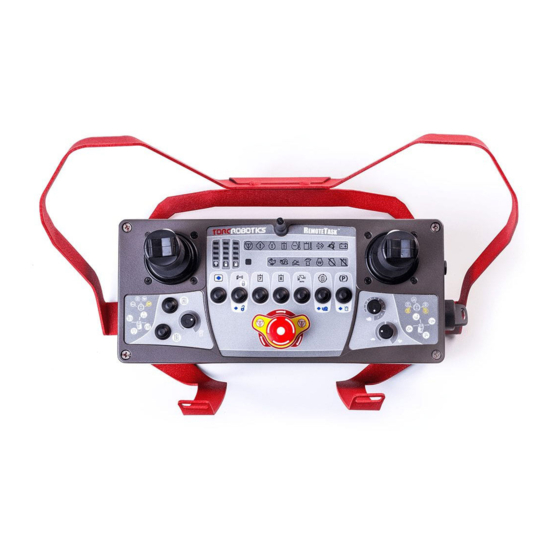
- Page 84 ™ A EMOTE LPHA ARTS AND NSTALLATION ANUAL 7.2 Installing the Operator Shoulder Harness Some of the pictures in this manual were taken with some prototype components. The appearance of these components will differ slightly from the production components. The controller lid should remain attached during installation of the operator shoulder harness.
- Page 85 ™ A EMOTE LPHA ARTS AND NSTALLATION ANUAL 2. Attaching the Shoulder Harness to the Protection Cage. A. Feed webbing straps through provided holes in the back of the protection cage. B. Fold the straps over and feed the straps through the plastic tri-bar locks.
- Page 86 ™ A EMOTE LPHA ARTS AND NSTALLATION ANUAL 7.3 Replacing the MIM Mounting Bracket This section provides instructions for replacing the MIM Mounting Bracket and Hardware (RTA01-MIM-MIMB) 1. Installing replacement MIM Mounting Bracket A. Use a T25 TORX driver to remove the 4 screws securing the MIM receiver enclosure to the bracket.
- Page 87 ™ A EMOTE LPHA ARTS AND NSTALLATION ANUAL D. Apply Loctite 242 to each of the 4 screws. E. Use a T25 TORX driver to install the 4 screws. F. Tighten screws and torque to 25 in- lbs (2.8 Nm). EMOTE ONTROLLER EPLACEMENT...
- Page 88 Such remedy shall be the sole and exclusive remedy for any breach of warranty. TORC shall not be liable for: 1. Damage to other property caused by any defects in the product, damages based upon inconvenience, loss of use of the product, loss of time, loss of profits, loss of business opportunity, loss of goodwill, interference with business relationships, or other commercial loss, even if advised of the possibility of such damages.
- Page 89 ™ A EMOTE LPHA ARTS AND NSTALLATION ANUAL 9 Templates The following pages contain the templates referenced in sections 5.2 Installing the Machine Interface Module (MIM), and 5.3 Installing the Remote Enable Interface (REI). Remove these templates from the manual and use them as directed in the above sections. EMPLATES ERSION...
- Page 90 CUT TEMPLATE ALONG DASHED LINE CUT THIS HOLE OUT TO ALIGN THIS EDGE WITH EDGE OF PLATE USE AS AN ALIGNMENT GUIDE ON THE PLATE MOUNTING BOSS CENTER PUNCH DRILL 5mm THRU ALL TAP FOR M6-1.0 SCREW 4.50 5.75 D05142-MIM INSTALL LOCATING TEMPLATE Revision A CUT TEMPLATE ALONG DASHED LINE...
- Page 91 CUT TEMPLATE ALONG DASHED LINE ALIGN THIS EDGE WITH EDGE OF PLATE 5.25 2.50 CUT TEMPLATE ALONG DASHED LINE CENTER PUNCH 6.5mm THRU ALL D05143-REI INSTALL LOCATING TEMPLATE Revision A CUT TEMPLATE ALONG DASHED LINE...
Need help?
Do you have a question about the REMOTETASK ALPHA and is the answer not in the manual?
Questions and answers