Table of Contents
Advertisement
Marine Products
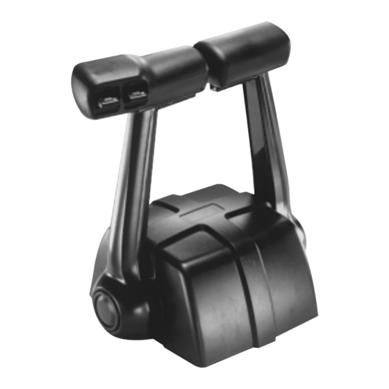
SL-3 Engine Controls
Owner's Manual
This manual must be accessible to the owner/user of this Morse
marine product.
Includes installation, operation and maintenance instructions
for your Morse marine product.
Please read these Instructions through carefully and entirely
before beginning Installation.
All specifi cations and features are subject to change without notice.
®2006 Telefl ex Marine - 212442 (Rev 1)
Advertisement
Table of Contents

Summary of Contents for morse SL-3
- Page 1 Marine Products SL-3 Engine Controls Owner’s Manual This manual must be accessible to the owner/user of this Morse marine product. Includes installation, operation and maintenance instructions for your Morse marine product. Please read these Instructions through carefully and entirely before beginning Installation.
-
Page 2: Operational Features
OPERATIONAL FEATURES PUSH BUTTON FOR NEUTRAL THROTTLE OPERATION ADJUSTABLE THROTTLE FRICTION PUSH BUTTON: Used for starting or engine warm-up. When the hand lever is in the neutral detent position, depress the button in the center of the handle to enable operation of the throttle without engaging forward or reverse gear. -
Page 3: Standard Control Features
INTRODUCTION The Morse ® Model SL-3 Control provides both shift and throttle operation for outboards, inboard/outboards, or inboards with hydraulic* transmissions, or small manual transmissions (Hurth ® , Yanmar ® ) with light shifting loads of 15 lbs (6.8 kg) max. It can be ®... -
Page 4: Tools Needed For Installation
TOOLS NEEDED FOR INSTALLATION OTHER EQUIPMENT NEEDED: 1. Two (2) each Telefl ex 3300/33C type cables, or two (2) each OMC/BRP OEM type cables, or two (2) each Mercury/Mariner/Force OEM type cables. (One for throttle and one for shift). 2. Throttle and Shift Connection Kits for engine. See Telefl ex Catalog/contact your nearest Telefl ex dealer. -
Page 5: Location Of Control
SECTION 1 LOCATION OF CONTROL 1.1 Allow adequate clearance for Hand Lever swing (forward and reverse positions). See Figure 2 for Control dimensions. 1.2 Allow adequate clearance under the console for the Cables. Refer to Figure 2. 1.3 After a suitable location for the Control is determined, use the Mounting Template provided and cut & drill the mounting holes required. - Page 6 FIGURE 2 - CONTROL MEASUREMENTS...
- Page 7 SECTION 3 SHIFT & THROTTLE CABLE CONNECTION – CONTROL END “PUSH” AND ‘”PULL” REFER TO THE DIRECTION OF CABLE MOTION TO SHIFT INTO “FORWARD” NOTE OR TO “OPEN” THE THROTTLE. REFER TO THE APPROPRIATE MANUFACTURER’S MANUAL FOR SHIFT AND THROTTLE DIRECTION NOTE AND ADJUSTMENTS.
- Page 8 FIGURE 3b CONTROL CABLE CONNECTING POINTS - BY THROTTLE ACTUATION TYPE OMC/BRP applications would include: Outboards: Evinrude and Johnson I/Os (Stern Drives): OMC, some Volvo Mercury applications would include: Outboards: Mercury, Mariner, most Force I/Os (Stern Drives): MerCruiser Inboards: Mercury and MerCruiser (Where a particular engine brand is noted in the illustrations above, those cable mounting locations are for OEM type cables (not the “universal”...
- Page 9 FIGURE 4 - CABLE CONNECTIONS, CONTROL END FIGURE 5 - SIDE MOUNT, INSTALLATION...
- Page 10 FIGURE 6 - 3300/33C CABLE TERMINAL CONNECTION FIGURE 7 - OMC/BRP & MERCURY/MARINER/FORCE OEM TYPE CABLE TERMINAL CONNECTION...
- Page 11 SECTION 4 THROTTLE CABLE CONNECTION - ENGINE END THE THROTTLE CABLE MUST BE DISCONNECTED FROM THE MOTOR BEFORE MAKING MOTOR IDLE CAUTION ADJUSTMENTS. ADJUSTMENT OF THE MOTOR IDLE WHILE THE THROTTLE CABLE IS STILL CONNECTED TO THE MOTOR MAY CAUSE A JAMMING ACTION AGAINST THE IDLE STOP. AS A RESULT, THE CONTROL MAY NOT FUNCTION PROPERLY AND DAMAGE TO THE CONTROL, THE CABLE AND/OR MOTOR COULD RESULT.
-
Page 12: Electrical Connections
ELECTRICAL CONNECTIONS A. NEUTRAL SAFETY SWITCH The SL-3 Control is provided with a Neutral Safety Switch. This Switch is used to prevent the engine from starting in gear. NOTE USE A BATTERY-POWERED TEST LIGHT OR TEST METER TO CHECK CONTINUITY. - Page 13 B. TRIM AND TILT SWITCHES Refer to the wiring diagrams (Figure 10) for the correct “Trim” and “Tilt” switch connections and wire accordingly. ON 3 WIRE SYSTEMS, REVERSE THE BLUE AND GREEN CONNECTIONS FOR OPPOSITE NOTE “TRIM” OPERATION. ON 5 WIRE SYSTEMS, REVERSE THE BLUE AND GREEN CONNECTIONS FOR OPPOSITE “TRIM”...
- Page 14 OUTLINED BELOW AND IN CONJUNCTION WITH THE ENGINE MANUFACTURERS RECOMMENDATIONS MAY RESULT IN LOSS OF SPEED CONTROL. MORSE SL-3 CONTROL ALL MODELS TOP & SIDE MOUNT ON ANY INSTALLATION USING A 3300/33C TYPE CABLE OR ANY S.A.E. TYPE CABLE, FOLLOW THE PROCEDURE AS SHOWN BELOW...
-
Page 15: List Of Replaceable Parts
SECTION 6 MAINTENANCE AND CORROSION PROTECTION For maximum protection, especially in a salt water environment the Control Head and Hand Lever should be washed with fresh water on a regular basis. Periodically check the Control Head Mechanism for loose fasteners and signs of wear on moving parts. Keep these moving parts well lubricated with a high-quality, moisture-displacing lubricant, such as marine grease. - Page 16 The Telefl ex Marine division of Telefl ex Incorporated, (“Telefl ex Marine”) warrants its products to be free from defects in materials and workmanship for a period of two years from the date of original retail purchase, provided, however, the warranty period for Telefl ex Marine products used commercially or in any rental or other income producing activity shall be as follows: •...
Need help?
Do you have a question about the SL-3 and is the answer not in the manual?
Questions and answers