Table of Contents
Advertisement
Operations Manual
Thank you for purchasing mCore SDR (Security Data Router). Your device comes preconfigured and
ready to install.
Prior to use, thoroughly read the instructions in this manual to connect and use this product
correctly. Please retain this manual for future reference and make sure that this manual is
available to all users. To ensure the safety and proper operation of the device and any connected
equipment, installation or relocation should be performed by qualified personnel only.
Page 1 of 110
Rev. G
Advertisement
Table of Contents

Related Manuals for Monico mCore SDR

Summary of Contents for Monico mCore SDR
- Page 1 Operations Manual Thank you for purchasing mCore SDR (Security Data Router). Your device comes preconfigured and ready to install. Prior to use, thoroughly read the instructions in this manual to connect and use this product correctly. Please retain this manual for future reference and make sure that this manual is available to all users.
-
Page 2: Table Of Contents
Table of Contents Section 1: Safety Precautions .............................4 Section 1.1: Warnings .............................5 Section 2: Introduction ...............................6 Section 2.1: LED Indicator Table ..........................7 Section 3: Installation ..............................8 Section 3.1: Mounting ............................9 Section 3.2: Wiring .............................. 11 Section 3.3: Grounding ............................13 Section 4: Parts ................................ - Page 3 Section 8.7: MQTT Protocols ..........................56 Section 8.7.1: MQTT-Generic .......................... 57 Section 8.7.2: MQTT Amazon Web Services ....................63 Section 8.7.3: MQTT-Sparkplug B ........................69 Section 9: Live Data Viewer ............................. 75 Section 10: Internal Tags ............................78 Section 10.1: Function Table ..........................80 Section 11: Customer Logging ..........................
-
Page 4: Section 1: Safety Precautions
Section 1: Safety Precautions Thoroughly read and follow the safety precautions and operating instructions listed in this manual before using the product. Do not use or mount the product in any manner or location not intended. After reading, retain this manual for future reference. ... -
Page 5: Section 1.1: Warnings
Section 1.1: Warnings WARNING – EXPLOSION HAZARD. DO NOT CONNECT OR DISCONNECT WHEN ENERGIZED. AVERTISSEMENT – RISQUE D’EXPLOSION. NE PAS BRANCER OU DÉBRANCHER LORSQUE KE CIRCUIT EST SOUS TENSION. WARNING – EXPLOSION HAZARD. DO NOT DISCONNECT WHILE THE CIRCUIT IS LIVE OR UNLESS THE AREA IS FREE OF IGNITABLE CONCENTRATIONS. -
Page 6: Section 2: Introduction
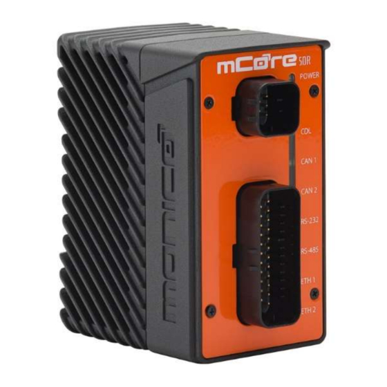
Section 2: Introduction mCore is designed for industrial applications requiring protocol translation between CDL (CAT® Data Link), SAE J1939, Allen Bradley Tags, Modbus RTU, Modbus TCP, and OMF (OSIsoft® Message Format). Each unit comes to you preconfigured and ready to install. The mCore is easy to mount, with two mounting options, and environmentally sealed to protect against dust ingress and temporary immersion in up to 1 meter (IP66 &... -
Page 7: Section 2.1: Led Indicator Table
Section 2.1: LED Indicator Table mCore LED Indicators Solid Green Blinking Green Solid Amber Blinking Amber Solid Red Blinking Red LED Off Key-switch Has Final Shutdown Unit Does Powered On, Booted Powered On Initiated Shutdown Power Sequence and Initial Not Have Up, and Ready to Use and Booting Up or Software... -
Page 8: Section 3: Installation
Section 3: Installation mCore is approved for Class I Div. 2 Group A, B, C, and D. In order to maintain this rating, the unit must be installed in a separate tool secured enclosure and comply with the one of the following NEC wiring methods: 1. -
Page 9: Section 3.1: Mounting
Section 3.1: Mounting DIN Rail Mount: The mCore unit should be mounted vertically on a horizontal DIN rail. Tilt the unit to a 45-degree angle and insert the top lip of the DIN rail bracket onto the DIN rail. While pushing down, attach the bottom lip to the DIN rail to snap the unit into place, as illustrated in Figure 1. - Page 10 Surface-Mount: The unit should be mounted securely against a flat surface, using two ¼” fasteners (not provided), in a suitable location as close to the engine as possible. DO NOT mount directly to the engine block. The unit should be mounted, as shown in Figure 3, either horizontally or vertically.
-
Page 11: Section 3.2: Wiring
The above pinout is depicting the female header connectors and respective key orientations on your mCore that will mate to the male connectors. Monico recommends connecting mCore to the batteries when available so that mCore will be booted up before the engine is turned on so it can capture the startup process. mCore takes about 15 seconds to boot up. - Page 12 Be sure to follow the AMPSEAL “How-to Instructions” located at: https://laddinc.com/resources/how-to-instructions/ampseal-connectors/ https://laddinc.com/resources/how-to-instructions/ampseal-16-contact-crimping/ These instructions include steps for proper inserting, crimping, & removing of wires into the pin connectors. For proper hand crimping, an AMPSEAL 2119118-1 hand crimping tool (not included) must be used. Plugging In: To connect power to the mCore, push the connector until you hear the click of the locking ear snapping into place.
-
Page 13: Section 3.3: Grounding
Section 3.3: Grounding After mounting and connecting mCore, the unit must be grounded in compliance with local and national electrical codes. It must be externally grounded using a customer-supplied ground wire before any power is applied. Contact the appropriate electrical inspection authority if you are uncertain that suitable grounding is available. -
Page 14: Section 4: Parts
Section 4: Parts Section 4.1: Parts Table Connection Parts (AMPSEAL*) Item Description AMPSEAL Part Number Plug, 8 Pin, Key 776286-1 Connector A Plug, 35 Pin, Key 776164-1 Connector B Sealing Plug** 770678-1 Back shell, 8 Pin 2138529-1 Back shell, 35 Pin 776463-1 Connector 770854-1... -
Page 15: Section 5: Power Requirements
Section 5: Power Requirements The input voltage requirements are 8 – 48 VDC for operating temperatures between - C and +65 C. The input voltage requirements are limited to 8 – 28 VDC for operating temperatures between -40 C and +70 C. -
Page 16: Section 6: User Interface
Section 6: User Interface The mCore has a web-based UI (User Interface) for configuring the unit that can be accessed using a web browser. Your mCore User Interface can be accessed via an Ethernet connection. There are two methods for accessing the User Interface for the mCore over an Ethernet connection;... -
Page 17: Section 6.1: Connecting To The User Interface
Section 6.1: Connecting To The User Interface Default Configuration: 1. Plug the mCore’s Ethernet 1 directly into your computer or network switch using an ethernet cable. Ethernet 1 is configured as a static IP. 2. To connect to a static IP address, you will need to make sure your computer’s IP address is setup properly. - Page 18 Example: If the mCore serial number is mc-1234-5678, you would enter, without quotes, “http://mc-1234-5678.local” or “https://mc-1234-5678.local”. 5. You should now see the mCore Login page. Default Username: admin Default Password is unique per mCore and will be on the label sticker on the bottom of the mCore.
-
Page 19: Section 6.2: Setting Computer's Network Adapter
Section 6.2: Setting Computer’s Network Adapter Static IP The section is only needed if connecting to an mCore that previously had its IP address set to be static instead of DHCP. You will need to change your computer’s IP address to be on the same subnet. 1. - Page 20 5. Select the “Use the following IP Address” option. 6. Enter an IP Address where the last number is different from mCore’s, then hit Tab. Example: use the IP depicted above. 7. Enter a Subnet Mask. Typically, it is: 255.255.255.0. Then hit Tab. 8.
- Page 21 DHCP Settings 1. Select Start, then select Settings > Network & Internet > Ethernet. 2. Select Change Adapter Options. 3. Select the Ethernet adapter from the list, and Right Click, select Properties. 4. Select Internet Protocol Version 4 (TCP/IPv4), click Properties. Page 21 of 110 Rev.
- Page 22 5. Select the “Obtain an IP address automatically” option. 6. Click OK to save, then Close to save. Page 22 of 110 Rev. G...
-
Page 23: Section 6.3: Change Password
Section 6.3: Change Password 1. To change the password, click the Account button in the top right, then click Set Password. 2. The following screen will appear. Enter the new password in each box. Click the Set Password button in the center menu when done. 3. -
Page 24: Section 6.4: Account Sign Off
Section 6.4: Account Sign Off Account Sign Off allows you to log off the mCore and requires you to re-enter your login username and password to log back in. 1. To Sign Off, click the Account button in the top right, then click the Sign Out button as shown in the following picture. -
Page 25: Section 6.6: Firewall
Section 6.6: Firewall The mCore’s Firewall give the user the ability to limit inbound connections. This is done by limiting what ports can be accessed on the mCore. Once the Firewall is enabled, no incoming connections will be allowed unless you enter a new rule in the Firewall section to allow the connection to a specific port. - Page 26 2. To enter a new rule, click the LAN rules tab in the center menu. Then click the Add Rule button in the top right of the center menu. The following screen will appear. 3. The Enable check box should be defaulted to checked, if not, check it. Enter a name for the rule and then enter the Port number that you would like allowed an incoming connection to.
-
Page 27: Section 6.7: To Change The Ip Address And Related Settings
Section 6.7: To change the IP address and related settings 1. Click the Ethernet 1 (LAN) button in the left menu toward the top. The following screen will appear. Change the IP address and Subnet to the desired settings. Click the Store Changes button in the center menu at the bottom right. - Page 28 4. Once you’ve entered your IP Address and stored changes, you will need to Commit All Changes for the new IP address to take effect. Do this by clicking the Commit All Changes button in the left menu toward the bottom. Make sure to check the box to include the new network setting changes.
-
Page 29: Section 7: Web Server
“http://mc-1234-5678.local” or “https://mc-1234-5678.local”. This will take you to the Login page. If you are unable to connect, contact Monico Support. 1. The Unit Name will show as Default out of the box, which is the mCore’s serial number. -
Page 30: Section 7.2: Ssl And Http Redirect
2. Enter the new name in the Unit Name box. Click the Store Changes button in the center menu when done. 3. To activate the changes, you will have to click the Commit All Changes button in the left menu towards the bottom. It will show a pop box. Click Ok to continue. -
Page 31: Section 7.3: Upload Ssl Certificate
If allow the mCore to generate its certificate, it will sign this certificate using its own copy of the Monico Local Root certificate. This means that downloading the Monico Local Root and installing on your PC as a Trusted Root will allow your web browser to accept any certificate created by an mCore device. -
Page 32: Section 7.4: External Ip And External Name
3. When done, click the Store Changes button in the center menu. To activate the changes, you will have to click the Commit All Changes button in the left menu towards the bottom. It will show a pop box. Click Ok to continue. mCore will then reboot. - Page 33 2. When done, click the Store Changes button in the center menu. To activate the changes, you will have to click the Commit All Changes button in the left menu towards the bottom. It will show a pop box. Click Ok to continue. mCore will then reboot.
-
Page 34: Section 8: Protocols
Section 8: Protocols Section 8.1: Adding A Protocol 1. To add a protocol, click the Add Protocol button under the section Protocols in the left menu and the following pop up box will appear. Name the protocol and select the protocol from the drop-down menu. Once named and the protocol selected, click Add Protocol. -
Page 35: Section 8.2: Cdl
2. Once you’ve clicked Add Protocol, the protocol will show up under the Protocols section in the left menu. 3. Click the name or the arrow beside the protocol name to expand list and select the next level that appears. This will take you to the protocol setup section. Refer to the relevant protocol sections that follow this section for further setup instructions. - Page 36 1. After adding the Protocol per the Add Protocol section, click the second level of the protocol. 2. mCore automatically scales and converts the CDL data to the units of your choice. Choose between US Units (psi, °F, etc.) or Metric (kPa, °C, etc.). 3.
- Page 37 7. Click the Store Changes button when done. 8. Click the Devices tab. The following screen will appear. To add a parameter to an existing or blank CDL configuration, click the Add Parameter button located in the center menu. A blank parameter screen will appear on the right side. 9.
-
Page 38: Section 8.2.1: Cdl Traffic Log
Section 8.2.1: CDL Traffic Log This is a diagnostics tool for Monico Support staff should the need arise. If asked to get a CDL Traffic Log, follow the steps below for enabling the Traffic Log. With CDL it is important to follow a specific procedure to gather adequate traffic logs. -
Page 39: Section 8.3: Modbus Setup
Section 8.3: Modbus Setup Modbus Theory of Operations: Modbus RTU is a Single Master, but multiple slave protocol that is always a poll/response where the master sends a poll request and nothing else happens until the slave responds or a timeout setting is reached. Modbus TCP simply updated the protocol to work over TCP/IP Ethernet and added the ability to have multiple masters polling slave devices. - Page 40 2. Choose the desired port, either 485 or 232 depending on the application. 3. Once the port is chosen, other settings will appear. Make sure these settings match the settings of the device(s) that mCore will be communicating with. Click Store Changes button at the bottom right when you are done. Page 40 of 110 Rev.
- Page 41 4. Click the Devices tab, then click the Add Devices button. A similar screen to below, depending on the Modbus protocol, will appear. When you are done, click the Add Device button at the bottom right. If you have multiple devices, repeat this step.
- Page 42 5. Once the device is added, a Add Group button will appear under the Add Device button. Click Add Group. The following will appear. Here you will choose the data type (word, real/float, or long), the direction (read or write), the function code (currently only function codes 3 and 4 are supported), and the starting address of the Modbus Register.
- Page 43 6. The button Add Parameter will appear under the Add Group button in the top left as shown. Here you can start mapping out the individual registers starting at the number specified at the group settings in the above step. If this was a Slave application, the Source Data Pool drop down menu would be where you choose the parameter from a different protocol to map out.
-
Page 44: Section 8.4: Sae J1939 Setup
Section 8.4: SAE J1939 Setup S.A.E. J1939 Theory of Operations: J1939 is one of many protocols that run on a CANbus network. J1939 is primarily a broadcast protocol where there are a very large number of Parameter Group Numbers (PGN) and each PGN is assigned a number of Suspect Parameter Numbers (SPN) which are publicly defined and maintained by S.A.E.org. - Page 45 2. Click the Devices tab, then click the Add Device button. Here you can name the device, change the device drop number, and allow DTC clearing. When done, click the Add Device button in the bottom right. 3. Next click the Add Group button that appeared under device name. A pop-up window will appear.
-
Page 46: Section 8.4.1: J1939 Traffic Log
Section 8.4.1: J1939 Traffic Log This is a diagnostics tool for Monico Support staff should the need arise. If asked to get a J1939 Traffic Log, follow the steps below for how to enable the Traffic Log. To export the Traffic Log, see Section 13.6. -
Page 47: Section 8.5: Omf
2. Click the Store Changes button when done. You must then click the Commit All Changes button in the left menu towards the bottom for the change to take effect. Section 8.5: OMF OMF Theory of Operations: OMF (OSIsoft® Message Format) is a data transfer protocol developed to allow individual devices to send data to the PI Server directly without the need for an intermediary Interface or Connector device. - Page 48 met the reporting requirements, it is immediately time-stamped and sent to a memory buffer. If a connection is currently available, the message goes out. If not, the message is buffered with the original timestamp and transmitted when a connection is reestablished.
- Page 49 4. If you are using a Customer Supplied PI Server, enter the PI Server Port Number. If you are using MonicoLive, it will be filled in and un-editable. 5. The PI Server Producer Token is a security code for the data to be able to get into the PI Server.
- Page 50 10. Click Devices Tab in the center menu. Then click the Add Device button. You will see the following screen. Name the device and click Add Device. 11. Next you will see a Add Group button appear under the Add Device button. Click Add Group.
- Page 51 15. Next click Add Parameter in the center menu. The following screen will appear. Choose from the Source Data Pool drop down menu the tag previously created from other protocols that you would like to send to the PI Server. The Label will autofill with the same name as the Source Data Pool but can be changed if desired.
-
Page 52: Section 8.6: Ab Tag Client
2. Select the ethernet port that the mCore will be communicating with the PLC Note: The Software Logs tab should only be used if Monico Technical Support asks you to turn it on to help troubleshoot a problem. It does not provide customer Page 52 of 110 Rev. - Page 53 accessible information. It is strictly a troubleshooting tool. 3. Click the Devices tab, click the Add Device button. You will see the following screen. 4. Give the device a name, then enter the PLC’s IP address. 5. The Slot Number does not matter for CompactLogix PLCs so leave it as 0. If you are using a ControlLogix PLC, enter the slot number of the processor module.
- Page 54 8. Next, click the Add Group button in the center menu towards the left under the device added previously. The following screen will appear. 9. Name the group of parameters you will be adding in the Group Name. It is a good practice to make the Group Name the same as the Array Tag Name to prevent confusion.
- Page 55 12. The Periodic Update Mode is a send-on-change mode with a Poll Frequency that limits how many changes will be sent in each time interval. mCore is checking for change as fast as it can and will send a value when a change occurs but will not send changing values any faster than the Poll Frequency setting.
-
Page 56: Section 8.7: Mqtt Protocols
16. The index numbering is automatic, so starting with 0, you will start adding your parameters to each index number by using the drop-down menu labeled Source Data Pool. Navigate through this drop-down menu, then click the desired parameter. 17. You can also apply a gain/multiplier and offset to the value before it is sent to the PLC as well as choose between signed and unsigned when relevant. -
Page 57: Section 8.7.1: Mqtt-Generic
If a publisher publishes a topic to a broker, but the subscriber is not online, the message can be lost unless there is a specific setup to buffer that topic for that subscriber. Section 8.7.1: MQTT-Generic Generic MQTT is designed to be rather flexible implementation with a JSON payload that is relatively simple. - Page 58 2. When you create a device, this will create a topic. If you want to publish more than one topic, you simply create more than one device. 3. In the Device setup screen there are numerous settings: a. Device Name: This name is for User Interface only and has no significance as to the topic name.
- Page 59 e. Client ID: This is a value included in the header of each message. It is used as part of the default topic name. In addition, it can just be used by the broker to help identify a publisher. If left at Default, mCore’s serial number will be used.
- Page 60 level can slow data flow considerably depending on the network latency, especially when replaying buffered data. iii. 2=Send Exactly Once by using a more complex acknowledge mechanism. Note that this ensures you will get the packet ONLY ONCE, but it also slows down the data flow even more. n.
- Page 61 i. Periodic Async: This method sets an update period where during this period each value will be continuously checked for exception. If a parameter meets the exception test, it is sent immediately no matter where it happens inside the update period. In this mode, you may get a message anytime during the update period, but you will never get a message more often than once every period.
- Page 62 Send on Connect: This setting controls whether to send data immediately upon connection. Enable or Disable. Update Policy: This sets the policy determining what values in a group are sent when an exception is met: i. Send Only Changes: This policy is most common and means that upon each evaluation of the group, only parameters that have met the exception will be time stamped and sent.
-
Page 63: Section 8.7.2: Mqtt Amazon Web Services
l. Buffering File Limit: Allows you to choose the amount of memory dedicated to buffering. Keep in mind that you if you use Data Logging, it will take some memory as well. Section 8.7.2: MQTT Amazon Web Services MQTT-Amazon Theory of Operations: This version of MQTT is a JSON payload format that is very similar to the Generic version. - Page 64 1. Driver Setup is very straight forward where you name the protocol anything you wish. This name is only for the User Interface and does not affect the topic name. Choose which Ethernet port you would like to use. 2. When you create a device, this will create a topic. If you want to publish more than one topic, you simply create more than one device.
- Page 65 b. Broker Address: There are two slots for Broker Addresses. mCore will try to open a connection to Broker Address 1 and then will cycle to Broker Address 2 based on the settings described in more detail below. c. Transport: This protocol can be use on unencrypted TCP/IP or you can choose TLS-SSL.
- Page 66 get a packet once, but it could be received MORE than once. This level can slow data flow considerably depending on the network latency, especially when replaying buffered data. iii. 2=Send Exactly Once by using a more complex acknowledge mechanism. Note that this ensures you will get the packet ONLY ONCE, but it also slows down the data flow even more.
- Page 67 b. Update Mode: This option indicates how the entire group will be processes for exception reporting. Setting are: i. Periodic Async: This method sets an update period where during this period each value will be continuously checked for exception. If a parameter meets the exception test, it is sent immediately no matter where it happens inside the update period.
- Page 68 e. Update Acknowledgement: This sets the acknowledge that the group has triggered and can be reset to rearm the triggered group for the next triggered event. Send on Connect: This setting controls whether to send data immediately upon connection. Enable or Disable. Update Policy: This sets the policy determining what values in a group are sent when an exception is met: i.
-
Page 69: Section 8.7.3: Mqtt-Sparkplug B
ii. To Disk: Buffers data to the eMMC non-volatile storage. Considerably slower, but easily fast enough for most applications. l. Buffering File Limit: Allows you to choose the amount of memory dedicated to buffering. Keep in mind that you if you use Data Logging, it will take some memory as well. - Page 70 1. Driver Setup is very straight forward where you name the protocol anything you wish. This name is only for the User Interface and does not affect the topic name. Choose which Ethernet port you would like to use. 2. When you create a device, this will create a topic. If you want to publish more than one topic, you simply create more than one device.
- Page 71 3. In the Device setup screen there are numerous settings: a. Device Name: This name is for User Interface only and has no significance as to the topic name. b. Broker Address: There are two slots for Broker Addresses. mCore will try to open a connection to Broker Address 1 and then will cycle to Broker Address 2 based on the settings described in more detail below.
- Page 72 m. Keep Alive Period: If there are no packets sent within this time, mCore will send a small packet to keep the connection open and prevent disconnection from the broker. n. Initial Backoff: If mCore cannot establish a connection with the broker it will back off for this time period and then try again.
- Page 73 a. Group Name: This name is only for the User Interface to reference. b. Update Mode: This option indicates how the entire group will be processes for exception reporting. Setting are: i. Periodic Async: This method sets an update period where during this period each value will be continuously checked for exception.
- Page 74 Request is an edge-sensitive trigger for an update, and Update Acknowledgement is the response telling the system it triggered. This group will not be processed again until the trigger is reset to zero and then returns to non-zero once again. c.
-
Page 75: Section 9: Live Data Viewer
and contents of this transmissions will depend on whether each parameter has already changed within the specified period. i. Send Anchors: This feature causes not only the value that met the exception for a parameter to be sent, but also the previous value it was compared to during the evaluation. - Page 76 1. To view live data, select any protocol in the left menu. Click the secondary level to show the center menu, then click the Devices tab as shown below. 2. Next click the group, in this example the PGN name, that contains the parameters you would like to see data for.
- Page 77 3. Click the Show Live Data button in the center menu toward the bottom. A table of the parameters and values will appear. See example below. 4. To stop watching live data, click the Hide Live Data button in the center menu. Page 77 of 110 Rev.
-
Page 78: Section 10: Internal Tags
Section 10: Internal Tags 1. Click the Internal Tags button in the left menu. The following screen will appear. Click Add Folder and input a name for the folder. This will serve as an organizational tool. Click the orange Add Folder button to the right of the name box to save and create the folder. - Page 79 3. Once you’ve clicked Add Tag, the following pop up will appear. Click the Conversion drop down menu to see all the different functions that can be used including multiplier/offset for scaling and unit conversion, add 2 tags together, etc. When done, click the Store Changes button in the pop-up window. Note: See Section 10.1: Function Table for examples and full list of functions.
-
Page 80: Section 10.1: Function Table
Section 10.1: Function Table Label Function Label Function Multiplier/Offset (m*Tag1) + o Bitwise AND (Constant) Tag1 & k Reverse Multiplier/Offset (Tag1 – o) / m Bitwise AND (Tag) Tag1 & Tag2 Addition (Constant) Tag1 + k Bitwise OR (Constant) Tag1 | k Addition (Tag) Tag1 + Tag2 Bitwise OR (Tag) -
Page 81: Section 11: Customer Logging
Section 11: Customer Logging 1. Click the Customer Logging button in the left menu. This will bring you to the following screen. Page 81 of 110 Rev. G... - Page 82 2. Click the Add Log File button. Here you can name the log file and adjust the logging settings. The Period is how often, in milliseconds, mCore will record the values of all tags listed for logging. The Samples Per File is the number of samples mCore will keep in one file before it creates and start saving to another file.
- Page 83 4. The following pop up box will appear. You can either use the search bar or navigate through the tree structure to find the tag you want to add. Click the Add button in the pop-up box after selecting the desired tag. 5.
-
Page 84: Section 11.1: Export Customer Logs
Section 11.1: Export Customer Logs 1. Click Export Logs in the left menu under the Customer Logging section. The following screen will appear. Page 84 of 110 Rev. G... - Page 85 2. Click the Export Now button in the bottom right. The following “Click HERE” blue link will appear. Click this link. A pop-up box will appear asking where you want to save the zip file and what to name it. 3.
-
Page 86: Section 12: Aci Ercm™ Express Configuration
Section 12: ACI eRCM™ Express Configuration Monico has partnered with ACI to provide the hardware for running eRCM Express™ Compressor Modeling software. This program communicates with a PLC and runs the modeling software using compressor and engine data. mCore communicates with the PLCs either over Modbus TCP or using our AB Tag Client to speak directly to an Allen Bradley PLC using Tag Arrays. - Page 87 2. To add a License file from your computer, click the Select File button. A pop up will appear with File Explorer. Navigate to where the License File is located on your computer, select it, then click Open in the bottom right. 3.
-
Page 88: Section 12.2: Viewer File(S)
Section 12.2: Viewer File(s) 1. Click Viewer Files under ACI Configuration in the left menu. The following screen will appear. 2. Click one of the Select File buttons. A pop up will appear with File Explorer. Navigate to where the Viewer File is located on your computer, select it, then click Open in the bottom right. - Page 89 3. The Viewer File will then appear in the screen shown below. Click the check box next to the Viewer File that you want to be active. Multiple Viewer files can be present at one time but only one can be set to active at a time. However, if only 1 file is uploaded and clicked to be Active, it will not be able to be set to inactive until at least a 2nd Viewer file is uploaded.
-
Page 90: Section 12.3: Modbus Tcp Slave - Plc Setup And Sequence Of Operations - Version 1.0 And 1.1 Legacy
Section 12.3: Modbus TCP Slave – PLC Setup and Sequence of Operations – Version 1.0 and 1.1 Legacy Note: mCore will not perform calculations unless a License file AND at least 1 Viewer file is uploaded, set to active, and clicked Store Changes. This version will work the same way as the older firmware version of mCore running V.5 or V1.0. -
Page 91: Section 12.4: Modbus Tcp Slave - Plc Setup And Sequence Of Operations - Version 1.1
Section 12.4: Modbus TCP Slave – PLC Setup and Sequence of Operations – Version 1.1 Note: mCore will not perform calculations unless a License file AND at least 1 Viewer file is uploaded, set to active, and clicked Store Changes. 1. -
Page 92: Section 12.5: Ab Tag Client - Plc Setup And Sequence Of Operations
Section 12.5: AB Tag Client - PLC Setup and Sequence of Operations Note: mCore will not perform calculations unless a License file AND at least 1 Viewer file is uploaded, set to active, and clicked Store Changes. 1. The PLC Programmer will need to first setup their PLC with the following Tag Arrays. -
Page 93: Section 13: System Functions
3. Then ACI_PLC_ACK[0] will go to a 1, meaning the calculations are running and to standby. 4. Then ACI_PLC_ACK[1] will go to a 1 when the calculation is done. 5. Once you receive the 1 from ACI_PLC_ACK[1] for the calculations being done, write a 0 to ACI_PLC_REQ[0], then wait for ACI_PLC_ACK[1] to go to 0. - Page 94 prior to clicking the Commit All Changes button. 1. Once you’ve made your changes, click the Commit All Changes button in the left menu toward the bottom. The following screen will appear. Click the Commit and Reboot button in the center menu. A pop-up box will appear warning the user that the mCore will repeat and lose communications.
-
Page 95: Section 13.2: Restore Last Commit
Section 13.2: Restore Last Commit Restore Last Commit is essentially an undo button. It allows the user to go back to the last Committed configuration. Anything entered, changed, and/or stored will be lost and reset to what was Committed last. 1. -
Page 96: Section 13.3: Export User Data
Section 13.3: Export User Data Exporting User Data will give the customer the ability to create a backup of their mCore’s configuration/settings, share their setup for troubleshooting purposes, or even use it to setup another mCore that is being used for an identical application. 1. - Page 97 2. Click the Export Now button in the center menu. The following screen will appear. 3. Click the blue link labeled “Here”. A pop-up box will appear asking where to save the User Data file and what you want to name it. Click Save when done. Note: Keep in mind if this file is to be used on another mCore on the same network, the IP address and related network information of the old mCore will be in this User Data file.
-
Page 98: Section 13.4: Import User Data
Section 13.4: Import User Data 1. User Data is the configuration database that contains all the settings in the UI (User Interface). The user can import User Data files that were either saved as a backup previously or import User Data files sent with changes. Typical changes would include parameter mapping changes like for Modbus registers or even adding an entire protocol can be done quickly by being sent an already done User Data file and importing it. - Page 99 3. Click the Select File button in the center menu. A pop-up box will appear. Navigate to the saved User Data file, select it, then click Open. User Data files are the file type “.mcore1” on the end of the file. 4.
- Page 100 5. It may take up to about 10 seconds for the file to import and show all the information on the screen. Once it is done, you will see your new changes present. Double check your network settings after every User Data import. Since it copies all settings, it could have incorrect IP address settings copied from an office computer that are incompatible with the site network where the mCore is installed.
-
Page 101: Section 13.5: Clear User Data
Section 13.5: Clear User Data Clear User Data is a quick way to clear out the settings/configuration of the mCore to an empty state. This will remove all protocols, tags, and reset the IP credentials back to a factory reset of 192.168.10.220 on Ethernet 1 and DHCP for Ethernet 2. -
Page 102: Section 13.6: Export System Logs
Section 13.6: Export System Logs System logs are what we call Traffic Logs of RAW data at the driver level. The current protocols that support this feature are SAE J1939 and CDL. The logs are enabled by selecting the Traffic Logs tab under the protocol and enabling the logs by clicking the check box. - Page 103 2. Click the Export Now button in the middle menu. The following screen will appear. Click the blue hyperlink labeled “HERE”. A pop-up box will appear asking where you want to save the log file and what to name it. Click Save. a.
-
Page 104: Section 13.7: Set Device Time
Section 13.7: Set Device Time This feature offers the ability to set the real-time clock (RTC) manually if an NTP server is not available to automatically and regularly updating the clock. The RTC will naturally drift over time, so manually setting it is not a long-term solution if the accurate time stamps are important. - Page 105 Page 105 of 110 Rev. G...
- Page 106 2. Select the file that want you to upload. All firmware updates will have the suffix .img in the filename i.e. mcore-0.6.018.img. After selecting the file, click Open to begin the upload process. Page 106 of 110 Rev. G...
- Page 107 3. Once the file has completed the upload 100%, click UPDATE NOW to begin the upgrade process. Page 107 of 110 Rev. G...
- Page 108 4. You will then be prompted with a warning that you are about to upgrade your firmware. Click OK to continue. DO NOT REMOVE POWER WHILE THE mCORE IS UPDATING FIRMWARE. 5. While the firmware upgrade is in progress, you will see the following message. It will take approximately four (4) minutes for the upgrade to complete, at which time the mCore will automatically reboot and the screen with refresh back to the initial landing page.
-
Page 109: Section 14: Factory Reset
All protocols and other settings will not appear after initial reboot. To get the previous configuration back, click the Restore Last Commit button. Contact Monico Support should you have questions or need assistance with performing this reset. - Page 110 Push the wire through the waterproof gasket at Pins 4 and 5 where the seal plugs were removed on the Power Connector - Key Connector A until you bottom out. The pin out is shown in Section 3.2. While applying gentle force on the jumper wire to make sure the wire maintains contact with both Pins 4 and 5, power on the mCore.
Need help?
Do you have a question about the mCore SDR and is the answer not in the manual?
Questions and answers