Table of Contents
Advertisement
Available languages
Available languages
Installation Instructions and Operator's Manual
WARNING! IF THE INFORMATION IN THIS MANUAL IS NOT FOLLOWED EXACTLY, A FIRE
MAY RESULT CAUSING PROPERTY DAMAGE, PERSONAL INJURY OR LOSS OF LIFE.
Made in China
This heater should be installed by qualified persons only and in accordance with the
National Electric Code (Canadian Electrical Code in Canada) and all applicable local
codes. Supply wiring must be copper and suitable for at least 75° C.
EWH5500- minimum 10 gauge SJO or SJTO copper type wiring required
EWH9600- minimum 6 gauge SJO or SJTO copper type wiring required.
This product contains chemicals including di(2-ethylhexyl)phthalate (DEHP), which is known to the State of
California to cause cancer and reproductive harm. For more information, go to: www.P65Warnings.ca.gov
UL 2021. FIXED AND LOCATION –DEDICATED ELECTRIC ROOM HEATERS
Comfort Home Products, Inc.
12256 William Penn Hwy, Ste A
Huntingdon, PA 16652
DURA HEAT PHONE NUMBER:
http://www.worldmkting.com
CALIFORNIA RESIDENTS ONLY-WARNING:
DO NOT DISCARD THIS MANUAL
CUSTOMER: PLEASE RETAIN THIS MANUAL FOR FUTURE USE
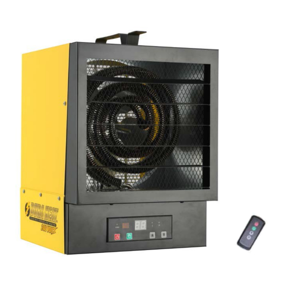
EWH5500 / EWH9600
Garage & Utility
Electric Heater
OTHER FLAMMABLE VAPORS
(800) 776-9425
IN THE VICINITY OF THIS OR
ANY OTHER APPLIANCE
FOR YOUR SAFETY
DO NOT STORE
OR USE GASOLINE OR
OR LIQUIDS
Advertisement
Table of Contents

Subscribe to Our Youtube Channel
Related Manuals for Dura Heat EWH5500


Summary of Contents for Dura Heat EWH5500
- Page 1 National Electric Code (Canadian Electrical Code in Canada) and all applicable local codes. Supply wiring must be copper and suitable for at least 75° C. EWH5500- minimum 10 gauge SJO or SJTO copper type wiring required EWH9600- minimum 6 gauge SJO or SJTO copper type wiring required.
-
Page 2: Important Instructions
IMPORTANT INSTRUCTIONS PLEASE READ AND SAVE THESE IMPORTANT SAFETY INSTRUCTIONS WHEN USING ELECTRIC APPLIANCES, BASIC PRECAUTIONS SHOULD ALWAYS BE FOLLOWED TO REDUCE THE RISK OF FIRE, ELECTRIC SHOCK, AND INJURY TO PERSONS, INCLUDING THE FOLLOWING: 1. Read all instructions before using this heater. 2. -
Page 3: Specifications
(All Specifications -5%/-10% tolerance) Model No Volts/Hertz Amps Watts BTU/HR Phase Minimum Circut EWH5500 240V/60HZ 5000 17060 EWH9600 240V/60HZ 10000 34120 To prevent a possible fire, injury to persons or damage to the heater, adhere to the following: 1. Disconnect all power coming to heater at main service panel before wiring or servicing. -
Page 4: Installation Instructions
INSTALLATION INSTRUCTIONS TOOLS NEEDED: • Phillips head screwdriver • 5/32 in. or 4 mm drill bit • Power Drill • Stud Finder • The remote control is powered by 2 AAA batteries. Batteries are NOT included HARDWARE REQUIRED FOR WIRING HEATER: •... -
Page 5: Wall Mounting
INSTALLATION INSTRUCTIONS MOUNTING: Figure 4 Figure 5 WALL MOUNTING CEILING MOUNTING DETAILED BRACKET ASSEMBLY ILLUSTRATION MINIMUM CLEARANCES: Figure 6... -
Page 6: Heater Mounting
INSTALLATION INSTRUCTIONS WARNING: Fall Hazard - Heater must be attached to a joist with 3 screws (two at keyhole slots and • third safety screw at center hole) to prevent heater from possibly falling. The screws provided with heater are intended for installing in wood framing only and not intended for metal joists or other types of construction. -
Page 7: Wiring Instructions
WIRING INSTRUCTIONS After heater has been properly mounted Heater is provided with a 28.3mm hole into wiring compartment for routing of branch circuit conductors. to the building structure and appropriate Appropriate conduit and fittings must be provided for branch circuit wiring has been routed to correct and safe installation. - Page 8 WIRING INSTRUCTIONS...
- Page 9 To change from Heat to Fan or Fan to Heat, use the UP or DOWN Arrow buttons. After approximately 5 seconds the control will then be programmed for the selected output. (For model EWH5500) Adjusting Power Level: While the unit is ON, push the green mode button once. This will activate the power selection mode and the red light over the “L”...
-
Page 10: Maintenance
OPERATING INSTRUCTIONS NOTE: The first time you operate the unit, it may smoke slightly. This is due to the residual cleaning agents used to clean the element when the heater is manufactured. This is normal and does not indicate a problem with the unit. -
Page 11: Troubleshooting & Warranty
TROUBLESHOOTING & WARRANTY PROBLEM CAUSE SOLUTION Fan stays on when heat shuts off. 1. Fan delay cycles On/Off until 1. Heater is operating correctly. elements are cool Heating element does not glow 1. Heating element is made of 1. Heater is operating correctly. stainless steel and will not glow red to produce heat. -
Page 12: What Is Not Covered
TROUBLESHOOTING & WARRANTY WHAT IS NOT COVERED: Damage caused by misuse or use contrary to the owner’s manual and safety guidelines. Damage caused by a lack of normal maintenance. Repair by an unauthorized person. Damage caused by connection to an improper voltage. Damaged caused by use outdoors. -
Page 13: Para Su Seguridad
Eléctrico Nacional (Código Eléctrico Canadiense en Canadá) y todos los códigos locales aplicables. El cableado de suministro debe ser de cobre y apto para al menos 75 °C. EWH5500- minimum 10 gauge SJO or SJTO copper type wiring required EWH9600- minimum 6 gauge SJO or SJTO copper type wiring required. -
Page 14: Instrucciones Importantes
INSTRUCCIONES IMPORTANTES AL USAR APARATOS ELÉCTRICOS, LEA Y CONSERVE ESTAS INSTRUCCIONES DE SEGURIDAD IMPORTANTES SE DEBEN TOMAR PRECAUCIONES BÁSICAS PARA REDUCIR EL RIESGO DE INCENDIO, DESCARGAS ELÉCTRICAS Y LESIONES A LAS PERSONAS, INCLUYENDO LO SIGUIENTE: 1. Lea todas las instrucciones antes de usar el calentador. 2. - Page 15 ESPECIFICACIONES (Todas las especificaciones tienen -5 %/-10 % de tolerancia) Circuito Modelo No Voltios/Hertz Amperios Vatios BTU/HR Phase mínimo EWH5500 240V/60HZ 5000 17060 EWH9600 240V/60HZ 10000 34120 Para evitar un posible incendio, lesiones a personas o daños al calentador, respete lo siguiente: 1.
-
Page 16: Instrucciones De Instalación
INSTRUCCIONES DE INSTALACIÓN HERRAMIENTAS NECESARIAS: • Destornillador Phillips • Broca de 5/32 pulgadas o 4 mm • Taladro eléctrico • Detector de montantes • El control remoto funciona con 2 pilas AAA. Las pilas NO están incluidas MATERIAL NECESARIO PARA EL CABLEADO DEL CALENTADOR: •... -
Page 17: Montaje En Pared
INSTRUCCIONES DE INSTALACIÓN MONTAJE: Figura 4 Figura 5 MONTAJE EN PARED MONTAJE EN TECHO ILUSTRACIÓN DETALLADA DEL SOPORTE DISTANCIAS MÍNIMAS: Figura 6... - Page 18 INSTRUCCIONES DE INSTALACIÓN ADVERTENCIA: Peligro de caída: El calentador debe sujetarse a una viga con 3 tornillos (dos en los orificios de los extremos y el tercer tornillo de seguridad en el orificio central) para evitar que se caiga. Los tornillos provistos con el calentador están diseñados para ser colocados solo en estructuras de madera y no en vigas metálicas u otros tipos de construcción.
-
Page 19: Instrucciones De Cableado
INSTRUCCIONES DE CABLEADO Después de haber montado correctamente el El calentador cuenta con un orificio de 28,3 mm en el compartimiento de cableado para encaminar los calentador en la estructura del edificio y de conductores del circuito derivado. Deben proporcionarse haber llevado un cableado apropiado desde el conductos y accesorios apropiados para una instalación circuito derivado hasta la ubicación del... - Page 20 INSTRUCCIONES DE CABLEADO...
-
Page 21: Instrucciones De Operación
Use las flechas para cambiar de “Calor” a “Ventilador” o viceversa. Después de aproximadamente 5 segundos, el control se programará para la salida seleccionada. (Para el modelo EWH5500) Ajuste del nivel de potencia: Con la unidad encendida, presione una vez el botón verde. Esto activará el modo de selección de potencia y la luz roja ubicada sobre “L”... -
Page 22: Mantenimiento
INSTRUCCIONES DE OPERACIÓN NOTA: La primera vez que opere la unidad, puede despedir un poco de humo. Esto se debe a los agentes de limpieza residuales que se utilizan para limpiar el elemento cuando se fabrica el calentador. Esto es normal y no indica ningún problema con la unidad. - Page 23 SOLUCIÓN DE PROBLEMAS Y GARANTÍA PROBLEMA CAUSA SOLUCIÓN El ventilador permanece 1. El ventilador retarda su 1. El calentador está funcionando encendido cuando el calentador apagado hasta que los elementos correctamente. se apaga. se enfrían El elemento térmico no se pone 1.
- Page 24 SOLUCIÓN DE PROBLEMAS Y GARANTÍA LO QUE no ES CUBIERTO: El daño causado por maltrato o utiliza al contrario del manual de propietarios y pautas de seguridad. El daño causado por una falta de mantenimiento normal. Repare por una persona no autorizada. El daño causado por conexión a un voltaje impropio.
- Page 25 Le câblage d'alimentation doit être en cuivre et il doit convenir à une chaleur d'au moins 75 °C. EWH5500- minimum 10 gauge SJO or SJTO copper type wiring required EWH9600- minimum 6 gauge SJO or SJTO copper type wiring required.
-
Page 26: Instructions Importantes
INSTRUCTIONS IMPORTANTES VEUILLEZ LIRE ET CONSERVER CES INSTRUCTIONS DE SÉCURITÉ IMPORTANTES LORSQUE VOUS UTILISEZ DES APPAREILS ÉLECTRIQUES, DES PRÉCAUTIONS DE BASE DOIVENT TOUJOURS ÊTRE OBSERVÉES AFIN DE RÉDUIRE LES RISQUES DE FEU, DE DÉCHARGE ÉLECTRIQUE ET LES BLESSURES, Y COMPRIS CE QUI SUIT : 1. - Page 27 SPÉCIFICATIONS (pour toutes les spécifications : tolérance de -5%/-10%) Model No Volts/Hertz Amps Watts BTU/HR Phase Circuit minimum EWH5500 240V/60HZ 5000 17060 EWH9600 240V/60HZ 10000 34120 Pour éviter les risques de feu, de blessures ou de dommages à l'appareil de chauffage, respectez ce qui suit : 1.
-
Page 28: Instructions D'installation
INSTRUCTIONS D'INSTALLATION MATÉRIEL INCLUS : figure 1 OUTILS NÉCESSAIRES : • Tournevis Phillips à tête cruciforme • Mèche de 5/32 po ou 4 mm • Perceuse électrique • Détecteur de colombage • La télécommande est alimentée par 2 piles AAA. Les piles ne sont PAS incluses. MATÉRIEL NÉCESSAIRE POUR LE CÂBLAGE DE L'APPAREIL DE CHAUFFAGE : •... -
Page 29: Installation Murale
INSTRUCTIONS D'INSTALLATION EMPLACEMENT DE L'APPAREIL DE CHAUFFAGE : figure 3 L'appareil de chauffage doit être installé hors des zones de circulation et au moins à 6 pi du plancher. (8 po au-dessus du plancher, pour le Canada) La direction du flux d’air ne doit pas être restreinte (c.-à-d. par des colonnes ou des machines) et le flux d’air doit balayer les parois exposées, plutôt que de souffler directement sur elles. -
Page 30: Installation De L'appareil De Chauffage
INSTRUCTIONS D'INSTALLATION DÉGAGEMENT MINIMUM : figure 6 AVERTISSEMENT : risque de chute : l'appareil de chauffage doit être fixé à une solive avec 3 vis (deux aux fentes piriformes et la troisième vis de sécurité au trou central) pour empêcher l'appareil de tomber. - Page 31 INSTRUCTIONS D'INSTALLATION INSTALLATION DE L'APPAREIL DE CHAUFFAGE : 3. Utilisez la mèche de 5/32 (4 mm) pour prépercer les deux trous 4. Installez deux vis de 2,5 po (65 mm) dans les trous en laissant environ 1/8 po de la vis hors du mur. Assurez-vous que les deux vis soient insérées d'au moins 1,5 po dans le montant ou la solive.
- Page 32 INTRUCTIONS POUR LE CÂBLAGE L'appareil de chauffage est muni d'un trou de 28,3 mm dans le compartiment de câblage pour l'acheminement des conducteurs du circuit de dérivation. Un conduit et des raccords appropriés doivent être utilisés pour obtenir une installation sécuritaire et adéquate. 1.
- Page 33 INTRUCTIONS POUR LE CÂBLAGE...
- Page 34 Pour passer de Ventilateur à Chaleur, utilisez les boutons avec la flèche Haut ou Bas. Après environ 5 secondes, l'appareil sera programmé selon votre sélection. (Pour le modèle EWH5500) Adjusting Power Level: While the unit ON, push the green mode button once. This will activate the power selection mode and the red light over the “L”...
-
Page 35: Entretien
MODE D'EMPLOI REMARQUE : la première fois que vous utilisez l’appareil de chauffage, il peut émettre une légère fumée. Ceci en raison des agents de nettoyage résiduels utilisés pour nettoyer l’élément lors de la fabrication de l'appareil de chauffage. Ceci est normal et n’indique pas un problème avec l’appareil. Cela cessera lorsque l'appareil aura fonctionné... - Page 36 DÉPANNAGE ET GARANTIE PROBLÈME CAUSE SOLUTION Le ventilateur reste allumé 1. Le ventilateur effectue le cycle 1. L'appareil de chauffage lorsque la chaleur s’éteint. Allumer/éteindre jusqu’à ce que fonctionne correctement. les éléments soient refroidis. L’élément chauffant ne vient pas 1. L'élément chauffant est 1.
- Page 37 DÉPANNAGE ET GARANTIE DEVOIRS DU PROPRIÉTAIRE: Cet appareil de chauffage doit fonctionner en accord avec les instructions fournies avec le poêle. Cette garantie ne doit pas dissuader le propriétaire d'un entretien correct du poêle en accord avec les instructions écrites fournies avec ce poêle. Une facture de paiment, un chèque annulé...
Need help?
Do you have a question about the EWH5500 and is the answer not in the manual?
Questions and answers