
Summary of Contents for Yacht Devices YDEG-04
- Page 1 User Manual Yacht Devices Engine Gateway YDEG-04 also covers models YDEG-04N, YDEG-04R Firmware version 1.31 2019...
- Page 2 © 2019 Yacht Devices Ltd. Document YDEG04-011. May 21, 2019. Web: http://www.yachtd.com/ Yacht Devices Engine Gateway YDEG-04 is certified by the National Marine Electronics Association. NMEA 2000® is a registered trademark of the National Marine Electronics Association. SeaTalk NG is a registered trademark of Raymarine UK Limited.
-
Page 3: Table Of Contents
Contents Introduction Warranty and Technical Support I. Product Specification II. MicroSD Slot and Card’s Compatibility III. Installation and Connection to NMEA 2000 Network IV. Connection to Engine Network IV.1 Connection to a Volvo Penta Engine IV.1.1 Connection to EFI Engines (Gasoline, 2004-2005) IV.1.2 Connection to EGC Engines (Gasoline, 2005 and Later) IV.1.3 Connection to EDC III (EMS2), EDC IV (Diesel) IV.1.4 Connection to EVC-A MC (EVC-MC, EVCmc) Engines (2004-2006, Diesel and Gasoline) -
Page 4: Introduction
The YDEG-04 is compatible with a wide range of NMEA 2000 devices. Raymarine SeaTalk NG, Simrad SimNet and Furuno CAN networks are branded versions of NMEA 2000 and differ only in the type of connectors. - Page 5 transceiver of the engine network. The Device is designed to work on 12V or 24V engine networks. The devices is equipped with a slot for a MicroSD card which can be used to configure its settings (loading a text file with the settings), updates for the Device firmware. The card can also serve to record the data from the engine network for configuration and diagnosis of the Device.
-
Page 6: Warranty And Technical Support
Warranty and Technical Support The Device warranty is valid for two years from the date of purchase. If a Device was purchased in a retail store, when applying under a warranty case, the sale receipt may be requested. The Device warranty is terminated in case of violating the instructions of this Manual, case integrity breach, repair or modification of the Device without manufacturer’s written permission. -
Page 7: Product Specification
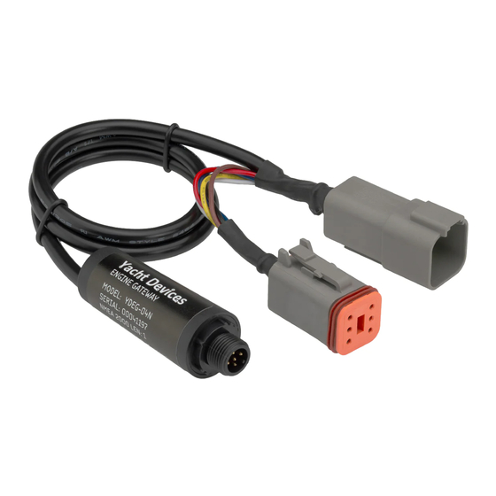
I. Product Specification Figure 1. Drawing of YDEG-04R model of Gateway Our devices are supplied with different types of NMEA 2000 connectors. Models with suffix R at the end of model name are equipped with NMEA 2000 connectors compatible with Raymarine SeaTalk NG (as at the picture above). - Page 8 Device’s case length (without connector) Weight without MicroSD card Yacht Devices Ltd declares that this product is compliant with the essential requirements of EMC directive 2014/30/EU. Dispose of this product in accordance with the WEEE Directive. Do not mix electronic disposal with domestic or industrial refuse.
-
Page 9: Microsd Slot And Card's Compatibility
II. MicroSD Slot and Card’s Compatibility The Device has a slot for a MicroSD card that allows you to configure the Device (see Section V) and update the firmware (see Section VIII). Since the MicroSD slot is usually not in use when the Device is working, we recommend sealing it with the sticker that is included with the Device or with a piece of tape to prevent water from entering the Device through the slot. - Page 10 Figure 1. Device with MicroSD card (pin side visible at left, label side at right) — 10 —...
-
Page 11: Installation And Connection To Nmea 2000 Network
III. Installation and Connection to NMEA 2000 Network The Device requires no maintenance. When deciding where to install the Device, choose a dry mounting location. Avoid places where the Device can be flooded with water, this can damage it. The Device is directly connected to the network backbone without a drop cable. Before connecting the Device, turn off the bus power supply. -
Page 12: Connection To Engine Network
IV. Connection to Engine Network Read and become fully familiar with the contents of this section. Never connect the Device to the connector that ‘just looks right’ until you are sure about its wiring. If you have any doubts, ask a specialist. Modern engine networks may seem very complicated and may have many similar connectors with different wiring and different purposes. -
Page 13: Iv.1 Connection To A Volvo Penta Engine
IV.1 Connection to a Volvo Penta Engine The Device is compatible with all versions of Volvo Penta EVC, including the first version EVC-A (also known as EVC-MC or EVC-EC); engines with MDI (Mechanical Diesel Interface, D1 and D2 series); with engines equipped with EDC III (EMS2) and EDC IV systems; with gasoline engines equipped with EFI system (MEFI4B or MEFI5 controllers are supported, with or without EVC system installed);... -
Page 14: Iv.1.1 Connection To Efi Engines (Gasoline, 2004-2005)
IV.1.1 Connection to EFI Engines (Gasoline, 2004-2005) Only engines equipped with an MEFI4B controller and later are supported (for example, 8.1 Gi-E, 8.1 OSi-A, 8.1 Gi-EF, 8.1 GXi-D, 8.1 GXi-E and many other). An adaptor cable for the Marine Data Link Connector is required (available in accessories on the ordering page). The cable has both male and female connectors (Y-connector), so you can use diagnostics equipment with the Gateway connected. -
Page 15: Iv.1.2 Connection To Egc Engines (Gasoline, 2005 And Later)
IV.1.2 Connection to EGC Engines (Gasoline, 2005 and Later) Note: If an EVC system is fitted, see the EVC section details. The Device is compatible with all EGC engines (8.1Gi-H, 8.1GXi-G, 8.1OSi-D and many other). Device is connecting to EVC/Vodia 8-pin Deutsch connector with adaptor cable (see Appendix F, available in accessories at ordering page). -
Page 16: Iv.1.5 Connection To Evc-A Ec (Evc-Ec, Evcec) Engines (2002-2005)
level. Engine revolutions, coolant temperature, boost pressure, battery voltage and engine hours supported. Engine Gateway must connected series with engine and Helm Interface Unit (HIU). Connections can be made with a «EVC-A MC 12-pin C5:ENGINE» adaptor cable (available in accessories on the ordering page). -
Page 17: Iv.1.6 Connection To Other Evc Versions And Mdi (Engines From After 2005, Evc-B And Later)
One Gateway is enough for a twin-engine installation. Note: you can use the supplied 6-pin plug as a dust cap for the unused Device connector. IV.1.6 Connection to Other EVC Versions and MDI (Engines from After 2005, EVC-B and Later) This connection can be made at the following points (please, read also the details below): •... - Page 18 the Device must be installed in the unused connector of Device. This plug connects the two CAN interfaces (CAN1 and CAN2, see Appendix E). The engine controller sends data on the CAN1 interface and monitors the echo on CAN2. CAN1 and CAN2 are joined in EVC tachometer. If the tachometer is not installed and the plug is not set, the engine controller will see no echo at CAN2 and will stop data transmission.
- Page 19 to the HCU or a hub without an EVC cable, because the required Device connector (female) will be inserted in the HCU/hub. In this case you can contact us before ordering, and we’ll supply you with a female type plug instead of the male type free of charge. You can also join the pins of the female Device connector yourself (CAN1 HIGH with CAN2 HIGH, CAN1 LOW with CAN2 LOW, see Appendix E).
-
Page 20: Iv.2 Connection To Brp Rotax Engines
IV.2 Connection to BRP Rotax Engines BRP CAN protocol differs from J1939 and Volvo Penta EVC protocols and requires configuration of the Device. BRP CAN diagnostics connector wiring is also differ from the Device’s engine connector wiring; you should change the pins in the connector or use an adaptor cable. The Device supports up to two BRP engines on a network. - Page 21 settings to map engines to NMEA 2000 identifiers. The Device will save port engine data for the engine configured with J1939 address 0, and starboard engine data to the engine configured with J1939 address 1. If the data for the port and starboard engines are reversed on the chart plotter’s screen, you must change the default settings to: ENGINE_0=1 ENGINE_1=0...
-
Page 22: Iv.3 Connection To J1939 Engines
IV.3 Connection to J1939 Engines Adaptor cables for some J1939 engines (including Caterpillar and Yanmar) are available. Please, check our web site for current information. The Device works with engines and engine networks using the widespread J1939 standard, which at the physical level is a CAN bus with 250 kbps speed. J1939 is the standard for automobiles, heavy equipment, and industrial engines and generators. -
Page 23: Iv.4 Connection To Smartcraft Engines
IV.4 Connection to SmartCraft Engines The SmartCraft protocol is used in Mercury and MerCruiser engines, and differs from J1939 and Volvo Penta EVC protocols and requires configuration of the Device. The Gateway can be connected to a 10-pin SmartCraft connector with the adaptor Y-cable, available on our website. The Device supports up to four SmartCraft engines on a network. - Page 24 FUEL_3=1,STARBOARD BATTERY_0=1 BATTERY_1=OFF TRIM_ZERO=1800 TRIM_STEP=200 To calibrate electronic tilt/trim sensor, please, see V.37-39. — 24 —...
-
Page 25: Configuring The Device
V. Configuring the Device To configure the Device, a text file with the configuration should be created and named YDEG.TXT in the root folder of the MicroSD card. A sample of the configuration file is in Appendix D. The file contents must conform to these rules: •... - Page 26 Device connected Device connected to the starboard engine to the port engine ENGINE_0=OFF ENGINE_0=0 ENGINE_1=0 ENGINE_1=OFF The value OFF is guaranteed to prevent the transfer of data to the NMEA 2000 network for the given identifier. Engines in the BRP CAN and SmartCraft networks have no J1939 addresses, but this setting is used to identify port and starboard engines.
- Page 27 Factory settings (from x=0 to 7): 0, 1, OFF, OFF, OFF, OFF, OFF, OFF Batteries on the NMEA 2000 network have identifiers analogous to engines. The value, though, is not related to the location or purpose of the battery. For example, on a sailing yacht with a single engine, data on the service battery will be transferred by a special sensor on the NMEA 2000 network.
- Page 28 6. FUEL_x=[y,z|OFF] x — identifier of the fuel tank on the NMEA 2000 network [0..9] y — address of the engine (or other equipment) of the J1939 network, providing data on the level of fuel in the tank [0..254] z — tank [PORT, STARBOARD] Factory setting (from x=0 to 7): {0,PORT}, {0,STARBOARD}, OFF, OFF, OFF, OFF, OFF, OFF, OFF, OFF The engine and other equipment on the J1939 network can send information about two fuel tanks which are nominally counted as the first and second, or left and right, port or starboard (J1939 SPN 96 or SPN 38).
- Page 29 8. MDI_AUX_MASK=x x — 24-bit mask, hexadecimal number 000000…FFFFFF Factory setting: 000000 This parameter controls mapping of the signal of auxiliary sensor of the Volvo Penta MDI (AUX, see VI.1) to the engine’s status in the NMEA 2000 network. For example, if an auxiliary sensor is installed and signals that there is water in the fuel, set the value of the mask in 000100 (hexadecimal number, bit 9 is set) in accordance with the table in Appendix B.
- Page 30 11. ALERT_WARN1_MASK=x x — 24-bit mask, hexadecimal mask, hexadecimal number 000000…FFFFFF Factory setting: 000000 Set bit 17 of the engine status («Warning Level 1») if at least one bit of the current engine status matches the specified mask. Use of this setting is described in VI.5. 12.
- Page 31 15. TRANSMISSION_x=y x — identifier of a transmission on the NMEA 2000 network [0..7] y — address of the transmission on the J1939 network [0..253, OFF] Factory configuration (from x= 0 to 7): 3,4,OFF,OFF,OFF,OFF,OFF,OFF Like a port engine (see V.1), port transmission has an identifier 0 in NMEA 2000; the identifier increase from port to starboard.
- Page 32 To simplify obtaining the calibration string, we prepared an Excel file available on our web site. You only need to specify your gauge's readings and the measured remaining fuel volume to get the calculated calibration string. 18. EXHAUST_TEMP=ON|OFF Factory setting: ON Allows or denies transmission of exhaust gas temperature.
- Page 33 22. WATER_DEPTH_OFFSET=x x – OFF (default value) or a number from -1000 to 1000 Positive numbers (in centimeters) represent the distance from the transducer to the water line and negative values represent the distance from the transducer to the keel. This value is sent as the transducer offset (in separate data field) of the «Water Depth»...
- Page 34 25. INTAKE_MANIFOLD_TEMP=x x – OFF (default value) or a number from 1 to 252 NMEA 2000 has no data type for transmitting intake manifold temperature (supported in Volvo Penta, J1939, SmartCraft and BRP Rotax engines). Moreover, many chart plotters have gauges for a limited set of data types.
- Page 35 26. EDC2=x x – OFF (default value) or ON Turn on or off experimental support of EDC II. Volvo Penta engines with EDC II use a J1939 interface for engine synchronization only. This means that the port engine sends actual revolutions, and the starboard engine listens and synchronizes revolutions.
- Page 36 Factory setting: OFF Different devices in engine and NMEA 2000 networks can have matching addresses. And forwarding of such messages can cause conflicts. To avoid conflicts, YDEG can use its own, original address or a specified address as the sender address in the forwarded messages. This is managed by the PASS_ADDR setting.
- Page 37 31. HOURS_OFFSET=x x - number of seconds, 0..10000000 Factory setting: 0 The number of seconds which are added to engine hours. Some users have replaced ECU and EDC modules, which reports engine hours since installation of module. This setting helps to get real data on gauges. 32.
- Page 38 34. TRANS_ALERT_x=[y,w,z|OFF] x — digit from 0 to 9, internal index of the Device y — 5-bit mask, hexadecimal number 00…1F w — decimal number of SPN, see the manual of your specific engine z — decimal number FMI, from 0 to 31, see the manual of your engine When a diagnostic message (PGN 65226) with specified SPN and FMI codes is received from the engine’s transmission, set the bits of the transmission status in NMEA 2000 according to the mask.
- Page 39 37. TRIM_ZERO=x x – calibration value of 0% tilt/trim position, 0..65534 Factory setting: 28708 The Gateway process three different messages with tilt/trim data depending on the current settings. Switching on/off SMARTCRAFT or MEFI4B setting (V.35-36) resets the value to default for SmartCraft, MEFI or Volvo Penta EVC systems.
- Page 40 If the Gateway actually has tilt/trim data, the value of TRIM_ZERO setting (V.37) will be updated and you will see 3 green confirmation flashes. Then lift the engine to highest position and load the file with the line: CALIBRATE_TRIM=100 The Gateway will calculate trim step corresponding to 1% and update the TRIM_STEP value (V.38). Review V.37-38 settings in the YDEGSAVE.TXT and modify values if required.
- Page 41 For temperature data types, we recommend using Exhaust Gas Sensor YDGS-01. This measures temperatures up to 800 Celsius. The data instance can be configured with a YD:DAT command. For pressure data types, we recommend Tank Adapter YDTA-01. This product is an NMEA 2000 adapter for resistive and voltage sensors, and can work in parallel with analog and digital gauges.
-
Page 42: Display Engine And Transmission Status (Warnings)
VI. Display Engine and Transmission Status (Warnings) The standard NMEA 2000 defines 24 warnings for engine status and 5 for transmission status that are listed in Appendix B. The NMEA 2000 displays and chart plotters can support display of the engine status in different varying degrees. - Page 43 Table 1. continued Symbol Description Status in NMEA 2000 [bit] System fault. Malfunction in engine cables Can be mapped by user (*). (open circuit, short circuit). Auxilary alarm. Triggering of auxiliary Can be mapped by user (*). sensor (if connected; depending on the implementation).
- Page 44 Table 2. Display of J1939 engine and transmission status Engine status display Description in NMEA 2000 [bit] Low fuel pressure 1, 18 Low Fuel Pressure [5] Water in fuel Water in Fuel [9] Low engine oil level Low Oil Level [4] Low engine oil pressure 1, 18 Low Oil Pressure [3]...
- Page 45 Table 3. Supported BRP CAN fault codes Fault Fault Description NMEA 2000 Status Code P0217 High engine coolant temperature Over Temperature [2] P0524 Low oil pressure condition Low Oil Pressure [3] P1520 Low oil level Low Oil Level [4] P0562 Battery voltage too low Low System Voltage [6] P0127 Intercooler system fault...
- Page 46 For example, to map P1030 to «Maintenance Needed», you should place the following line in the configuration file: ALERT_0=080000,4144,0 Where 080000 is the hex mask of «Maintenance Needed» (see Appendix B), 4144 is a decimal equivalent of hexadecimal 1030 (BRP fault codes are hexadecimals), the last number — 0 — can be any value from 0 to 31 (not used).
-
Page 47: Led Signals
VII. LED Signals 1. Signal with period of 5 seconds, two flashes of the LED. The first flash indicates the condition of the engine network. Green if within the last period (5 seconds) data has been accepted from the engine network, red if not. The second flash indicates the condition of the NMEA 2000 network. -
Page 48: Firmware Updates
VIII. Firmware Updates In the root folder of the MicroSD card with FAT or FAT32 file system, copy GUPDATE.BIN, which contains the firmware update of the Device. Insert the card into the Device and turn on the power in the NMEA 2000 network. From 5-15 seconds after powering on, the LED will flash 5 times with green light. - Page 49 Figure 1. Raymarine c125 MFD devices list with Gateway (YDEG-04) — 49 —...
-
Page 50: Recording Data And Diagnostics Of The Engine Interface
IX. Recording Data and Diagnostics of the Engine Interface The Device allows data to be recorded form the engine network to the MicroSD card for the purpose of diagnostics and configuration. Turn the engine ignition off. Create a file called YDEG.TXT with the following line included: ENGINE_LOG=ON Note that the given configuration is not saved in the non-volatile memory and will stop its action after the card is removed or when the NMEA 2000 network is powered off. -
Page 51: Appendix A. Troubleshooting
Appendix A. Troubleshooting Situation Possible cause and correction 1. No power supply on the bus. Check if the bus power is supplied The LED does not signal after NMEA 2000 (NMEA 2000 network requires a separate power connection and cannot network is powered on be powered by a plotter or another device connected to the network). - Page 52 Table continued Situation Possible cause and correction 1. Card is not formatted correctly. Reformat card (see II.). Memory card with YDEG. TXT file is inserted into the 2. Card contains logic error. It is possible for such errors to go Device, but three red lights unnoticed by scanning utilities, recommendation to reformat card.
-
Page 53: Appendix B. Bits For Engine And Transmission Status
Appendix B. Bits for Engine and Transmission Status Table 1. Bits for NMEA 2000 Engine Status (DD206, DD223) Bit number Mask (hex) Meaning 000001 Check Engine 000002 Over Temperature 000004 Low Oil Pressure 000008 Low Oil Level 000010 Low Fuel Pressure 000020 Low System Voltage 000040... - Page 54 Table 2. Bits for NMEA 2000 Transmission Discrete Status (DD221) Bit number Mask (hex) Meaning Check Tranmission Over Temperature Low Oil Pressure Low Oil Level Sail Drive — 54 —...
-
Page 55: Appendix C. Nmea 2000 And J1939 Messages Supported By The Device
Appendix C. NMEA 2000 and J1939 Messages Supported by the Device Table 1. Supported J1939 messages Description 60160 — Transport Protocol — Data Transfer 60416 — Transport Protocol — Connection Mgmt 61443 Electronic Engine Controller 2 / Engine Percent Load At Current Speed 61444 Electronic Engine Controller 1 / Engine Speed 61444... - Page 56 Table 1 continued Description 65271 Vehicle Electrical Power 1 / Charging System Potential (Voltage) 65271 Vehicle Electrical Power 1 / Alternator Current 65271 Vehicle Electrical Power 1 / Battery Potential / Power Input 1 65271 Vehicle Electrical Power 1 / Net Battery Current 65272 Transmission Fluids / Transmission Oil Pressure 65272...
- Page 57 Table 2. Supported NMEA 2000 messages Description 59392 ISO Acknowledgment 59904 — ISO Request 60160 — ISO Transport Protocol (DT) 60416 — ISO Transport Protocol (CM) 60928 ISO Address Claim 65240 — ISO Commanded Address 126208 NMEA Group Function 126464 —...
- Page 58 Note: NMEA 2000 Device Instance, System Instance, Installation Description Field 1 and Installation Description Field 2 can be changed with PGN 126208 (a professional NMEA 2000 installer software and hardware may be required). Yacht Devices Engine Gateway YDEG-04 is certified by the National Marine Electronics Association.
-
Page 59: Appendix D. Example Of A Configuration File Ydeg.txt
Appendix D. Example of a Configuration File YDEG.TXT Contents listed below of the file correspond to the factory settings. # Current configuration of Yacht Devices Engine Gateway # Firmware: 1.31 19/05/2019 BETA 4 ENGINE_CAN_SPEED=250 ENGINE_0=0 ENGINE_1=1 ENGINE_2=OFF ENGINE_3=OFF ENGINE_4=OFF ENGINE_5=OFF... - Page 60 BATTERY_4=OFF BATTERY_5=OFF BATTERY_6=OFF BATTERY_7=OFF NMEA_ALTERNATOR=KEYSWITCH FUEL=DIESEL FUEL_0=0,PORT FUEL_1=0,STARBOARD FUEL_2=OFF FUEL_3=OFF FUEL_4=OFF FUEL_5=OFF FUEL_6=OFF FUEL_7=OFF FUEL_8=OFF FUEL_9=OFF TANK_CAPACITY_0=DEFAULT TANK_CAPACITY_1=DEFAULT TANK_CAPACITY_2=DEFAULT TANK_CAPACITY_3=DEFAULT TANK_CAPACITY_4=DEFAULT TANK_CAPACITY_5=DEFAULT TANK_CAPACITY_6=DEFAULT TANK_CAPACITY_7=DEFAULT TANK_CAPACITY_8=DEFAULT TANK_CAPACITY_9=DEFAULT TANK_CALIBRATION_0=OFF TANK_CALIBRATION_1=OFF TANK_CALIBRATION_2=OFF TANK_CALIBRATION_3=OFF TANK_CALIBRATION_4=OFF TANK_CALIBRATION_5=OFF TANK_CALIBRATION_6=OFF TANK_CALIBRATION_7=OFF — 60 —...
- Page 61 TANK_CALIBRATION_8=OFF TANK_CALIBRATION_9=OFF MDI_PROP_MESSAGE=ON MDI_AUX_MASK=000000 MDI_SYS_FAULT_MASK=000000 ALERT_0=OFF ALERT_1=OFF ALERT_2=OFF ALERT_3=OFF ALERT_4=OFF ALERT_5=OFF ALERT_6=OFF ALERT_7=OFF ALERT_8=OFF ALERT_9=OFF ALERT_WARN1_MASK=000000 ALERT_WARN2_MASK=000000 ALERT_POWER_REDUCTION_MASK=000000 NMEA_ALERT_MASK=FFFFFF TRANSMISSION_0=3 TRANSMISSION_1=4 TRANSMISSION_2=OFF TRANSMISSION_3=OFF TRANSMISSION_4=OFF TRANSMISSION_5=OFF TRANSMISSION_6=OFF TRANSMISSION_7=OFF TRANS_ALERT_0=OFF TRANS_ALERT_1=OFF TRANS_ALERT_2=OFF TRANS_ALERT_3=OFF TRANS_ALERT_4=OFF TRANS_ALERT_5=OFF — 61 —...
- Page 62 TRANS_ALERT_6=OFF TRANS_ALERT_7=OFF TRANS_ALERT_8=OFF TRANS_ALERT_9=OFF TRANMISSION_ALERT_MASK=1F WATER_DEPTH_OFFSET=OFF WATER_SPEED_CORRECTION=OFF WATER_TEMP_OFFSET=OFF PASS_PGN=OFF PASS_ADDR=AS_IS J_PASS_PGN=OFF J_PASS_ADDR=210 # For ENGINE_0 or TRANSMISSION_0, data instance +1 will be used for ENGINE_1, etc. SUBSTITUTE_BOOST=OFF SUBSTITUTE_FUEL_PRESSURE=OFF SUBSTITUTE_OIL_PRESSURE=OFF SUBSTITUTE_OIL_TEMP=OFF SUBSTITUTE_CLNT_PRESSURE=OFF SUBSTITUTE_CLNT_TEMP=OFF SUBSTITUTE_TRANS_PRESSURE=OFF SUBSTITUTE_TRANS_TEMP=OFF # End of file — 62 —...
-
Page 63: Appendix E. Device Connectors
Appendix E. Device Connectors Figure 1. NMEA 2000 connectors of the YDEG-04R (left) and YDEG-04N (right) models — 63 —... - Page 64 Figure 2. Engine connectors, DT04-6P (male, left) and и DT06-6S (female, right) In the additional connector’s plug supplied with the Device, contacts (1) and (2) as well as contacts (3) and (5) are closed with each other. In this way, CAN1 and CAN2 are united into a single network. Contacts (2) CAN2 LOW and (5) CAN2 HIGH are not connected to the Device.
-
Page 65: Appendix F. Adaptor For 8-Pin Evc/Vodia Connector
Appendix F. Adaptor for 8-pin EVC/Vodia Connector Figure 1. Adaptor for 8-pin EVC/Vodia connector Colors of incoming wires of EVC/Vodia connector: (1) Blue/Pink [CAN HIGH], (2) Blue/White [CAN LOW], (3) Black [GND], (4) Red/Purple [VCC], (5) Purple [not connected in adaptor], (6) not connected, (7) Yellow/Red [not connected in adaptor], (8) not connected. -
Page 66: Appendix G. Adaptor Cable For Brp Diagnostics Connector
Appendix G. Adaptor Cable for BRP Diagnostics Connector Figure 1. Adaptor Cable for BRP Diagnostics Connector This cable contains built-in Y-connector. The Device can be connected in series with any of the existing equipment. Colors incoming wires diagnostics connector: White/Red [CAN HIGH], (2) White/Black [CAN LOW], (3) Black [GND], (4) Purple or Yellow/Green or Grey/Red... -
Page 67: Appendix H. Smartcraft Data Supported By The Device
Appendix H. SmartCraft Data Supported by the Device SmartCraft Data NMEA 2000 PGN, Data Field [bit] Engine Revolutions, RPM 127488, Engine Speed, RPM Boost Pressure (Diesel) 127488, Engine Boost Pressure Manifold Pressure (Gas) 127488, Engine Boost Pressure Trim Position 127488, Engine Tilt/Trim Oil Pressure 127489, Engine Oil Pressure Oil Temperature... - Page 68 Table continued SmartCraft Data NMEA 2000 PGN, Data Field [bit] Fuel Level 1 127505, Fluid Level Fuel Level 2 127505, Fluid Level Battery Voltage 127508, Battery Voltage — 68 —...
Need help?
Do you have a question about the YDEG-04 and is the answer not in the manual?
Questions and answers