
Related Manuals for Allied H12E

Summary of Contents for Allied H12E
- Page 1 Service Manual H12E Hydraulic Winch A Product of Please check the Allied Systems website regularly for updates to this manual. www.alliedsystems.com Sherwood, OR USA P/N 599049W Printed in U.S.A. 4/7/2020...
- Page 2 NOTE: This publication may be translated to different languages for sole purpose of easy reference in non-English speaking locations. Should there be differences in interpretations to the text, please refer to the English language edition published by Allied Systems Company as the controlling document.
-
Page 3: Safety Summary
Safety Summary Safety Summary General Safety Notices NOTE: All possible safety hazards cannot be foreseen so as to be included in this The following pages contain general safety warnings manual. Therefore, you must always which supplement specific warnings and cautions be alert to potential hazards that could appearing elsewhere in this manual. - Page 4 • Inspect the winch before each use: • Do not use winch as a hoist. Tractor and skidder mounted winches are designed for towing. » Make sure that the controls and instruments operate correctly. » Report the need for repairs immediately. »...
- Page 5 It • Do not weld on any part of the winch. Contact Allied may help to paint the last fi ve wraps of wire rope Systems if weld repairs are needed.
- Page 6 When ordering replacement parts, give the unit serial number, part number, name of part and quantity required. For any further information on parts, service or ordering, consult your local winch dealer, or contact Allied Systems Company: Allied Systems Company 21433 SW Oregon Street...
-
Page 7: Table Of Contents
Contents Contents Safety Summary ............i Service ..............3-1 General ..............3-1 General ..............1-1 Maintenance .............3-1 Introduction ...............1-1 Maintenance Points ..........3-1 Description ...............1-1 Maintenance Schedule ........3-1 Unit Identifi cation ..........1-2 Hydraulic System Pressure Tests Ports .....3-2 Serial Number Codes .........1-3 Checks Before Operation ........3-3 Nameplate ............1-3 Checks During Operation ........3-3 Specifi... - Page 8 Notes...
-
Page 9: General
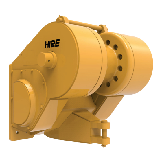
Section 1 General Introduction Description This service manual is for the H12E hydraulic winch. The The H12E Winch is a Power Forward (LINE-IN) and Power following information is included in this manual: Reverse (LINE-OUT) winch. The winch is powered by an internal hydraulic motor connected to the tractor hydraulic Section 1. -
Page 10: Unit Identifi Cation
D85-15 PR754 PR756 RL56 D8R Series II D155AX-6/-7 SD32DQ D275AX-5 D8T Tier 4 1050K Figure 1-2 Tractor Identifi cation Codes and Available Gear Ratios for H12E Winch 1 - 2... -
Page 11: Serial Number Codes
Section 1 Serial Number Codes ALLIED SYSTEMS COMPANY The serial number codes are described on page 1-2 of 21433 SW OREGON STREET this manual. The nameplate with the serial number code SHERWOOD, OREGON 97140 USA WWW.ALLIEDSYSTEMS.COM is found on the top left hand side of the winch case. The... -
Page 12: Specifi Cations
Other hydraulic oils meeting this specifi cation are: ExxonMobil, Mobiltrans HD-30 Chevron, Chevron Drive Train Fluid HD SAE 30. Oil Capacity The oil capacity for H12E winch is approximately 7 gallons (26.5 liters). 1 - 4... -
Page 13: Maintenance Decal
Section 1 Maintenance Decal Figure 1-5 Maintenance Decal Torque Specifi cations TORQUE VALUES (Lubed) ITEM ft-lbs. kg-m Solenoid Cartridge 12-15 16-20 Control Solenoid Cartridge Retaining Nut 1.4-2.7 0.45-0.9 Manifold Control Manifold to Bracket 12.7 Planetary Reducer to Clutch Housing 14.9 Primary Disc to Spring Plate 15-18 20.3-24.4... -
Page 14: Gear Train
General Gear Train (See Fig. 1-8) DRUM GEAR A tractor mounted pump provides hydraulic fl ow to drive the winch motor. The fl ow is controlled in the winch by the hydraulic counterbalance relief manifold and a control INTERMEDIATE GEAR manifold. -
Page 15: Operation And Control
Section 1 Operation & Control BRAKE-OFF is used when there is a load attached to the winch wire rope and the operator wants to move the tractor away from the load with wire rope spooling off the drum in There are two types of internal operation option codes: a controlled manner. -
Page 16: Hydraulic System
General Hydraulic System CBR MANIFOLD (COUNTERBALANCE RELIEF) CONTROL MANIFOLD BRAKE-OFF CLUTCH HYDRAULIC GEAR, MOTOR SPIDER CLUTCH BRAKE PLANETARY REDUCER BRAKE-OFF CLUTCH CONTROL MANIFOLD CBR MANIFOLD (COUNTERBALANCE HYDRAULIC RELIEF) MOTOR PLANETARY REDUCER BRAKE Figure 1-11 Major Components 1 - 8... -
Page 17: Motor
Section 1 51V Series Motor H1B Series Motor Last used on SN H12E***1085*** First used on SN H12E***1086*** Case Drain M5 Port Motor A Port Motor Motor B Port A Port Motor B Port Minimum Displacement Adjustment Pressure Compensator Override (PCOR) Valve... -
Page 18: Brake
General Retaining Ring Retaining Ring Bearing Oil Seal Cover Plate Spline Shaft Assembly Socket Head Shoulder Bolts Primary Disc Rotor Disc Stator Disc Case Gasket Capscrew Dowel Pin Spring Plate Springs Piston Back-Up Ring O-Ring Back-Up Ring O-Ring Bearing Pressure Plate Socket Head Screw Figure 1-13 Brake Brake (See Fig. -
Page 19: Planetary Reducer
Section 1 Sun Gear Thrust Washer Primary Carrier Assembly Fitting Secondary Carrier Assembly Fitting Ring Gear Fitting Cover Label Figure 1-14 Planetary Reducer Planetary Reducer (See Fig. 1-14) A two-stage planetary reducer is the fi rst gear reduction Output shaft rotation is the same as input shaft rotation between the brake and the gear side of the winch. -
Page 20: Counterbalance Relief Manifold
General Port A1 Port B Relief Valve Port ACCUM B Port TS Counterbalance Valve Port B Port ACCUM A Port A1 Relief Valve Port B Port A Figure 1-15 Counterbalance Relief Manifold Counterbalance Relief Manifold (See Fig. 1-15) counterbalance valve allows oil to free fl ow in the LINE- The counterbalance relief (CBR) manifold houses the IN mode through a check valve. -
Page 21: Control Manifold
Section 1 Brake Valve Port PP Port PD Port FS Port Brake Port BO Port TP-BRAKE Solenoid Valves Port RO Port RI Port X1 Figure 1-16 Control Manifold Control Manifold (See Fig. 1-16) pilot pressure to release the brake. One solenoid valve is The control manifold contains the brake valve, two used to send pilot pressure to release the BRAKE-OFF solenoid valves and a shuttle valve to direct pilot pressure... - Page 22 General Tractor Control Lever Control Center Position Lever Pilot Operated To Tractor Drain To Tractor Pilot Ripper Supply Valve From Tractor Control Manifold Counterbalance Relief Manifold Brake-Off Clutch Planetary Reducer Brake High Pressure High Pressure Motor Low Pressure Low Pressure Note: Electrical Control Wiring between the Brake-Off control Pilot Pressure...
- Page 23 Section 1 Sequence of Operation - BRAKE-ON, Option Code B With control lever centered, the tractor ripper valve blocks Pilot pressure is present at the control manifold. All control fl ow to the winch. lines are open to tank. The spring-applied holding brake locks the motor shaft from rotating.
-
Page 24: Line-In
General Control Lever LINE IN Position Tractor Control Lever Pilot Operated To Tractor Drain To Tractor Pilot Ripper Supply Valve From Tractor Control Manifold Counterbalance Relief Manifold Brake-Off Clutch Planetary Reducer Brake High Pressure Motor Low Pressure Note: Electrical Control Wiring between the Brake-Off control Pilot Pressure switch and control manifold is not... - Page 25 Section 1 Sequence of Operation - LINE-IN, Option Code B Pilot pressure at motor X1 port is proportional to control Pulling the control lever toward the operator commands lever position. When the pressure at X1 reaches a preset the tractor ripper valve to send oil fl owing to the winch, level, the motor servo reduces motor displacement through the counterbalance relief manifold and to the motor “A”...
- Page 26 General Tractor Control Lever Pilot Operated Control Lever LINE OUT Position To Tractor Drain To Tractor Pilot Ripper Supply Valve From Tractor Control Manifold Counterbalance Relief Manifold Brake-Off Clutch Planetary Reducer Brake Motor High Pressure Back Pressure Note: Electrical Control Wiring between the Brake-Off control Pilot Pressure switch and control manifold is not...
-
Page 27: Line-Out
Section 1 Sequence of Operation - LINE-OUT, Option Code B In LINE-OUT operation, oil fl owing from motor port “A” LINE-OUT operation is similar to LINE-IN except moving to the counterbalance relief manifold is controlled by the the control lever away from the operator reverses fl ow counterbalance valve. - Page 28 General Tractor Control Lever Control Center Position Lever Pilot Operated To Tractor Drain To Tractor Pilot Ripper Supply Valve From Tractor Control Manifold Counterbalance Relief Manifold Brake-Off Clutch Planetary Reducer Brake High Pressure Motor Low Pressure Note: Electrical Control Wiring between the Brake-Off control Pilot Pressure switch and control manifold is not...
- Page 29 Section 1 Sequence of Operation - BRAKE-OFF, Option Code B BRAKE-OFF is activated by a switch located on the BRAKE-OFF should not be used to lower operator console. An electric signal shifts the BRAKE- a suspended load or a load that can slide OFF solenoid valve directing pilot pressure to release the down a slope.
- Page 30 General Tractor Control Lever Control Center Position Lever Electric Operated To Tractor Drain To Tractor Ripper Valve Pilot Supply From Tractor Control Manifold Counterbalance Relief Manifold Brake-Off Clutch Planetary Reducer Brake Motor High Pressure Note: Electrical control wiring Low Pressure between the Brake-Off and Hi-Speed control switches and Pilot Pressure...
- Page 31 Section 1 Sequence of Operation - BRAKE-ON, Option Code D Pilot pressure is present at the counterbalance relief With control lever centered, the tractor ripper valve blocks manifold. All control lines are open to tank. The spring- fl ow so hot oil is fl owing to the winch counterbalance relief applied holding brake locks the motor shaft from rotating.
- Page 32 General Control Lever LINE IN Position Tractor Control Lever Electric Operated To Tractor Drain To Tractor Ripper Valve Pilot Supply From Tractor Control Manifold Counterbalance Relief Manifold Brake-Off Clutch Planetary Reducer Brake Motor High Pressure Note: Electrical control wiring Low Pressure between the Brake-Off and Hi-Speed control switches and Pilot Pressure...
- Page 33 Section 1 Sequence of Operation - LINE-IN, Option Code D Pulling the control lever toward the operator commands to the control manifold RO port through the shuttle valve, the tractor ripper valve to send oil fl owing to the winch, to the brake valve.
-
Page 34: Brake-Off
General Control Lever LINE IN Position Tractor Control Lever Electric Operated (HI-SPEED switch activated) To Tractor Drain To Tractor Ripper Valve Pilot Supply From Tractor Control Manifold Counterbalance Relief Manifold Brake-Off Clutch Planetary Reducer Brake Motor High Pressure Note: Electrical control wiring Low Pressure between the Brake-Off and Hi-Speed control switches and... -
Page 35: Option Code D
Section 1 Sequence of Operation - LINE-IN HI-SPEED, Option Code D If the operator selects HI-SPEED mode by the rocker displacement to increase line speed. If working pressure switch on the control panel, an electric solenoid valve on increases to PCOR setting, the motor servo begins to the control manifold sends pilot pressure to the X1 port on increase displacement to increase line pull. - Page 36 General Tractor Control Lever Electric Operated Control Lever LINE OUT Position To Tractor Drain To Tractor Ripper Valve Pilot Supply From Tractor Control Manifold Counterbalance Relief Manifold Brake-Off Clutch Planetary Reducer Brake Motor High Pressure Note: Electrical control wiring Back Pressure between the Brake-Off and Hi-Speed control switches and Pilot Pressure...
- Page 37 Section 1 Sequence of Operation - LINE-OUT, Option Code D to the counterbalance relief manifold is controlled by the LINE-OUT operation is similar to LINE-IN except moving counterbalance valve. The counterbalance valve maintains the control lever away from the operator reverses fl ow suffi...
- Page 38 General (BRAKE OFF switch activated) Tractor Control Lever Control Center Position Lever Electric Operated To Tractor Drain To Tractor Ripper Valve Pilot Supply From Tractor Control Manifold Counterbalance Relief Manifold Brake-Off Clutch Planetary Reducer Brake Motor High Pressure Note: Electrical control wiring Low Pressure between the Brake-Off and Hi-Speed control switches and...
- Page 39 Section 1 Sequence of Operation - BRAKE-OFF, Option Code D BRAKE-OFF is activated by a switch located on the BRAKE-OFF should not be used to lower operator console. An electric signal shifts the BRAKE- a suspended load or a load that can slide OFF solenoid valve, directing pilot pressure to release down a slope.
- Page 40 General FRONT Brake-On Pilot Drain Pilot Supply ACCUM B Counterbalance BRAKE Relief Manifold Control Manifold Drain Pressure Pilot Pressure Figure 1-26 Sequence of Operation - BRAKE-ON, Komatsu D155AX-6/-7 (K64) 1 - 32...
- Page 41 Section 1 Sequence of Operation - BRAKE-ON (K64) Pilot pressure is present at the control manifold. All control With control lever centered, the tractor ripper valve blocks lines are open to tank. The spring-applied holding brake fl ow to the winch. locks the motor shaft from rotating.
- Page 42 General FRONT Line-In From Pilot Dozer Dozer Drain Ripper Ripper Valve Valve Pilot Supply ACCUM B Counterbalance BRAKE Relief Manifold Control Manifold Energized During Hi-Speed High Pressure Low Pressure Drain Pressure Pilot Pressure Figure 1-27 Sequence of Operation - LINE-IN, Komatsu D155AX-6/-7 (K64) 1 - 34...
- Page 43 Section 1 Sequence of Operation - LINE-IN HI-SPEED (K64) Pulling the control lever toward the operator commands If the operator selects HI-SPEED mode by the rocker the tractor ripper valve to send oil fl owing to the winch, switch on the control panel, an electric solenoid valve on through the counterbalance relief manifold to the motor “A”...
-
Page 44: Line-Out
General FRONT Line-Out From Pilot Dozer Dozer Drain Ripper Ripper Valve Valve Pilot Supply ACCUM B Counterbalance BRAKE Relief Manifold Control Manifold Energized During Hi-Speed High Pressure Low Pressure Back Pressure Drain Pressure Pilot Pressure Figure 1-28 Sequence of Operation - LINE-OUT, Komatsu D155AX-6/-7 (K64) 1 - 36... - Page 45 Section 1 Sequence of Operation - LINE-OUT HI-SPEED (K64) In LINE-OUT operation, oil fl owing from motor port “A” LINE-OUT operation is similar to LINE-IN except moving to the counterbalance relief manifold is controlled by the the control lever away from the operator reverses fl ow counterbalance valve.
-
Page 46: Brake-Off
General FRONT Brake-Off Pilot Drain Pilot Supply ACCUM B Counterbalance BRAKE Relief Manifold Control Manifold Drain Pressure Pilot Pressure Figure 1-29 Sequence of Operation - BRAKE-OFF, Komatsu D155AX-6/-7 (K64) 1 - 38... - Page 47 Section 1 Sequence of Operation - BRAKE-OFF, HI-SPEED (K64) BRAKE-OFF is activated by a switch located on the BRAKE-OFF should not be used to lower operator console. An electric signal shifts the BRAKE- a suspended load or a load that can slide OFF solenoid valve, directing pilot pressure to release down a slope.
- Page 48 General Notes 1 - 40...
- Page 49 Section 1 Figure 1-30 H12E Hydraulic/Electrical Schematic, Option Code B - Komatsu D275AX-5 (K65) 1 - 41...
- Page 50 Section 1 Figure 1-31 H12E Hydraulic/Electrical Schematic, Option Code D - Komatsu D155AX-6/7 (K64) Last Used on SN 1044 1 - 42...
- Page 51 Section 1 Figure 1-32 H12E Hydraulic/Electrical Schematic, Option Code D - Komatsu D155AX-7/8 (K64) First Used on SN 1045 1 - 43...
- Page 52 Section 1 Figure 1-33 H12E Hydraulic/Electrical Schematic, Option Code B - Komatsu D85-15 (K50) 1 - 44...
- Page 53 Section 1 Figure 1-34 H12E Hydraulic/Electrical Schematic, Option Code B - Liebherr PR754 (L54) 1 - 45...
- Page 54 Section 1 Figure 1-35 H12E Hydraulic/Electrical Schematic, Option Code B - CAT D8T (C74) 1 - 46...
- Page 55 Section 1 Figure 1-36 H12E Hydraulic/Electrical Schematic, Option Code D - CAT D8T (C74) 1 - 47...
- Page 56 Section 1 Figure 1-37 H12E Hydraulic/Electrical Schematic, Option Code B - John Deere JD-1050K (E75) 1 - 48...
- Page 57 Section 1 Figure 1-38 H12E Hydraulic/Electrical Schematic, Option Code D - John Deere JD-1050K (E75) 1 - 49...
- Page 58 Section 1 Figure 1-39 H12E Hydraulic/Electrical Schematic, Option Code D - Shantui SD32DQ (U64) 1 - 50...
- Page 59 Section 1 Figure 1-40 H12E Hydraulic/Electrical Schematic, Option Code D - CAT D8R (C59) 1 - 51...
-
Page 60: Troubleshooting
Section 2 Troubleshooting General Mechanical/Hydraulic Troubleshooting Winch problems fall into one of three categories: control For proper hydraulic troubleshooting, the winch oil oper- system, hydraulic system or mechanical system. Follow ating temperature should not exceed 180°F (82°C). Oil the troubleshooting steps below to isolate the problem reservoir temperature is monitored at the dozer. - Page 61 Troubleshooting PROBLEM POSSIBLE CAUSE CORRECTION ACTION Winch Operates But Exhibits The Following Problems Winch operates in LINE-IN only. Brake shuttle stuck. Check for debris. Counterbalance valve pilot signal Check for plugged control manifold blocked or connected to drain. passage or missing manifold plug. Counterbalance valve damaged or Adjust or replace counterbalance set incorrectly.
- Page 62 Winch stalls during operation. Incorrect PCOR setting on hydraulic Check PCOR and dozer supply motor. pressures (see Section 3). If either is incorrect, contact Allied Service Insuffi cient hydraulic pressure Department. supplied by dozer. Figure 2-1 Mechanical/Hydraulic Troubleshooting Chart - 3...
- Page 63 Troubleshooting Notes 2 - 4...
-
Page 64: Service
Access Cover for Motor and Winch Hydraulics Oil Fill Plug Oil Level Check Plug Breather Oil Drain Plug Figure 3-1 H12E Winch Maintenance Points INTERVAL PROCEDURE OR QUANTITY SPECIFICATION 50 hours or weekly Check oil level at plug (item 2). Add oil as See Oil Specifi... - Page 65 Service Cross Port Relief Valve Cross Port Relief Valve Figure 3-2 Hydraulic Pressure Test Ports (some items removed for clarity) 3 - 2...
-
Page 66: Maintenance Schedule
Section 3 Brake Test Port (TP-BRAKE or TP-BR) Brake-Off Test Port (BO) Motor B Test Port Motor A Test Port Figure 3-3 Hydraulic Pressure Test Ports (Installation on Komatsu D155AX-8 (K64) Shown Checks Before Operation Check that the wire rope and hook are not worn or Dozer engine must be shut OFF before damaged beyond serviceable condition. -
Page 67: Pilot Supply Pressure Check
Service Pilot Supply Pressure Check All except installation on SD32DQ (U64) Instructions 1000 PSI Gauge 1. Shut engine off but turn dozer key switch back on to at Dozer Pilot provide electrical power to the winch. Test Port 2. Move dozer work equipment lever to unlock position to enable winch. -
Page 68: Motor Supply Pressure Check
Section 3 Motor Supply Pressure Check If the motor supply pressure is not as specifi ed in Table 3-3, check for: 1. If pressure is too high, check dozer hydraulic system. 2. If it is too low, proceed with troubleshooting to identify other possible problems, including a possibly damaged motor or pump. -
Page 69: Brake Pressure Check
Service Brake Pressure Check Instructions 1. With the engine shut off, connect a 1000 psi pressure gauge to the TP-BRAKE (or TP-BR) pressure test port on the control manifold. 2. Start dozer and set to high-free idle 3. Operate the winch in LINE-IN and LINE-OUT. 4. -
Page 70: Brake-Off Pressure Check
Section 3 BRAKE-OFF Pressure Check Instructions 1. With the engine shut off, connect a 1000 psi pressure gauge to the BO pressure test port. 2. Start dozer and set to high-free idle 3. Measure pressure with the BRAKE-OFF switch activated. 4. -
Page 71: Brake Valve Pressure Check & Adjustment
Service Brake Valve Pressure Check and Adjustment All except installations with 2 speed control Brake Valve Adjustment 1. Slowly meter the control lever into the LINE-IN position. 2. Measure pressure at TP-BRAKE and XI pressure test ports. 3. Loosen brake valve locknut. Turn adjusting capscrew OUT to decrease pressure and IN to increase pressure. -
Page 72: Line-In Pressure Check
Section 3 LINE-IN Pressure Check All except installation on D155AX-6/-7 (K64), D8R Series II (C59), SD32DQ (U64) Instructions 1. With the engine shut off, connect a 1000 psi pressure gauge in line on the RI hose at the control manifold. 2. -
Page 73: Line-Out Pressure Check
Service LINE-OUT Pressure Check All except installation on D155AX-6/-7 (K64), D8R Series II (C59), SD32DQ (U64) Instructions 1. With the engine shut off, connect a 1000 psi pressure gauge in line on the RO hose at the control manifold. 2. Start dozer and set to high-free idle. 3. -
Page 74: Pcor Pressure Check
M5 is the PCOR setting. Figure 3-11 Test Equipment Setup 12. Check Table 3-7 below. If the PCOR setting is not within tolerance, or if the pressure read at M5 doesn’t stabilize as described above, contact Allied Systems Test Equipment: Service Department. •... - Page 75 Notes Service 3 - 12...
-
Page 76: Repairs
Section 4 Repairs General Winch Removal 1. Remove the wire rope from the drum. Clean the This section includes the removal and disassembly of outside of the winch and the area where the winch all major assemblies, inspection of components, and contacts the tractor. -
Page 77: Intermediate Shaft Removal
Repairs - Intermediate Shaft Removal Intermediate Shaft Removal The intermediate shaft can be removed with the winch mounted on the tractor. Winch is shown on its side in these illustrations. 1. Shim .005 2. Shim .007 3. Shim .020 4. Intermediate Shaft Cover 5. - Page 78 Section 4 1. Remove the intermediate shaft cover. 5. Remove the intermediate shaft, while ensuring that the intermediate gear does not fall. 2. Remove shims and tag them for reference during reassembly. NOTE: If the shaft or bearing are replaced, the shim height may change.
-
Page 79: Drum Shaft & Drum Removal
Repairs - Drum Shaft & Drum Removal Drum Shaft and Drum Removal Figure 4-2 shows the location of drum and drum shaft D o n o t a t t e m p t t o r e m ov e h e av y components. - Page 80 Section 4 Loosen the drum capscrews, then remove capscrews Remove bearing retainer and shim pack. with thimbles, leaving two located 180° apart. NOTE: Tag shim pack for reference during reassembly. Remove drum shaft locknuts. Remove retainer plate by removing retainer capscrews and washers.
- Page 81 Repairs - Drum Shaft & Drum Removal Remove roller bearing. Remove two remaining drum capscrews mentioned in Step 1. NOTE: Bearing, cups and spacers are a matched set, and must not be interchanged with other bearing set Carefully remove the drum from winch frame. Ensure components.
- Page 82 NOTE: Bearing, cups and spacers are a matched set, and must not be interchanged with other bearing set components. NOTE: This seal must be replaced with a new Allied Systems Company-approved seal during reassembly. NOTE: Refer to Figure 4-2 on page 4-5 for location of components.
-
Page 83: Hydraulic System Disassembly
Repairs - Hydraulic System Disassembly Hydraulic System Disassembly Disconnecting the hoses is necessary in order to remove sure to clearly mark the hose ends of any hoses removed the motor shaft assembly. For easier re-installation, be with their corresponding ports. NOTE: SOME COMPONENTS ARE NOT SHOWN FOR CLARITY. - Page 84 Section 4 Drain oil from winch, and remove covers as shown. Remove the control manifold assembly. Remove the hoses and tube assemblies shown L o o s e n t h e c a p s c r ew s, a n d r e m ove t h e below.
-
Page 85: Motor Shaft Removal & Disassembly
Repairs - Motor Shaft Removal & Disassembly Motor Shaft Removal and Disassembly Removal and disassembly of certain motor shaft planetary reducer and clutch housing requires removing the Intermediate Shaft and Gear fi rst (see Intermediate components can be accomplished while the winch is Shaft Removal section). - Page 86 Section 4 Remove the motor support from winch frame. Remove the manifold bracket plate and brake. Remove Studs if damaged. Manifold Bracket Plate Brake Studs Remove the hydraulic motor. Remove the bearing cover, shims and the bearing. NOTE: Tag shim pack for reference during reassembly. 4 - 11...
- Page 87 Repairs - Motor Shaft Removal & Disassembly Remove planetary reducer/clutch housing assembly. Remove the RH cover. Remove and discard the O-ring. Remove any fi ttings that would prevent the reducer/ clutch housing assembly from being removed. Remove the clutch housing from the reducer. 4 - 12...
- Page 88 Section 4 12. Pull the clutch assembly from clutch housing. 10. Remove spider gear, shims, bearings and spacer. Clutch Housing Shim Spring Dowel Pin Ring, Snap Spider Gear Shims Bearings Retaining Clutch Ring Assembly 11. Remove 6mm socket head capscrew. Drive seal ring 13.
-
Page 89: Brake-Off Clutch Disassembly
NOTE: Disassembling the clutch while it’s still under its warranty period immediately invalidates the warranty. If the clutch malfunctions before its warranty period expires, please contact Allied Systems Company fi rst before attempting to repair it. BRAKE-OFF Clutch is under pressure. - Page 90 Section 4 Intentionally Blank 4 - 15...
-
Page 91: Brake Disassembly
Repairs - Brake Disassembly Brake Disassembly expires, please contact Allied Systems Company fi rst NOTE: Disassembling the brake while it’s still under its before attempting to repair it. warranty period immediately invalidates the warranty. If the brake malfunctions before its warranty period... - Page 92 Section 4 Remove the four socket head screws (item 23). A NOTE: suitable holding fi xture is useful to keep brake in position. 1. Primary disc is positioned by shoulder bolts (item 7) and stator discs are positioned on dowel Tap female end of spline shaft assembly (item 6) and pins (item 13).
-
Page 93: Planetary Reducer Disassembly
- Planetary Reducer Disassembly Planetary Reducer Disassembly NOTE: Disassembling the reducer while it’s still its warranty period expires, please contact Allied under its warranty period immediately invalidates Systems Company fi rst before attempting to repair it. the warranty. If the reducer malfunctions before... - Page 94 Section 4 Remove capscrews and washers (not shown) Remove primary carrier assembly (item 2) and from cover (item 5). Thrust washer (item 6) usually secondary carrier assembly (item 3) from ring gear remains with cover (item 5). (item 4). Lift sun gear (item 1) from primary carrier assembly Remove fi...
-
Page 95: Winch Assembly
Repairs - Winch Assembly Winch Assembly All components should be inspected for wear or damage that indicates excessive wear or damage should be as they are removed. Refer to Figure 4-7, Visual Inspection. replaced. The following reassembly and installation All seals that were removed should be replaced during sequence assumes a complete winch overhaul. - Page 96 Section 4 ITEM INSPECTION REQUIREMENTS CORRECTIVE ACTION Intermediate Shaft Check for deep scratches or scoring on Dress surface or replace shaft if severely worn. bearing surfaces at each end of shaft. Check for broken or severely worn splines. Replace if splines are broken or severely worn. Intermediate Gears Inspect both gears for broken or severely Replace gears if teeth are broken or severely worn.
-
Page 97: Brake Assembly
Repairs - Brake Assembly Brake Assembly expires, please contact Allied Systems Company fi rst NOTE: Disassembling the brake while it’s still under its before attempting to repair it. warranty period immediately invalidates the warranty. If the brake malfunctions before its warranty period... - Page 98 Section 4 NOTE: Lubricate all rubber components with clean 10. Install springs (item 15) according to pattern and hydraulic fl uid before reassembly. color recorded during disassembly. Clean all parts thoroughly before assembling. 11. Affi x case gaskets (item 11) to pressure plate (item 22) and spring plate (item 14).
-
Page 99: Brake-Off Clutch Assembly
If the clutch malfunctions before its warranty period Advance retainer three additional teeth & align with expires, please contact Allied Systems Company fi rst hub splines. before attempting to repair it. Draw a line across adjacent teeth with marker. - Page 100 Section 4 Remove retainer noting the number of turns required 13. Install retainer to height “D”. (use the number of turns for removal. required for removal & align marks on teeth). 10. Disassemble clutch. 14. Install frictions, separators, & clutch plate. 11.
- Page 101 Repairs - BRAKE-OFF Clutch Assembly 16. Install 1.75” (45mm) long or longer M10 x 1.5 22. Alternately loosen the three longer capscrews & capscrews into holes with pins. (Longer, fully remove them but leave the pins in place. threaded capscrews work better). 23.
- Page 102 Section 4 Intentionally Blank 4 - 27...
-
Page 103: Motor Shaft Assembly & Installation
Repairs - Motor Shaft Assembly & Installation Motor Shaft Assembly and Installation Assembly and installation of the motor shaft assembly can but the planetary reducer and reducer housing must be be accomplished while the winch is mounted on the tractor. installed before the Intermediate Shaft and Gear (see The motor and brake can be installed independently of Intermediate Shaft Installation section). - Page 104 Section 4 Install new O-rings on seal ring and clutch piston, Lower clutch assembly vertically using jib hoist and then install thrust needle roller bearing, thrust ring, M12x1.75 metric eyebolt. and snap ring. Align paint marks on piston and clutch housing. Assembly, Clutch Position seal ring so three locking tabs align with Shaft, Clutch...
- Page 105 Repairs - Motor Shaft Assembly & Installation While clutch is released, friction disks can be aligned Rotate seal ring clockwise with brass drift and by carefully assembling spider gear and aligning hammer until lock bolt notch aligns with bolt hole. splines.
-
Page 106: Planetary Reducer Assembly
If the reducer malfunctions before its BRAKE-OFF Pressure Port Clutch Housing warranty period expires, please contact Allied Systems Assembly Allied Systems Lable Company fi rst before attempting to repair it. Fill Port Fitting... - Page 107 Repairs - Motor Shaft Assembly & Installation 13. Apply bead of anaerobic sealant (e.g., Loctite 515) to 15.3 Torque 3/4” hardware to 280 ft-lbs (380 N-m). Torque the RH cover plate. Reinstall RH cover plate. Torque M12 hardware to 66 ft-lbs (90 N-m). capscrews to 165 ft-lbs (225 N-m).
- Page 108 Section 4 Intentionally Blank 4 - 33...
-
Page 109: Hydraulic System Assembly
Repairs - Hydraulic System Assembly Hydraulic System Assembly (BRAKE-OFF CLUTCH TO BO PORT ON CONTROL MANIFOLD) 1, 2, 3 (PD TO MOTOR CASE) (PD) (MOTOR A) (BRAKE) (MOTOR B) 14, 20 (X1 TEST PORT) (PP) 2, 3 (X1 TO MOTOR X1) 13, 14 (MOTOR X1) (MOTOR TEST PORT "B"... - Page 110 Section 4 Install the counterbalance relief (CBR) manifold on Reinstall hose and tube assemblies. Alternately the mounting bracket. Leave mounting bolts loose. tighten connections to prevent placing motor tubes in a bind. Adjust mounting bracket as necessary to align with manifold. Install the control manifold.
-
Page 111: Drum & Drum Shaft Installation
Repairs - Drum & Drum Shaft Installation Drum and Drum Shaft Installation If the drum gear was removed, it must be installed prior to installation of the intermediate shaft and motor shaft assembly. Capscrew Keeper Gear, Drum Washer Capscrew Drum O-Ring Washer Spacer... - Page 112 Section 4 Install double-lip oil seal with smooth side toward the Replace drum spacer O-ring and install spacer in drum in the right hand side of the frame. drum bore. Install drum oil seal. NOTE: Smooth side of seal must face outboard. Install drum adapter by pushing it through the double- Lubricate right-hand drum bore.
- Page 113 Repairs - Drum & Drum Shaft Installation Move the drum into position while being careful not Install drum gear. to move the oil seal or O-ring. Align adapter and drum holes, then install the Align drum gear with adapter and temporarily secure thimbles and screws.
- Page 114 Section 4 Make sure that double-tapered roller bearing, seal 11. Reinstall retainer plate using the eight special and spacer are properly seated in the left-hand side capscrews. Tighten capscrews to 180 ft-lbs (244 of the drum. Then install the shaft until it bottoms N-m).
- Page 115 Repairs - Drum & Drum Shaft Installation 14. Secure retainer with capscrews and lockwashers. 16. Tighten drum-to-adapter capscrews to 180 ft-lbs (244 Tighten capscrews to 165 ft-lbs (225 N-m). N-m) torque. 15. Coat shaft nut threads with anti-seize. Apply RTV sealant (e.g., Loctite 593 RTV) between the left drum nut and frame, and between the right drum nut and drum retainer.
- Page 116 Section 4 Intentionally Blank 4 - 41...
-
Page 117: Intermediate Shaft Installation
Repairs - Intermediate Shaft Installation Intermediate Shaft Installation 1. Shim .005 2. Shim .007 3. Shim .020 4. Intermediate Shaft Cover 5. Roller Bearing Cone 6. Roller Bearing Cup 7. Intermediate Gear 8. Drum Pinion Gear 9. Intermediate Shaft 10. Washer 11. - Page 118 Section 4 Install inner bearing assembly if previously removed. Install the outer bearing cup and cone. Make sure Install drum pinion gear. Use a liberal amount of that the cup is fi rmly seated against the bearing cone. lubriplate or other light lube grease to hold the inner bearing cone in place.
- Page 119 Repairs Notes 4 - 44...
- Page 121 To fi nd a dealer in your area, Call: (503) 625-2560, Fax: (503) 625-7269 , or Email: marketing@alliedsystems.com, or Visit our website: http://www.alliedsystems.com 599049W 4/7/2020 Printed in U.S.A.
Need help?
Do you have a question about the H12E and is the answer not in the manual?
Questions and answers