Table of Contents
Advertisement
Quick Links
OPERATOR'S MANUAL
CONTROLLER OPERATION
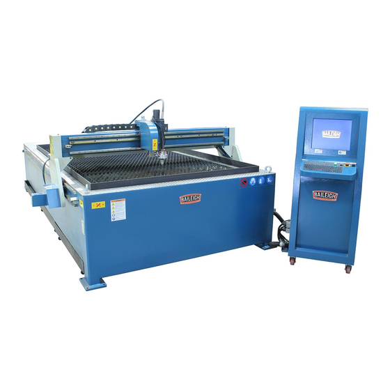
MODEL: PT-105HD-W
Baileigh Industrial
1625 Dufek Drive
Manitowoc, WI 54220
Phone: 920.684.4990
Fax: 920.684.3944
sales@baileigh.com
REPRODUCTION OF THIS MANUAL IN ANY FORM WITHOUT WRITTEN APPROVAL OF BAILEIGH INDUSTRIAL IS
PROHIBITED. Baileigh Industrial does not assume and hereby disclaims any liability for any damage or loss caused
by an omission or error in this Operator's Manual, resulting from accident, negligence, or other occurrence.
Edition 1 01/2022
Advertisement
Table of Contents

Summary of Contents for Baileigh Industrial PT-105HD-W
- Page 1 REPRODUCTION OF THIS MANUAL IN ANY FORM WITHOUT WRITTEN APPROVAL OF BAILEIGH INDUSTRIAL IS PROHIBITED. Baileigh Industrial does not assume and hereby disclaims any liability for any damage or loss caused by an omission or error in this Operator’s Manual, resulting from accident, negligence, or other occurrence.
-
Page 2: Table Of Contents
Table of Contents INTRODUCTION ......................1 GENERAL NOTES ......................1 SAFETY INSTRUCTIONS ....................2 SAFETY PRECAUTIONS ....................5 Dear Valued Customer: ....................5 TECHNICAL INFORMATION AND SUPPORT ............... 7 Read This Manual ....................... 7 Work Condition ......................7 Maintenance ........................ 7 High Voltages ...................... - Page 3 Breakpoint Recovery ....................30 FILE OPERATION ......................31 Files in the Hard Disk ....................31 Files in the U Disk ...................... 31 Search File ........................ 32 Edit Code ........................32 New Code ........................32 Compile Code ......................32 PARAMETER SETTING ....................33 Common Parameters ....................
-
Page 4: Introduction
INTRODUCTION The quality and reliability of the components assembled on a Baileigh Industrial machine guarantee near perfect functioning, free from problems, even under the most demanding working conditions. However, if a situation arises, refer to the manual first. If a solution cannot be found, contact the distributor where you purchased our product. -
Page 5: Safety Instructions
IMPORTANT PLEASE READ THIS OPERATORS MANUAL CAREFULLY It contains important safety information, instructions, and necessary operating procedures. The continual observance of these procedures will help increase your production and extend the life of the equipment. SAFETY INSTRUCTIONS LEARN TO RECOGNIZE SAFETY INFORMATION This is the safety alert symbol. - Page 6 SAVE THESE INSTRUCTIONS. Refer to them often and use them to instruct others. PROTECT EYES Wear safety glasses or suitable eye protection when working on or around machinery. PROTECT SKIN Keep hands and body protected from the plasma arc and hot sparks. The heat from the plasma arc is very intense and can pierce the skin resulting in serious burns.
- Page 7 CUTTING SPARKS A spark or piece of hot metal can fly out of the arc while cutting. Remove all flammable materials from the plasma cutting area. Wear approved eye protection, and proper hand and body protection. Make sure the cutting tip is not grounded when sitting idle, which could cause heat buildup, resulting in a possible fire.
-
Page 8: Safety Precautions
Baileigh Industrial does not recommend or endorse making any modifications or alterations to a Baileigh Industrial machine. Modifications or alterations to a machine may pose a substantial risk of injury to the operator or others and may do substantial damage to the machine. - Page 9 8. Use the right tool for the job. DO NOT attempt to force a small tool or attachment to do the work of a large industrial tool. DO NOT use a tool for a purpose for which it was not intended. 9.
-
Page 10: Technical Information And Support
26. Keep all cords dry, free from grease and oil, and protected from sparks and hot metal. 27. DO NOT bypass or defeat any safety interlock systems. 28. Learn the function and controls of the controller, the automatic height control, the torch power supply, and the provided software packages. -
Page 11: Technical Support Contact
Technical Support Contact Our technical support department can be reached at 920.684.4990 and asking for the support desk for purchased machines. Tech Support handles questions on machine setup, schematics, warranty issues, and individual parts needs: (other than die sets and blades). For specific application needs or future machine purchases contact the Sales Department at: sales@baileigh.com, Phone: 920.684.4990, or Fax: 920.684.3944. -
Page 12: Introduction
INTRODUCTION The F2500T digital controller can control the motion of two axes, which is apt to the application of plasma cutting. The controller provides menu / illustration for each operation which provides convenient operation. The controller uses high speed DSP and ARM as its core to assure the cutting process to be stable. -
Page 13: Technical Standard
• According to plate thickness, the cutting speed is automatically restricted by a speed limit in the corner, effectively preventing over burn. • Select row and column manually. • Dynamic/static illustration of the process, graphics zoom in / out, dynamically tracking cut-off point under zooming state. -
Page 14: System Board And Main Interface
SYSTEM BOARD AND MAIN INTERFACE Operating Board Introduction [F1] – [F10]: Function key in different interfaces. [S↑/PgUP]: Page-up key of code interface or Torch up in other interfaces. [S↓/PgDn]: Page-down key of code interface or Torch down in other interfaces. [F+/HOME]: Accelerate or skip to the head of the code line. -
Page 15: Power On Process And Main Interface
Power On Process and Main Interface When powered on, the system will go for the process of self-scan. In the starting process, there are 3 seconds to countdown, before the countdown is over, if pressing [F2], it will enter the bios starting interface (please take the reference of the appendix 2 to run bios). - Page 16 In the main interface, press [F1] – [F8] for the following functions: [F1]: ShapeLib: Pressing F1 to enter the Shape Library including 45 common shapes, and most of them have plate size and hole size. [F2]: Files: You can load local files, U disk files or edit, import, export and delete codes. [F3]: PartOption: Accesses actions of mirroring, rotation, plate adjusting, plate arraying, selecting row and hole or code edition etc.
-
Page 17: Function Index Of Main Interface
Function index of main interface... -
Page 18: Cutting Function
CUTTING FUNCTION In the main interface, press the [SPACE] to enter the cutting interface, shown as follows: Show the current workpiece’s cutting path, including the slotted value. Show the G-code being processed, shows the current and next line. Show the current cutting speed, during processing, you can press the keyboard's number keys [1] –... -
Page 19: Speed Control And Adjustment
• Press [G]: Modify the current fixed-length fixed long-distance move. • [START ([F9]): Start cutting. • [STOP ([F10]): Parking, the system can suspend all on-going actions. Cutting Operation Index • [F1]: The torch moves back along the cutting path. • [F2]: The torch moves forward along the cutting path. •... -
Page 20: Forward
In the cutting interface, on the operation panel, press the number keys [1] – [9], the speed will quickly adjust to the corresponding percentage of the key pressed times 10. For example, press [3], adjust to 30% of the speed limit you have set, press [8], adjust to 80% of the speed limit you have set. -
Page 21: Edge Cutting / Offset Cutting / Return
Edge Cutting / Offset Cutting / Return When the torch is not on the actual path of the current workpiece, the system will prompt the operator to identify which action should happen next. There are two ways in which this situation will occur. 1. -
Page 22: Perforation Point Selection
During the return process, the [F10] “Stop” button can be pressed if needed to stop the operation. When the reason for the stoppage is cleared, press the [F3] key to restart the return to refence operation. Perforation Point Selection Before you start cutting or when cutting is paused, the function key prompt [F8] will display "select new pierce". -
Page 23: Frame Function
Frame Function The “Frame” function will move the torch on the table to draw a box around the part to be cut. This box will represent the maximum boundaries that the part will require during the cut. In short, this will allow the operator to see if the part will fit on the material to be cut out of. -
Page 24: Part Options
PART OPTIONS Before starting to cut, you can use the “F3 Part Option” in the main interface. Press F3 to enter the part options menu. [F1] Mirror Press F1, the system will prompt: X mirror Y mirror • Press F1 to mirror along the horizontal axis (X axis) -
Page 25: Angle Adjustment
• Press F2 to mirror along the vertical axis (Y axis) • Press ESC to exit mirror operation Angle Adjustment Press F2, the system will prompt: Steel-plate adjust Enter angle • Press F1 to adjust steel plate • Press F2 to enter angle directly •... -
Page 26: Array
After adjusting, the system will ask whether to return to the start point. If pressing [ENTER], the system will move back to the start point of the operation. If pressing [ESC], the system will do nothing but go back to the graphic interface. Enter angle When the angle of the current workpiece is known, you can enter the angle. - Page 27 Matrix Press [F1] to carry on arranging in matrix. Enter the information for the number Rows, Columns, and Row and Column spacing and then press [F8]. The result shows the number of rows and columns entered. If the spacing is too large or too small, then the parts will either have large gaps between the parts or they will display as overlapping each other.
- Page 28 Staggered Press [F2] to enter staggered arrangement. Enter the information for the number of Rows, Columns, and Row and Column spacing and then press [F8]. The result shows the number of rows and columns entered. If the spacing is too large or too small, then the parts will either have large gaps between the parts or they will display as overlapping each other.
- Page 29 Stacked Press [F3] to enter the stacked arrangement. Enter the information for the number of Rows, Columns, and Row and Column spacing and then press [F8]. The result shows the number of rows and columns entered. If the spacing is too large or too small, then the parts will either have large gaps between the parts or they will display as overlapping each other.
-
Page 30: Zoom In/Out
Zoom in/out In the part options menu, press [F4] (zoom in/out), the system will prompt to enter a proportion number. Example; 0.8 = reduce to 80% 1.2 = increase to 120% After entering the scale, press [Enter], the system will automatically zoom in or zoom out the graphic when the parameter is checked to be correct. -
Page 31: Operation After Select Row/Number
Operation after select row/number After selecting the row or number, press [F8] continuously to exit to the main interface. Press the SPACE button to enter the cutting interface. There are two kinds of operation: 1. Move from current position to the new position and then start cutting. •... -
Page 32: Manual Function
MANUAL FUNCTION In the automatic interface, press [F7] (Manual) to enter the manual function interface. The speed in the manual status is controlled by the manual moving parameters. During the process of fixed moving function, you can adjust the speed by the acceleration or deceleration key. -
Page 33: Continuous Moving Function
Continuous Moving Function When in the manual interface, press [F2] to enter the continuous-moving function interface. At this moment, the system will move toward the specified direction if any directory key is pressed and then released, and when the directory key or stop key is pressed the system will stop. Fixed Length Moving In the manual interface, press [F3] to enter the interface of fixed length moving. -
Page 34: File Operation
• Press [G], the system will start cutting from the point, which is after moving, and after returning to the position before the torch moves, it will process according to the normal path. • Press [X], regarding the position after moving as the position before moving, and then process. •... -
Page 35: Search File
Search File In the file manage interface, press [F3] key to search a file. You can input all or part of the file name, then press [Enter], and the system will list all the files that include the input word or file name. -
Page 36: Parameter Setting
PARAMETER SETTING In the main interface, you can get to the parameter interface by pressing the [F4] (Setup) key. Max Cutting Speed 1500.000 mmpm Manual Move Speed 6500.000 mmpm G00 Move Speed 5500.000 mmpm Demo/Back Speed 2000.000 mmpm Marker Speed 1000.000 mmpm Kerf Value... -
Page 37: Flame Parameters
• Kerf: According to the cutting gap width, users set Kerf Gap compensation (the value should be half of the cutting gap) to ensure the dimensional precision, the system will generate a new path automatically to make compensation to the workpiece. Before cutting a workpiece, you can modify the kerf gap value, once cutting begins, you are not permitted to modify the value. -
Page 38: Plasma Parameters
Plasma Parameters These are Plasma Parameters, which are related to the precision of the transmission shaft of the machine. Pierce Count Clear Delay Before Arc 0.10 s Workpiece Count Clear Pierce Time 0.19 s Cut Length (m) 0.00 Clear Torch Up Time 0.26 s Cut Time 00:00:00... - Page 39 • Position Check Time: The time for the system to record a successful torch touch off (Position Up). This indicates that the torch is in the correct position after the touch off function. Enter any positive number, unit is s. •...
-
Page 40: System Parameters
• Arc Set Step Value: From the cutting interface (main screen), Increase or decrease the Set Arc Voltage value with each press of either F7 or F6. The range of value is 0.10-10.00. Unit: • Fast IHS Time: The lifter motor runs time in full speed when IHS (initial height sensing). Then the lifter motor runs the half speed until the torch contact the steel plate. - Page 41 • Max Cutting Speed: the maximum cutting speed, unit is mm./m. • Max G00 speed: the allowable maximum speed when cutting tips idling. • Small Arc Limit: Maximum speed at cutting a small arc. o Small arc definition: ▪ 0 mmpm< cutting speed <2000mmpm small arc=5mm ▪...
-
Page 42: Parameter Import
Parameter Import In the parameter configuration interface, press [F6] to import the parameters. The parameters should satisfy two conditions: 1. The parameters exported from the cutting machine control system should satisfy the specified format. The file format is F2300.DAT. 2. The file should be stored under the root folder of the flash disk which is connected to the USB interface. -
Page 43: Diagnosis Function
DIAGNOSIS FUNCTION You can be diagnosing the I/O and keyboard in the interface. -
Page 44: Diagnosis Interface Index
Diagnosis Interface Index Input Diagnosis The system will read current IO information when pressing F1】(Refresh) to refresh the interface and display all IO’s status. “On” means the input is effective, and “Off” means the input is ineffective. -
Page 45: Output Diagnosis
Output Diagnosis In diagnosis interface, press [F2] to enter output diagnosis interface. Press [↑], [↓], [←], or [→], you can move the cursor to the corresponding output port, press [F3] to open the corresponding output port, press [F4] to close the corresponding output. The solid dot (●) represents the valid output. -
Page 46: Key-Press Diagnosis
Key-Press Diagnosis In the diagnostic interface, a key value will be displayed behind “KEY:”, whenever the key is pressed. -
Page 47: System Self-Check
System Self-Check In the system diagnosis interface, press [F6] to enter the system self-check interface. If the self-check is OK, the system will display “Self-check pass”. If the self-test is down, there will be the following alarm type: • DSP Dual ram is error •... -
Page 48: Date And Time
Date and Time Press [F7] in the system diagnosis interface to set the date and time. The display will show the currently set date and time. 2010-08-21 15:51:37 Up or down to modify Move the cursor to the corresponding date, time or week, press [↑], [↓], [←], or [→], to adjust the date and time. -
Page 49: Shapes
SHAPES In the main interface, press [F1] (ShapeLib) to enter graph interface. Use the [↑], [↓], [←], or [→] to move around the screen/ When the desired shape is highlighted, press the [F8} key to select that shape. -
Page 50: Choose Graph
Choose Graph In home interface of graph, move the cursor to the required graph, press [F8] to confirm. Use the [↑], [↓], [←], or [→] to modify lead in, lead out and sizes. After modification, press [F8] to confirm. Press any key to return to graphics processing interface. In the interface, press the [F1] key to create the part with an outside cut, or press the [F2] key to change to an inside cut. -
Page 51: G, M Code Guide
G, M Code Guide Serial number order function Rotation, proportion, mirror image Reference coordinate Relative coordinate system Absolute coordinate system English unit Metric unit Left kerf gap compensation Right kerf gap compensation Cancel kerf gap compensation Quickly move Liner cutting Clockwise arc cutting Anticlockwise arc cutting Program delay... - Page 52 BAILEIGH INDUSTRIAL 1625 D , WI 54220 UFEK RIVE ANITOWOC : 920. 684. 4990 F : 920. 684. 3944 HONE www.baileigh.com...