
Summary of Contents for ZIV 7IRD-A
- Page 1 7IRD-A/J/M Distribution Protection & Control Terminal Instructions Manual for 7IRD-A/J/M Models M7IRDA2003Iv00 REV. 00 - March, 2020 © ZIV APLICACIONES Y TECNOLOGÍA, S.L.U. 2020...
-
Page 3: Table Of Contents
Control Subsystem Functions ................1-4 1.3.1 Local Control and Status Indication of all Bay Elements ........1-4 1.3.2 Local Recloser Control (7IRD-A/J Models) ............1-4 1.3.3 Measurement Presentation..................1-4 1.3.4 Presentation of Local Alarms as Conventional Alarms ......... 1-4 ... - Page 4 6.7.2 Breaker Open and Breaker Close Failure Time ........... 6-21 6.7.3 Manual Closing through Recloser (7IRD-A/J Models) ......... 6-21 Trip and Close Coil Circuit Supervision ............... 6-22 6.8.1 Trip Coil Circuit..................... 6-23 ...
- Page 5 10.3 Isolation Test ....................... 10-3 10.4 Power Supply Test ....................10-3 10.5 Protection Subsystem Reception Tests ............... 10-4 M7IRDA2003I 7IRD-A/J/M: Distribution Protection & Control Terminal © ZIV APLICACIONES Y TECNOLOGÍA, S.L.U. 2020...
- Page 6 Residual Current Test ..................10-6 10.5.5 Breaker Failure Test .................... 10-6 10.5.6 Recloser Test (7IRD-A/J Models) ................ 10-7 10.5.7 Trip/Close Coil Circuit Supervision Input Test ............. 10-8 10.6 Control Subsystem Receiving Tests ..............10-8 ...
-
Page 7: Description
Control Subsystem Functions ................1-4 1.3.1 Local Control and Status Indication of all Bay Elements ........1-4 1.3.2 Local Recloser Control (7IRD-A/J Models) ............1-4 1.3.3 Measurement Presentation ................. 1-4 1.3.4 Presentation of Local Alarms as Conventional Alarms ........1-4 ... -
Page 8: General Overview
7IRD terminal units can be applied individually or combined with other intelligent electronic devices (IEDs) to form an integrated system for protecting and controlling medium voltage lines, transformers, generators and feeders in general. This instruction manual covers the 7IRD-A, 7IRD-J and 7IRD-M, and particular characteristics are specified where are relevant. General Overview 7IRD terminal equipment provides two different subsystems: protection and control. -
Page 9: Protection Subsystem Functions
Non-Directional Overcurrent Protection 3-Phase and Ground Includes four non-directional overcurrent measuring units (three for Phase Overcurrent protection and one for Ground). On 7IRD-A and 7IRD-M models each unit is comprised of a time element and an instantaneous element, with additional temporization adjustable. On 7IRD- J model each unit is comprised of a time element and two instantaneous elements, with additional temporization adjustable. -
Page 10: Control Subsystem Functions
Indication of Auxiliary Inputs / Outputs States and Protection LEDs Every auxiliary input/output and protection LEDs can be viewed from the screens in the graphic display. M7IRDA2003I 7IRD-A/J/M: Distribution Protection & Control Terminal © ZIV APLICACIONES Y TECNOLOGÍA, S.L.U. 2020... -
Page 11: Additional Functions
Protection and Control Auxiliary Outputs The protection and control subsystems have a number of outputs depending to the model of 7IRD. The equipment’s configuration will define their respective functions. M7IRDA2003I 7IRD-A/J/M: Distribution Protection & Control Terminal © ZIV APLICACIONES Y TECNOLOGÍA, S.L.U. 2020... - Page 12 Measurements and Counters Self -Test Program A continuously running diagnostic self-test program verifies the correct operation of the Terminal Unit and alerts the user to potential problems. M7IRDA2003I 7IRD-A/J/M: Distribution Protection & Control Terminal © ZIV APLICACIONES Y TECNOLOGÍA, S.L.U. 2020...
-
Page 13: Model Selection
Communications Protocol Procome and DNP3 To be defined at Factory (*) Protection // Control (**) Functions Phase Instantaneous Overcurrent. Phase Time Overcurrent. Ground Instantaneous Overcurrent. Ground Time Overcurrent. Recloser. M7IRDA2003I 7IRD-A/J/M: Distribution Protection & Control Terminal © ZIV APLICACIONES Y TECNOLOGÍA, S.L.U. 2020... - Page 14 Chapter 1. Description M7IRDA2003I 7IRD-A/J/M: Distribution Protection & Control Terminal © ZIV APLICACIONES Y TECNOLOGÍA, S.L.U. 2020...
-
Page 15: Technical Data
Technical Data Power Supply Voltage ..................2-2 Protection Subsystem ..................2-2 2.2.1 Power Supply Burden ..................2-2 2.2.2 Current Analog Inputs ..................2-2 2.2.3 Measurement Accuracy ..................2-2 2.2.4 Accuracy of Time Measurement ................. -
Page 16: Power Supply Voltage
In = 1A or 5A 2.2.4 Accuracy of Time Measurement Definite Time and Inverse Time E = 5 % or 25 ms (the greater) (UNE 21-136 and IEC 255) M7IRDA2003I 7IRD-A/J/M: Distribution Protection & Control Terminal © ZIV APLICACIONES Y TECNOLOGÍA, S.L.U. 2020... -
Page 17: Repeatability
Status Contact Inputs IN5 to IN8 will be selectable (according to model) when they are used in trip and close circuits supervision applications. Available Rated Voltages 24 - 48 Vdc ±20% 125 Vdc ±20% 250 Vdc ±20% Current Drain < 5 mA M7IRDA2003I 7IRD-A/J/M: Distribution Protection & Control Terminal © ZIV APLICACIONES Y TECNOLOGÍA, S.L.U. 2020... -
Page 18: Trip And Close Outputs
75 W - max. 3 A - (48 Vdc) 40 W (80 Vdc - 250 Vdc) 1000 VA Break (L/R = 0.04 s) 20 W at 125 Vdc Switching Voltage 250 Vdc M7IRDA2003I 7IRD-A/J/M: Distribution Protection & Control Terminal © ZIV APLICACIONES Y TECNOLOGÍA, S.L.U. 2020... -
Page 19: Control Subsystem
Measurement Accuracy (Measurement Circuit Board) Current < 0.5 % 2.3.5 Accuracy of Time Measurement Accuracy of Time Measurement E = 5 % or 30 ms (the greater) M7IRDA2003I 7IRD-A/J/M: Distribution Protection & Control Terminal © ZIV APLICACIONES Y TECNOLOGÍA, S.L.U. 2020... -
Page 20: Status Contact Inputs
1000 VA Break (L/R = 0.04 s) 20 W at 125 Vdc Switching Voltage 250 Vdc 2.3.9 Transducer Input/Outputs Input impedance < 1k Output impedance < 1k M7IRDA2003I 7IRD-A/J/M: Distribution Protection & Control Terminal © ZIV APLICACIONES Y TECNOLOGÍA, S.L.U. 2020... -
Page 21: Communications Link
Pin 2 - TXD Pin 3 - RXD Pin 4 - RTS Pin 5 - CTS Pin 7 - GND RS485 Transmission Signals Used A (B5) B (B6) M7IRDA2003I 7IRD-A/J/M: Distribution Protection & Control Terminal © ZIV APLICACIONES Y TECNOLOGÍA, S.L.U. 2020... - Page 22 Chapter 2. Technical Data M7IRDA2003I 7IRD-A/J/M: Distribution Protection & Control Terminal © ZIV APLICACIONES Y TECNOLOGÍA, S.L.U. 2020...
-
Page 23: Standards And Type Test
Standards and Type Test Insulation ......................3-2 Electromagnetic Compatibility ................3-2 Environmental Test ..................... 3-3 Power Supply ...................... 3-3 Mechanical Test ....................3-3 ... -
Page 24: Insulation
IEC 61000-4-6 Class III Amplitude modulated 10 V Electrostatic Discharge IEC 60255-22-2 Class IV (IEC 61000-4-2) ±8 kV 10 % On contacts Radio Frequency Emissivity EN55022 (Radiated) EN55011 (Conducted) M7IRDA2003I 7IRD-A/J/M: Distribution Protection & Control Terminal © ZIV APLICACIONES Y TECNOLOGÍA, S.L.U. 2020... -
Page 25: Environmental Test
Mechanical Test Vibration (sinusoidal) IEC-60255-21-1 Class I Mechanical Shock and Bump Test IEC-60255-21-2 Class I The models comply with the IEC 89/336 standard of electromagnetic compatibility. M7IRDA2003I 7IRD-A/J/M: Distribution Protection & Control Terminal © ZIV APLICACIONES Y TECNOLOGÍA, S.L.U. 2020... - Page 26 Chapter 3. Standards and Type Tests M7IRDA2003I 7IRD-A/J/M: Distribution Protection & Control Terminal © ZIV APLICACIONES Y TECNOLOGÍA, S.L.U. 2020...
-
Page 27: Physical Architecture
Physical Architecture General ........................ 4-2 Protection and Control Interconnection ............... 4-3 Dimensions......................4-3 Connection Elements ..................4-4 4.4.1 Terminal Connectors and Connector Blocks ............4-4 4.4.2 Removing of Printed Circuit Boards (Non Self-shorting) ........4-4 ... -
Page 28: General
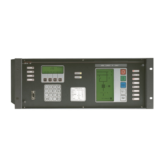
Following figure shown the common front, where there are the alphanumeric and graphic displays, functional and numerical keyboard, and a local communications port. Figure 4.1 7IRD Front View. M7IRDA2003I 7IRD-A/J/M: Distribution Protection & Control Terminal © ZIV APLICACIONES Y TECNOLOGÍA, S.L.U. 2020... -
Page 29: Protection And Control Interconnection
7IRD IED’s have a standard 19” rack width, are 4 rack units high. The equipment is intended to be installed semi-flush mounted in panels. The enclosure colour of the unit is graphite. M7IRDA2003I 7IRD-A/J/M: Distribution Protection & Control Terminal © ZIV APLICACIONES Y TECNOLOGÍA, S.L.U. 2020... -
Page 30: Connection Elements
The electronic pc boards have screws that should be removed before proceeding with the board removal. Before performing this operation, the protection terminal should be Out of Service. M7IRDA2003I 7IRD-A/J/M: Distribution Protection & Control Terminal © ZIV APLICACIONES Y TECNOLOGÍA, S.L.U. 2020... -
Page 31: Settings
5.1.2 General Settings ....................5-2 5.1.3 Protection Settings ....................5-3 5.1.4 Recloser Settings (7IRD-A/J Models) ..............5-4 5.1.5 Logic Settings ...................... 5-6 5.1.6 Breaker Monitoring Settings ................5-7 ... -
Page 32: Protection Subsystem Settings
Phase CT Ratio 1 - 3000 Ground CT Ratio 1 - 3000 Open Breaker Status 1 - 0 Event masking (only through communications) YES / NO M7IRDA2003I 7IRD-A/J/M: Distribution Protection & Control Terminal © ZIV APLICACIONES Y TECNOLOGÍA, S.L.U. 2020... -
Page 33: Protection Settings
(0.1 - 12) In 0.01 A Optional Ground Ratio (0.1 - 30) In 0.01 A Time Delay 0 - 100s 0.01s Torque Control (Pickup Blocking Enable) YES / NO M7IRDA2003I 7IRD-A/J/M: Distribution Protection & Control Terminal © ZIV APLICACIONES Y TECNOLOGÍA, S.L.U. 2020... -
Page 34: Recloser Settings (7Ird-A/J Models)
0.05 - 300 s 0.01 s Sequence Check Time 0.05 - 0.35 s 0.01 s Time Delay on Manual Close 0.05 - 300 s 0.01 s M7IRDA2003I 7IRD-A/J/M: Distribution Protection & Control Terminal © ZIV APLICACIONES Y TECNOLOGÍA, S.L.U. 2020... - Page 35 Recloser Reset Timer is Active After 1st, 2nd, 3rd or 4th Reclose Attempt Recloser Reset Timer is Active After External Manual Close Recloser Reset Timer is Active After Recloser Manual Close M7IRDA2003I 7IRD-A/J/M: Distribution Protection & Control Terminal © ZIV APLICACIONES Y TECNOLOGÍA, S.L.U. 2020...
-
Page 36: Logic Settings
Trip Output Seal-in Enable YES / NO Breaker Open Failure Time 0.02 - 2s 0.01s Breaker Close Failure Time 0.02 - 2s 0.01s Recloser Close Enable YES / NO M7IRDA2003I 7IRD-A/J/M: Distribution Protection & Control Terminal © ZIV APLICACIONES Y TECNOLOGÍA, S.L.U. 2020... -
Page 37: Breaker Monitoring Settings
Average Calculation Time Interval 1 - 15 min Data Record Interval 1 min. - 24.00 h. Day Calendar Mask Sunday to Saturday (YES/NO) Hour Range 0 - 24.00h. M7IRDA2003I 7IRD-A/J/M: Distribution Protection & Control Terminal © ZIV APLICACIONES Y TECNOLOGÍA, S.L.U. 2020... -
Page 38: Oscillographic Recording (Optional)
Ground 2 Instantaneous (G2I) YES / NO Channels Setting Range Step Pre-fault Time 1 - 2 cycles Oscillographic Record Length 20 - 300 cycles Analogic Channels 0-3 (four channels) M7IRDA2003I 7IRD-A/J/M: Distribution Protection & Control Terminal © ZIV APLICACIONES Y TECNOLOGÍA, S.L.U. 2020... -
Page 39: Control Subsystem Settings
1 - 3000 Transducers (*) Constant 0.00 to 99999.99 Quantity kw, kVAr, A, kV Type 2.5; 0.5; 1.0; 0-1 mA (*)The transducer output type depending on the model. M7IRDA2003I 7IRD-A/J/M: Distribution Protection & Control Terminal © ZIV APLICACIONES Y TECNOLOGÍA, S.L.U. 2020... -
Page 40: Time Settings
Voltage Absence Level 10 to 85 Vac Note: Time, Logic and Analogic settings are an example of possible settings because these are definite by equipment configuration. M7IRDA2003I 5-10 7IRD-A/J/M: Distribution Protection & Control Terminal © ZIV APLICACIONES Y TECNOLOGÍA, S.L.U. 2020... -
Page 41: Description Of Operation Of Protection Subsystem
6.7.2 Breaker Open and Breaker Close Failure Time ..........6-21 6.7.3 Manual Closing through Recloser (7IRD-A/J Models) ........6-21 Trip and Close Coil Circuit Supervision ............6-22 6.8.1 Trip Coil Circuit ....................6-23 ... - Page 42 6.14 Oscillographic Register (Optional) ..............6-34 6.15 Inputs, Outputs and LED Targets ..............6-36 6.15.1 Inputs ......................... 6-36 6.15.2 Auxiliary Outputs and Trip Contact Outputs ............6-38 6.15.3 LED Targets ...................... 6-43 ...
-
Page 43: Overcurrent Elements
Chapter 6. Description of Operation of Protection Subsystem Overcurrent Elements 7IRD-A/J/M IED’s provide four directional overcurrent protection elements: three-phase and ground. 7IRD-A/M Model Each of these elements consists of an Instantaneous and a Time Overcurrent measuring element. The Instantaneous measuring element is also equipped with an adjustable timer which can be enabled or disabled. -
Page 44: Time/ Current Characteristics
Figures 6.1, 6.2 and 6.3 show the pre-programmed time/current characteristic curves provided by the protection. Figure 6.1 Inverse Time / Current Characteristic. Index measured pickup M7IRDA2003I 7IRD-A/J/M: Distribution Protection & Control Terminal © ZIV APLICACIONES Y TECNOLOGÍA, S.L.U. 2020... - Page 45 Chapter 6. Description of Operation of Protection Subsystem Figure 6.2 Very Inverse Time / Current Characteristic. measured x Index pickup M7IRDA2003I 7IRD-A/J/M: Distribution Protection & Control Terminal © ZIV APLICACIONES Y TECNOLOGÍA, S.L.U. 2020...
- Page 46 Chapter 6. Description of Operation of Protection Subsystem Figure 6.3 Extremely Inverse Time / Current Characteristic. measured x Index pickup M7IRDA2003I 7IRD-A/J/M: Distribution Protection & Control Terminal © ZIV APLICACIONES Y TECNOLOGÍA, S.L.U. 2020...
-
Page 47: Instantaneous Elements
The actuation of the Instantaneous 2 (Phase and Ground) elements on 7IRD-J model, inhibit the actuation of the Recloser. 6.1.3 Overcurrent Units Block Diagrams 7IRD-A/M Model Figure 6.4 Overcurrent Unit Block Diagram (7IRD-A/M Model). M7IRDA2003I 7IRD-A/J/M: Distribution Protection & Control Terminal © ZIV APLICACIONES Y TECNOLOGÍA, S.L.U. 2020... -
Page 48: Torque Control (Pickup Blocking Enable)
For each one of the Torque Control inputs, there is an Enable setting within each protection element menu in the display. To use these Logic Input Signals, Status Contact Inputs must be programmed for this application. M7IRDA2003I 7IRD-A/J/M: Distribution Protection & Control Terminal © ZIV APLICACIONES Y TECNOLOGÍA, S.L.U. 2020... -
Page 49: Trip Blocking And Time Delay Disable
Additionally, one or more of the Auxiliary Contact Outputs must be configured as a Breaker Failure Output (FI) to produce a contact output for initiating backup tripping. M7IRDA2003I 7IRD-A/J/M: Distribution Protection & Control Terminal © ZIV APLICACIONES Y TECNOLOGÍA, S.L.U. 2020... -
Page 50: Open Phase Element
Phase or Ground, Time or Instantaneous Overcurrent elements are picked up. If this function is disabled, positive and negative sequence current measurement is still provided for metering display purposes. M7IRDA2003I 6-10 7IRD-A/J/M: Distribution Protection & Control Terminal © ZIV APLICACIONES Y TECNOLOGÍA, S.L.U. 2020... -
Page 51: Residual Current Element
Time Delay setting, a Trip Output occurs (S_RESIDUAL). The Residual Current Unit Detection can be disabled with the element Enable setting but is automatically disabled when the Ground Time Overcurrent element picks up. M7IRDA2003I 6-11 7IRD-A/J/M: Distribution Protection & Control Terminal © ZIV APLICACIONES Y TECNOLOGÍA, S.L.U. 2020... -
Page 52: General Settings
“0”, or as contact normally (with breaker closed), which corresponds to the setting “1”. The state of the breaker is used by the Recloser (7IRD-A/J Models) to define the state of Block due to Open Breaker and the beginning of the reclosing cycle. Moreover, it is linked to the Breaker operation which occur from the keyboard and via communications. -
Page 53: Recloser (7Ird-A/J Models)
Close set by the user. If the fault has been successfully cleared, the reclose sequence continues with the activation of the Reclose Sequence in Progress (CC) signal. M7IRDA2003I 6-13 7IRD-A/J/M: Distribution Protection & Control Terminal © ZIV APLICACIONES Y TECNOLOGÍA, S.L.U. 2020... - Page 54 Reclose Inhibit Timer times out and the Reclose Inhibit (INR) input is present, the Recloser status changes to Recloser Lockout Due To Unsatisfied Reclosing Conditions. M7IRDA2003I 6-14 7IRD-A/J/M: Distribution Protection & Control Terminal © ZIV APLICACIONES Y TECNOLOGÍA, S.L.U. 2020...
- Page 55 Chapter 6. Description of Operation of Protection Subsystem Figure 6.10 Recloser Flow Diagram (I). M7IRDA2003I 6-15 7IRD-A/J/M: Distribution Protection & Control Terminal © ZIV APLICACIONES Y TECNOLOGÍA, S.L.U. 2020...
- Page 56 Chapter 6. Description of Operation of Protection Subsystem Figure 6.11 Recloser Flow Diagram (II). M7IRDA2003I 6-16 7IRD-A/J/M: Distribution Protection & Control Terminal © ZIV APLICACIONES Y TECNOLOGÍA, S.L.U. 2020...
-
Page 57: Recloser Lockout
Recloser switches to the Recloser Reset state. If there is a trip before timing is completed, the Recloser switches to the Recloser Lockout Due To Switch-On-To-Fault state. M7IRDA2003I 6-17 7IRD-A/J/M: Distribution Protection & Control Terminal © ZIV APLICACIONES Y TECNOLOGÍA, S.L.U. 2020... -
Page 58: Manual And External Blocking
Recloser Block command while in the Recloser External Lockout state, the Recloser changes to the Recloser Blocked state which can only be reset by a Recloser Unblock command. M7IRDA2003I 6-18 7IRD-A/J/M: Distribution Protection & Control Terminal © ZIV APLICACIONES Y TECNOLOGÍA, S.L.U. 2020... -
Page 59: Definite Trip
Phase Time Ground Instantaneous Ground 1 Instantaneous Ground Time Ground Time Open Phase Phase 2 Instantaneous Residual Current Ground 2 Instantaneous Open Phase Residual Current M7IRDA2003I 6-19 7IRD-A/J/M: Distribution Protection & Control Terminal © ZIV APLICACIONES Y TECNOLOGÍA, S.L.U. 2020... - Page 60 No masking is YES in the setting. Therefore, you have to make sure that at least one measurement unit is not masked and is in an enable status. M7IRDA2003I 6-20 7IRD-A/J/M: Distribution Protection & Control Terminal © ZIV APLICACIONES Y TECNOLOGÍA, S.L.U. 2020...
-
Page 61: Logic
Chapter 6. Description of Operation of Protection Subsystem Logic The Logic settings include the following functions: Trip Seal-In, Breaker Open and Close Failure Time and Closing through the Recloser (7IRD-A/J Models). 6.7.1 Trip Seal-In The Trip Output Seal-In function is enabled by setting the Seal-In Enable to YES. Once a... -
Page 62: Trip And Close Coil Circuit Supervision
The Trip and Close Coil Circuit Supervision functions can be independently disabled. The block diagram depicting this feature (in the open breaker condition) is shown in the following figure. Figure 6.12 Trip/Close Coil Circuit Supervision Block Diagram. M7IRDA2003I 6-22 7IRD-A/J/M: Distribution Protection & Control Terminal © ZIV APLICACIONES Y TECNOLOGÍA, S.L.U. 2020... -
Page 63: Trip Coil Circuit
It is also necessary to take into account that for the Close Coil Circuit the activation time is about 20 sec, instead of the 5 sec for the Trip Coil Circuit. M7IRDA2003I 6-23 7IRD-A/J/M: Distribution Protection & Control Terminal © ZIV APLICACIONES Y TECNOLOGÍA, S.L.U. 2020... -
Page 64: Trip/Close Coil Circuit Supervision Input Programming
Figure 6.13 Trip/Close Output Supervision Block Diagram. The close output is monitored in a similar manner. Signal FSP-3 indicates an improper close operation. M7IRDA2003I 6-24 7IRD-A/J/M: Distribution Protection & Control Terminal © ZIV APLICACIONES Y TECNOLOGÍA, S.L.U. 2020... -
Page 65: Breaker Monitoring
Auxiliary Contact Outputs. On 7IRD-A/J models, this output will disable any further reclose initiation by placing the unit in Recloser Lockout Due To Open Breaker Status. This condition will reset only after a Manual Close Command or a loss of auxiliary power. -
Page 66: Change Settings Group
Control setting group by status contact inputs (E_DIG set to “1”) and by remote communications port (P_REM set to “1”) cannot be enabled simultaneously. M7IRDA2003I 6-26 7IRD-A/J/M: Distribution Protection & Control Terminal © ZIV APLICACIONES Y TECNOLOGÍA, S.L.U. 2020... -
Page 67: Event Record
Phase C Time Unit Pickup activation [0C] Ground Time Unit Pickup Phase A Instantaneous (7IRD-A/M) / Instantaneous 1 (7IRD-J) Unit Pickup Phase B Instantaneous (7IRD-A/M) / Instantaneous 1 (7IRD-J) Unit Pickup Phase C Instantaneous (7IRD-A/M) / Instantaneous 1... - Page 68 Phase C Time Unit Reset deactivation [10] Ground Time Unit Reset Phase A Instantaneous (7IRD-A/M) / Instantaneous 1 (7IRD-J) Unit Reset Phase B Instantaneous (7IRD-A/M) / Instantaneous 1 (7IRD-J) Unit Reset Phase C Instantaneous (7IRD-A/M) / Instantaneous 1...
- Page 69 Status Contact Input IN-4 Activation (expansion) Status Contact Input IN-5 Activation (expansion) Status Contact Input IN-6 Activation (expansion) Status Contact Input IN-7 Activation (expansion) Status Contact Input IN-8 Activation (expansion) M7IRDA2003I 6-29 7IRD-A/J/M: Distribution Protection & Control Terminal © ZIV APLICACIONES Y TECNOLOGÍA, S.L.U. 2020...
- Page 70 Current Detected With Open Breaker Status (52b contact) Breaker Close Command Failure Breaker Open Command Failure Breaker Close Command Breaker Open Command Excessive Number Of Trips M7IRDA2003I 6-30 7IRD-A/J/M: Distribution Protection & Control Terminal © ZIV APLICACIONES Y TECNOLOGÍA, S.L.U. 2020...
- Page 71 If the IED provide oscillographic register the Event Records consulting only can be effectuated via communications. M7IRDA2003I 6-31 7IRD-A/J/M: Distribution Protection & Control Terminal © ZIV APLICACIONES Y TECNOLOGÍA, S.L.U. 2020...
-
Page 72: Fault Reports
Chapter 8 offers the related information to consult the fault report using the HMI. If the IED provide Oscillographic Register, the Fault Report can’t be effectuated by HMI. M7IRDA2003I 6-32 7IRD-A/J/M: Distribution Protection & Control Terminal © ZIV APLICACIONES Y TECNOLOGÍA, S.L.U. 2020... -
Page 73: Metering History Log
Information - Records - Current History. This is explained in Chapter 8, Alphanumeric Keyboard and Display. If the IED has Oscillographic Register; this information only will be available through communications. M7IRDA2003I 6-33 7IRD-A/J/M: Distribution Protection & Control Terminal © ZIV APLICACIONES Y TECNOLOGÍA, S.L.U. 2020... -
Page 74: Oscillographic Register (Optional)
Start Function. The activation occurs when any of the selected protection elements pick up, and de-activation occurs when all selected elements are reset. M7IRDA2003I 6-34 7IRD-A/J/M: Distribution Protection & Control Terminal © ZIV APLICACIONES Y TECNOLOGÍA, S.L.U. 2020... - Page 75 If the Overwrite setting has been set to YES, once the memory is full, the next record will replace the oldest record that is erased. M7IRDA2003I 6-35 7IRD-A/J/M: Distribution Protection & Control Terminal © ZIV APLICACIONES Y TECNOLOGÍA, S.L.U. 2020...
-
Page 76: Inputs, Outputs And Led Targets
6.15 Inputs, Outputs and LED Targets 7IRD-A/J/M terminal units are provided with programmable inputs, outputs and LEDs enabling user configuration of flexible logic designs. The following paragraphs contain a description of the programming structure to configure protection inputs, outputs and signalling. Factory default settings may be modified using the ZiverCom ®... - Page 77 D output connected The status contact inputs leave the factory with an assigned configuration, but can be modified through the local communications port with ZiverCom ® M7IRDA2003I 6-37 7IRD-A/J/M: Distribution Protection & Control Terminal © ZIV APLICACIONES Y TECNOLOGÍA, S.L.U. 2020...
-
Page 78: Auxiliary Outputs And Trip Contact Outputs
6.15.2 Auxiliary Outputs and Trip Contact Outputs Auxiliary Outputs The 7IRD-A/J/M models have 8 physical outputs, seven configurable, and 8 virtual outputs, seven configurable. If there is an enlargement trip coil circuit, the virtual signal will be physical signals. - Page 79 ATDD_B Phase B Time Overcurrent Interlocked Pickup ATDD_C Phase C Time Overcurrent Interlocked Pickup ATDD_N Ground Time Overcurrent Interlocked Pickup Phase A Inst. (7IRD-A/M) / Inst. 1 (7IRD-J) AIDD_A Overcurrent Elements Trips. Overcurrent Interlocked Pickup Affected by their respective trip AIDD_B Phase B Inst.
- Page 80 (this time can be set independently for opening and closure). Breaker status AND logic and Open Breaker Overcurrent line current detect. M7IRDA2003I 6-40 7IRD-A/J/M: Distribution Protection & Control Terminal © ZIV APLICACIONES Y TECNOLOGÍA, S.L.U. 2020...
- Page 81 SUTM_C Phase C Time Overcurrent Mask Enabled Trip Output SUTM_N Ground Time Overcurrent Mask Enabled Trip Output Phase A Inst. (7IRD-A/M) / Inst. 1 (7IRD-J) SUIM_A Unit Trips. Affected by their Overcurrent Mask Enabled Trip Output corresponding trip mask. SUIM_B Phase B Inst.
- Page 82 Chapter 6. Description of Operation of Protection Subsystem Table 6-3: Auxiliary Outputs Name Description Function BI DD + BI FL (7IRD-A/J) The fault persists at the end of reclose sequences internal block of the Recloser due to a fault when energizing the line.
-
Page 83: Led Targets
OR gate, while the other has one input and can realize an OR or AND gate. Figure 6.16 LED Target Output Logic Cell Block Diagram. M7IRDA2003I 6-43 7IRD-A/J/M: Distribution Protection & Control Terminal © ZIV APLICACIONES Y TECNOLOGÍA, S.L.U. 2020... -
Page 84: Communications
Chapter 5. In the model 7IRD exist two controllers; one is for the communications port so that several ports can be established at one time. M7IRDA2003I 6-44 7IRD-A/J/M: Distribution Protection & Control Terminal © ZIV APLICACIONES Y TECNOLOGÍA, S.L.U. 2020... -
Page 85: Alarm Codes
E2PROM writing error 00 02 ADC alarm 00 04 ADC error 00 08 Low battery clock 00 10 Stopped clock 00 20 Input and/or output transducers error M7IRDA2003I 6-45 7IRD-A/J/M: Distribution Protection & Control Terminal © ZIV APLICACIONES Y TECNOLOGÍA, S.L.U. 2020... - Page 86 02 and 04 and 08 = 0E 01 and 02 and 04 and 08 = 0F Contact with the manufacturer if these alarm codes appear. M7IRDA2003I 6-46 7IRD-A/J/M: Distribution Protection & Control Terminal © ZIV APLICACIONES Y TECNOLOGÍA, S.L.U. 2020...
-
Page 87: Description Of Operation Of The Control Subsystem
Description of Operation of the Control Subsystem Operational Characteristics ................. 7-2 Control Unit ......................7-3 7.2.1 Elements of the Control Subsystem ..............7-6 7.2.2 Inputting Data to the Control Unit ................ 7-7 ... -
Page 88: Operational Characteristics
The Control Functions are the following: Local Control of the Position. Local Control of the Recloser (7IRD-A/J Models). Presentation of Local Alarms in Conventional Alarm Panel Format. Presentation of the Digital States of the Output Signals from the Control Subsystem. -
Page 89: Control Unit
Logic Operations. Each of these blocks determines an outcome (state of one or more signals) depending on the state of the Inputs of that block. The use of one or another block is determined by the Configuration. M7IRDA2003I 7IRD-A/J/M: Distribution Protection & Control Terminal © ZIV APLICACIONES Y TECNOLOGÍA, S.L.U. 2020... - Page 90 The Input as well as the Output Signals depends on the configuration loaded in the unit. The number of these Physical Signals depends on the specific model. M7IRDA2003I 7IRD-A/J/M: Distribution Protection & Control Terminal © ZIV APLICACIONES Y TECNOLOGÍA, S.L.U. 2020...
- Page 91 Chapter 7. Description of Operation of the Control Subsystem Figure 7.1 Control Subsystem Block Diagram. M7IRDA2003I 7IRD-A/J/M: Distribution Protection & Control Terminal © ZIV APLICACIONES Y TECNOLOGÍA, S.L.U. 2020...
-
Page 92: Elements Of The Control Subsystem
Protection, Physical Inputs and Logic Outputs, will determine whether or not to present an alarm message in the Graphic Display and, if so, which is the corresponding associated message. M7IRDA2003I 7IRD-A/J/M: Distribution Protection & Control Terminal © ZIV APLICACIONES Y TECNOLOGÍA, S.L.U. 2020... -
Page 93: Inputting Data To The Control Unit
Control Orders are orders that arrive through the Central Unit from the SCADA. Automatism Orders are orders generated by one or more of the automatisms residing in the Central Unit. M7IRDA2003I 7IRD-A/J/M: Distribution Protection & Control Terminal © ZIV APLICACIONES Y TECNOLOGÍA, S.L.U. 2020... -
Page 94: Inputs From The Protection Subsystem
Panel and/or to the Single-wire objects. Inputs from Measurement Transducers. The signals called SC are those that get to the Control Subsystem from the measurement transducers. M7IRDA2003I 7IRD-A/J/M: Distribution Protection & Control Terminal © ZIV APLICACIONES Y TECNOLOGÍA, S.L.U. 2020... -
Page 95: Hmi Inputs (Control Hmi)
7.2.3.b Signals sent to the Protection Subsystem The signals sent to the Protection Subsystem are Output orders from the Logic, assigned by the Output Connection Process. M7IRDA2003I 7IRD-A/J/M: Distribution Protection & Control Terminal © ZIV APLICACIONES Y TECNOLOGÍA, S.L.U. 2020... -
Page 96: Physical Outputs
The corresponding screen will display the state (ON - OFF) of the LEDs associated with the Protection Subsystem accessible through the Protection Input signals (EP). M7IRDA2003I 7-10 7IRD-A/J/M: Distribution Protection & Control Terminal © ZIV APLICACIONES Y TECNOLOGÍA, S.L.U. 2020... -
Page 97: Alphanumeric Keypad And Display
Alphanumeric Keypad and Display Alphanumeric Display and Keypad ..............8-2 Keys, Functions and Operation Modes ............... 8-3 Access to Functions Using Key F2 ..............8-6 8.3.1 Last Trip Indication and Recloser Status ............8-6 ... -
Page 98: Alphanumeric Display And Keypad
(ENT) and the exit key (ESC). Figure 8.2 Keypad. The access to the functions can be done by two different modes: using a single key (F2) or using the keypad. M7IRDA2003I 7IRD-A/J/M: Distribution Protection & Control Terminal © ZIV APLICACIONES Y TECNOLOGÍA, S.L.U. 2020... -
Page 99: Keys, Functions And Operation Modes
This function is only needed when changing a setting. Key to return to the Default Screen Pressing this key from any menu or submenu returns the system directly to the default screen. M7IRDA2003I 7IRD-A/J/M: Distribution Protection & Control Terminal © ZIV APLICACIONES Y TECNOLOGÍA, S.L.U. 2020... - Page 100 Another mode of access consists in going through the menus by the selection keys () and confirm the selection option pressing ENT. M7IRDA2003I 7IRD-A/J/M: Distribution Protection & Control Terminal © ZIV APLICACIONES Y TECNOLOGÍA, S.L.U. 2020...
- Page 101 To go out from a menu or setting, press ESC key. To go out for an information screen press ENT or ESC. In all cases the back menu will appear. M7IRDA2003I 7IRD-A/J/M: Distribution Protection & Control Terminal © ZIV APLICACIONES Y TECNOLOGÍA, S.L.U. 2020...
-
Page 102: Access To Functions Using Key F2
XXXX is replaced by the Phase or Ground elements that have generated the trip. For example, a trip due to an A Phase-to-Ground Fault produces TOC_AG. Open Phase Trip: TEM_F Residual Current Trip: TEM_R M7IRDA2003I 7IRD-A/J/M: Distribution Protection & Control Terminal © ZIV APLICACIONES Y TECNOLOGÍA, S.L.U. 2020... -
Page 103: Screen Sequences Using F2
At the first row will appear the status of the Recloser: BLOCKED, UNBLOCKED or NOT IN SERVICE. At the second one appear the operation: BLOCKED or UNBLOCKED. M7IRDA2003I 7IRD-A/J/M: Distribution Protection & Control Terminal © ZIV APLICACIONES Y TECNOLOGÍA, S.L.U. 2020... - Page 104 RECLOSE COUNT RESET. Pressing again F2 the cycle can be repeat. The system automatically returns to the default screen if no keys entries are made after 20 seconds. M7IRDA2003I 7IRD-A/J/M: Distribution Protection & Control Terminal © ZIV APLICACIONES Y TECNOLOGÍA, S.L.U. 2020...
-
Page 105: Function Access Using The Keypad
1 - OPERATION ENABLE 2 - ACTIVE GROUP 2 - CONFIGURE INPUTS 3 - CHANGE SETTINGS 3 - CONFIGURE OUTPUTS 4 - INFORMATION 4 - LANGUAGE 5 - FREQUENCY M7IRDA2003I 7IRD-A/J/M: Distribution Protection & Control Terminal © ZIV APLICACIONES Y TECNOLOGÍA, S.L.U. 2020... - Page 106 0 - GROUP 1 (ACTIVE) 1 - OPERATIONS 1 - GROUP 2 (RESERVE) 2 - ACTIVE GROUP 2 - GROUP 3 (RESERVE) 3 - CHANGE SETTINGS 4 - INFORMATION M7IRDA2003I 8-10 7IRD-A/J/M: Distribution Protection & Control Terminal © ZIV APLICACIONES Y TECNOLOGÍA, S.L.U. 2020...
- Page 107 2 - CR RATIO GROUND 3 - CHANGE SETTINGS 3 - BREAKER SUPV 3 - OPEN BREAKER STATU 4 - INFORMATION 4 - HISTORICAL RECORDS 5 - OSCILLOGRAPHY M7IRDA2003I 8-11 7IRD-A/J/M: Distribution Protection & Control Terminal © ZIV APLICACIONES Y TECNOLOGÍA, S.L.U. 2020...
- Page 108 Chapter 8. Alphanumeric Keypad and Display Protection Settings: HMI Access. 7IRD-A Model 0 - CONFIGURATION 0 - GENERAL 0 - PH TIME O/C 1 - OPERATIONS 1 - PROTECTION 1 - GR TIME O/C 2 - ACTIVE GROUP 2 - RECLOSER...
- Page 109 5 - GR INSTANT. 2 5 - GR T O/C INTERLOCK 6 - OSCILLOGRAPHY 6 - SUSTAINED GROUND 7 - PHASE UNBALANCE 8 - BREAKERFAILURE M7IRDA2003I 8-13 7IRD-A/J/M: Distribution Protection & Control Terminal © ZIV APLICACIONES Y TECNOLOGÍA, S.L.U. 2020...
- Page 110 5 - GR INSTANT. 2 1 - SUSTAINED GR PKUP 6 - OSCILLOGRAPHY 6 - SUSTAINED GROUND 2 - SUSTAINED GR TIME 7 - PHASE UNBALANCE 8 - BREAKERFAILURE M7IRDA2003I 8-14 7IRD-A/J/M: Distribution Protection & Control Terminal © ZIV APLICACIONES Y TECNOLOGÍA, S.L.U. 2020...
- Page 111 4 - SUSTAINED GROUND 4 - GR DEFINITE TIME 5 - OSCILLOGRAPHY 5 - PHASE UNBALANCE 5 - GR T O/C INTERLOCK 6 - BREAKERFAILURE M7IRDA2003I 8-15 7IRD-A/J/M: Distribution Protection & Control Terminal © ZIV APLICACIONES Y TECNOLOGÍA, S.L.U. 2020...
- Page 112 1 - PH O/C PICKUP 5 - OSCILLOGRAPHY 5 - PHASE UNBALANCE 2 - GR O/C PICKUP 6 - BREAKERFAILURE 3 - BREAKER FAIL TIME M7IRDA2003I 8-16 7IRD-A/J/M: Distribution Protection & Control Terminal © ZIV APLICACIONES Y TECNOLOGÍA, S.L.U. 2020...
- Page 113 Chapter 8. Alphanumeric Keypad and Display Recloser Settings: HMI Access (7IRD-A/J Models) 0 - CONFIGURATION 0 - GENERAL 0 - RECL. IN SERVICE 1 - OPERATIONS 1 - PROTECTION 1 - RECLOSER TIMERS 2 - ACTIVE GROUP 2 - RECLOSER...
- Page 114 3 - BREAKER SUPV 3 - TRIP COIL CKT SUPV 4 - INFORMATION 4 - HISTORICAL RECORDS 4 - CLS COIL CKT SUPV 5 - OSCILLOGRAPHY M7IRDA2003I 8-18 7IRD-A/J/M: Distribution Protection & Control Terminal © ZIV APLICACIONES Y TECNOLOGÍA, S.L.U. 2020...
- Page 115 3 - RECORDS* 4 - INFORMATION 4 - STATUS 5 - METERING (*) If the equipment have Oscillographic function, Records will be available only through communications. M7IRDA2003I 8-19 7IRD-A/J/M: Distribution Protection & Control Terminal © ZIV APLICACIONES Y TECNOLOGÍA, S.L.U. 2020...
- Page 116 1 - CONFIGURATION 1 - COMMUNICATIONS 1 - REMOTE SETTING 2 - TRIPS 2 - DATA & TIME 3 - RECORDS 4 - STATUS 5 - METERING M7IRDA2003I 8-20 7IRD-A/J/M: Distribution Protection & Control Terminal © ZIV APLICACIONES Y TECNOLOGÍA, S.L.U. 2020...
- Page 117 3 - CHANGE SETTINGS 3 - RECORDS 0 - CURRENTS 4 - INFORMATION 4 - STATUS 1 - IMAX. 5 - METERING 2 - SEQUENCE CURRENTS M7IRDA2003I 8-21 7IRD-A/J/M: Distribution Protection & Control Terminal © ZIV APLICACIONES Y TECNOLOGÍA, S.L.U. 2020...
-
Page 118: Control Function Access
6 - FREQUENCY 0 - CONFIGURATION 0 - PASSWORDS 1 - CHANGE SETTINGS 1 - COMMUNICATIONS 2 - LOAD CONFIG PROGRAM 2 - DATE AND TIME M7IRDA2003I 8-22 7IRD-A/J/M: Distribution Protection & Control Terminal © ZIV APLICACIONES Y TECNOLOGÍA, S.L.U. 2020... - Page 119 1 - TIMER 0 - ALARM LEVEL U0 2 - LOAD CONFIG PROGRAM 2 - LOGICS 1 - NOT USED 3 - ANALOGICS 2 - NOT USED M7IRDA2003I 8-23 7IRD-A/J/M: Distribution Protection & Control Terminal © ZIV APLICACIONES Y TECNOLOGÍA, S.L.U. 2020...
- Page 120 Chapter 8. Alphanumeric Keypad and Display M7IRDA2003I 8-24 7IRD-A/J/M: Distribution Protection & Control Terminal © ZIV APLICACIONES Y TECNOLOGÍA, S.L.U. 2020...
-
Page 121: Local Interface: Graphic Display
Local Interface: Graphic Display General ........................ 9-2 Symbols Associated with the Graphic Display ............ 9-3 Accessing the Information ................... 9-6 9.3.1 Alarm Panel ......................9-7 9.3.2 Information about the State of Inputs/Outputs and Active LEDs ......9-8 ... -
Page 122: General
The elements represented depend on the specific model, and the information associated with each Single-Wire Object depends on the Configuration of each specific unit. M7IRDA2003I 7IRD-A/J/M: Distribution Protection & Control Terminal © ZIV APLICACIONES Y TECNOLOGÍA, S.L.U. 2020... -
Page 123: Symbols Associated With The Graphic Display
Pulled out closed Pulled out open Recloser In Service Out of Service Capacitor Bank Control Automatic Manual Voltage Regulator Automatic Manual Figure 9.2 Device Representation Symbols. M7IRDA2003I 7IRD-A/J/M: Distribution Protection & Control Terminal © ZIV APLICACIONES Y TECNOLOGÍA, S.L.U. 2020... - Page 124 - Open Breaker Position (contact type "b") - Closed Breaker Position (contact type "a") - Unplugged Breaker Mechanism Position - Pulled out Breaker Mechanism Position M7IRDA2003I 7IRD-A/J/M: Distribution Protection & Control Terminal © ZIV APLICACIONES Y TECNOLOGÍA, S.L.U. 2020...
- Page 125 These orders can be: - Busbar Disconnector “OPEN Order” - Busbar Disconnector “CLOSE Order” - Ground Breaker “OPEN Order” - Ground Breaker “CLOSE Order” M7IRDA2003I 7IRD-A/J/M: Distribution Protection & Control Terminal © ZIV APLICACIONES Y TECNOLOGÍA, S.L.U. 2020...
-
Page 126: Accessing The Information
Screen of Digital Outputs from the Control Subsystem (SD) Protection Input Screen (EP) Protection LED Screen (LP) Measurement and Counter Screen (there can be several) (7IRD-A/J Models) Date and Time Screen The signals that appear on each of these screens depends on the Configuration and, consequently, on the specific model. -
Page 127: Alarm Panel
Alarms are acknowledged with the function key associated with the Alphanumeric Display, F1. Whenever this key is pressed, the effect is extended to all the alarms. M7IRDA2003I 7IRD-A/J/M: Distribution Protection & Control Terminal © ZIV APLICACIONES Y TECNOLOGÍA, S.L.U. 2020... -
Page 128: Information About The State Of Inputs/Outputs And Active Leds
The third frame displays the values of the Counters. On 7IRD-A/J Models, the last rectangle presents the number of reclosings produced: the first number displays those produced counting only the first of each cycle and the second number displays the total reclosings minus those accumulated in the preceding counter. -
Page 129: Date And Time Information
The last screen before returning to the default display presents the Date and Time in the centre of the screen as shown in figure on the right. Figure 9.8 Date and Time Screen. M7IRDA2003I 7IRD-A/J/M: Distribution Protection & Control Terminal © ZIV APLICACIONES Y TECNOLOGÍA, S.L.U. 2020... -
Page 130: Control Function Operations
LINE 1: ORDER NOT EXECUTABLE LINE 2: DISCHARGE INTERLOCKING POSITION IN REMOTE CONTROL M7IRDA2003I 9-10 7IRD-A/J/M: Distribution Protection & Control Terminal © ZIV APLICACIONES Y TECNOLOGÍA, S.L.U. 2020... -
Page 131: Procedure For Opening/Closing Breakers And Disconnecting Switches
- Change of state of the device upon which the order is executed. - Order Failure signal if such is the outcome. - Order Executed signal. M7IRDA2003I 9-11 7IRD-A/J/M: Distribution Protection & Control Terminal © ZIV APLICACIONES Y TECNOLOGÍA, S.L.U. 2020... -
Page 132: Procedure For Placing A Breaker In Discharge
Digital Output (for example, obstruction to operating on disconnecting switches, etc.). M7IRDA2003I 9-12 7IRD-A/J/M: Distribution Protection & Control Terminal © ZIV APLICACIONES Y TECNOLOGÍA, S.L.U. 2020... -
Page 133: Procedure For Operating On Logic Devices
Each time this key is pressed, the effect is extended to all the alarms. The evolution of states of any one of the alarms is indicated in the flow chart of following figure. Figure 9.9 Alarm Management Sequence. M7IRDA2003I 9-13 7IRD-A/J/M: Distribution Protection & Control Terminal © ZIV APLICACIONES Y TECNOLOGÍA, S.L.U. 2020... - Page 134 Blinking Text: signal associated with the active or inactive alarm and alarm not acknowledged. No text: signal associated with the inactive alarm and alarm acknowledged. M7IRDA2003I 9-14 7IRD-A/J/M: Distribution Protection & Control Terminal © ZIV APLICACIONES Y TECNOLOGÍA, S.L.U. 2020...
-
Page 135: 10. Receiving Tests
Residual Current Test ..................10-6 10.5.5 Breaker Failure Test ..................10-6 10.5.6 Recloser Test (7IRD-A/J Models) ..............10-7 10.5.7 Trip/Close Coil Circuit Supervision Input Test ..........10-8 10.6 Control Subsystem Receiving Tests ..............10-8 ... -
Page 136: General
It must be emphasized that the Accuracy of the test will depend on the instruments used for measuring as well as the source signals used. Therefore, tests performed with secondary equipment should focus on operation verification and not on measuring Accuracy. M7IRDA2003I 10-2 7IRD-A/J/M: Distribution Protection & Control Terminal © ZIV APLICACIONES Y TECNOLOGÍA, S.L.U. 2020... -
Page 137: Preliminary Inspection
Control Subsystem and test to see that the state of the contacts for CON1C and CON2C change and that the LED Ready is on. M7IRDA2003I 10-3 7IRD-A/J/M: Distribution Protection & Control Terminal © ZIV APLICACIONES Y TECNOLOGÍA, S.L.U. 2020... -
Page 138: Protection Subsystem Reception Tests
1 x X 1.05 x X 0.95 x X Interval for pickup and tripping within lower current ranges can be extended to X 20 mA. M7IRDA2003I 10-4 7IRD-A/J/M: Distribution Protection & Control Terminal © ZIV APLICACIONES Y TECNOLOGÍA, S.L.U. 2020... - Page 139 For each time/current characteristic, tripping time is given by the selected Time Dial Setting and the applied current (multiple of pickup current setting; see Time Characteristic Curves figures on Chapter 6). Tolerance is 5% of the current value. M7IRDA2003I 10-5 7IRD-A/J/M: Distribution Protection & Control Terminal © ZIV APLICACIONES Y TECNOLOGÍA, S.L.U. 2020...
-
Page 140: Open Phase Test
Breaker Failure element should activate the Auxiliary Contact Output. Gradually reduce the current until the Breaker Failure element reaches a stable reset. Verify that this occurs between 5% of the setting value. M7IRDA2003I 10-6 7IRD-A/J/M: Distribution Protection & Control Terminal © ZIV APLICACIONES Y TECNOLOGÍA, S.L.U. 2020... -
Page 141: Recloser Test (7Ird-A/J Models)
This way of action could be sufficient to cause the instantaneous element to trip, and at the same time, to stop it from seeing the current circulating before starting time. M7IRDA2003I 10-7 7IRD-A/J/M: Distribution Protection & Control Terminal © ZIV APLICACIONES Y TECNOLOGÍA, S.L.U. 2020... -
Page 142: Trip/Close Coil Circuit Supervision Input Test
- Test of Digital Inputs - Test of Digital Outputs and visual signals - Measurement Test Figure 10.3 Test Configuration (I). M7IRDA2003I 10-8 7IRD-A/J/M: Distribution Protection & Control Terminal © ZIV APLICACIONES Y TECNOLOGÍA, S.L.U. 2020... -
Page 143: Digital Inputs Test
Repeat the process until you have activated each and every Digital Input corresponding to the unit being tested. Figure 10.5 Connection for the Digital Inputs Test. M7IRDA2003I 10-9 7IRD-A/J/M: Distribution Protection & Control Terminal © ZIV APLICACIONES Y TECNOLOGÍA, S.L.U. 2020... -
Page 144: Digital Outputs And Leds Test
V Measured (V) CONV1 (mA) 54.8-55.2 2.19-2.20 99.5-100.5 3.98-4.02 124.4-125.6 4.975-5.025 Check that the current described in the same table appears through the Transducer Output. M7IRDA2003I 10-10 7IRD-A/J/M: Distribution Protection & Control Terminal © ZIV APLICACIONES Y TECNOLOGÍA, S.L.U. 2020... -
Page 145: Communication Test
Afterwards, connect the Power Supply and connect to the terminal unit through the Remote ® Communications Port. Activate the “cyclical” mode in the ZiverCom software program and verify that time actualizes properly. M7IRDA2003I 10-11 7IRD-A/J/M: Distribution Protection & Control Terminal © ZIV APLICACIONES Y TECNOLOGÍA, S.L.U. 2020... -
Page 146: Installation
14 AWG. Ground wire length should be minimized and should not exceed 12”. The ground terminal of the enclosure located on the rear panel of the equipment should also be grounded. M7IRDA2003I 10-12 7IRD-A/J/M: Distribution Protection & Control Terminal © ZIV APLICACIONES Y TECNOLOGÍA, S.L.U. 2020... - Page 147 PROCOME 3.0 Communications Protocol Settings ....................... A-2 A.1.1 Configuration Settings ..................A-2 A.1.2 Logic Settings ...................... A-2 Description of Operation ..................A-3 A.2.1 General Settings ....................A-3 A.2.2 Logic ........................A-3 ...
-
Page 148: Procome 3.0 Communications Protocol
Settings for establishing communication through the Remote Port. Only can be modified through ZiverCom © A.1.2 Logic Settings Logic Setting Range Pickup Report YES / NO M7IRDA2003I 7IRD-A/J/M: Distribution Protection & Control Terminal © ZIV APLICACIONES Y TECNOLOGÍA, S.L.U. 2020... -
Page 149: Description Of Operation
If the Directional elements are not in a stable situation they should not be unmasked. In the particular case of the Ground Directional, it should not be unmasked unless it is to analyze some very specific situation. M7IRDA2003I 7IRD-A/J/M: Distribution Protection & Control Terminal © ZIV APLICACIONES Y TECNOLOGÍA, S.L.U. 2020... -
Page 150: Fault Report
Digital Input or to its negated. A.2.6 Communicating with the Unit Using the PROCOME profile, it is possible to communicate with the unit to request control changes and to execute orders. M7IRDA2003I 7IRD-A/J/M: Distribution Protection & Control Terminal © ZIV APLICACIONES Y TECNOLOGÍA, S.L.U. 2020... -
Page 151: Alphanumeric Keypad And Display
This password must have 8 characters, which will be entered using the numerical keys and the key corresponding to a dot. M7IRDA2003I 7IRD-A/J/M: Distribution Protection & Control Terminal © ZIV APLICACIONES Y TECNOLOGÍA, S.L.U. 2020... -
Page 152: Settings
The variations in the settings menus described in the preceding sections are reflected in the information menus, with the same layout shown. Note that the Information menu only allows viewing the established settings and does not allow modifying them. M7IRDA2003I 7IRD-A/J/M: Distribution Protection & Control Terminal © ZIV APLICACIONES Y TECNOLOGÍA, S.L.U. 2020... -
Page 153: Dnp 3.0 Communications Protocol
DNP 3.0 Communications Protocol Physical Architecture ................... B-2 Settings ....................... B-2 Description of Operation ..................B-3 B.3.1 DNP 3.0 Protocol ....................B-3 B.3.2 Communications ....................B-8 B.3.2.a Communication with the Equipment ..............B-8 ... -
Page 154: Physical Architecture
0 - 32767 1 ms Metering Changes Settings Setting Range Step % Change metering 0.00 - 100% 0.01 % Settings independents for metering changes from 0 to 15 M7IRDA2003I 7IRD-A/J/M: Distribution Protection & Control Terminal © ZIV APLICACIONES Y TECNOLOGÍA, S.L.U. 2020... -
Page 155: Description Of Operation
Number of retries of the Application Layer (N7). The default value is 0 (zero), indicating that no retransmission will be attempted. Pre-Transmission Time setting which generates the number of warning characters. M7IRDA2003I 7IRD-A/J/M: Distribution Protection & Control Terminal © ZIV APLICACIONES Y TECNOLOGÍA, S.L.U. 2020... - Page 156 If it is adjusted to 100%, analogical changes in this measure will not be recorded which is then understood as being in a deactivated state. M7IRDA2003I 7IRD-A/J/M: Distribution Protection & Control Terminal © ZIV APLICACIONES Y TECNOLOGÍA, S.L.U. 2020...
- Page 157 16-Bit Analog Change Event with Time 129,130 0x28 to Class Analog Output Status – All variations 16-Bit Analog Output Block 3,4,5,6 0x17,28 Time and Date count=1 Time Delay Fine count=1 M7IRDA2003I 7IRD-A/J/M: Distribution Protection & Control Terminal © ZIV APLICACIONES Y TECNOLOGÍA, S.L.U. 2020...
- Page 158 (52-2). This object sets the number of milliseconds to transpire between the remote station's reception of the first bit of the first byte of the request and the transmission time of the first bit of the first byte of the response. M7IRDA2003I 7IRD-A/J/M: Distribution Protection & Control Terminal © ZIV APLICACIONES Y TECNOLOGÍA, S.L.U. 2020...
- Page 159 Invalid value (quiescent) -20 0 % Invalid value (quiescent) 6553 Distance from 0 % 100 % 32767 Distance from 100 % >100 % Invalid value (quiescent) M7IRDA2003I 7IRD-A/J/M: Distribution Protection & Control Terminal © ZIV APLICACIONES Y TECNOLOGÍA, S.L.U. 2020...
-
Page 160: Communications
5 - UNSOL DELAY REPORT, 6 - ECHO CTRL ENABLE 7 - N2 RETRIES 8 - PRE-TRANSM. TIME 9 - FIXED DELAY 10 - MAX. RANDOM DELAY M7IRDA2003I 7IRD-A/J/M: Distribution Protection & Control Terminal © ZIV APLICACIONES Y TECNOLOGÍA, S.L.U. 2020... -
Page 161: Information Access
The previous options are in the same position at information menu too. It’s important to remember that at information menu the settings can be shown but they can’t be modified. M7IRDA2003I 7IRD-A/J/M: Distribution Protection & Control Terminal © ZIV APLICACIONES Y TECNOLOGÍA, S.L.U. 2020... - Page 162 Annex B. DNP 3.0 Communications Protocol M7IRDA2003I B-10 7IRD-A/J/M: Distribution Protection & Control Terminal © ZIV APLICACIONES Y TECNOLOGÍA, S.L.U. 2020...
-
Page 163: Schemes And Drawings
Schemes and Drawings Dimension and Drill Hole Schemes 7IRD (4U x 1 rack) >>4BF0100/0012 External Connection Schemes 7IRD-A >>3RX0172/0031 (generic) 7IRD-J >>3RX0172/0030 (generic) 7IRD-M >>3RX0172/0037 (generic) -
Page 175: List Of Illustrations And Tables
List of Illustrations and Tables... -
Page 176: List Of Figures
Figure 6.3 Extremely Inverse Time / Current Characteristic..........6-6 Figure 6.4 Overcurrent Unit Block Diagram (7IRD-A/M Model)........... 6-7 Figure 6.5 Overcurrent Unit Block Diagram (7IRD-J Model)..........6-8 Figure 6.6 Breaker Failure Element Block Diagram. - Page 177 Annex D. List of Illustrations and Tables DNP 3.0 Communications Protocol ................ B-1 Figure B.1 7IRD Rear View with Two Communications Ports..........B-2 M7IRDA2003I 7IRD-A/J/M: Distribution Protection & Control Terminal © ZIV APLICACIONES Y TECNOLOGÍA, S.L.U. 2020...
-
Page 178: List Of Tables
Table 10-6: Measuring the Input Transducers (Control) ............ 10-11 PROCOME 3.0 Communications Protocol ............. A-1 Table A-1: Event Record ...................... A-3 M7IRDA2003I 7IRD-A/J/M: Distribution Protection & Control Terminal © ZIV APLICACIONES Y TECNOLOGÍA, S.L.U. 2020... - Page 179 PROGRAM(S). THE PROGRAM IS COPYRIGHTED AND IS BEING LICENSED TO YOU (NOT SOLD) FOR USE WITH THE EQUIPMENT. THIS IS A LEGAL AGREEMENT BETWEEN US (AS “LICENSEE) AND ZIV APLICACIONES Y TECNOLOGIA, S.L. (AS “LICENSOR”) FOR THE SOFTWARE PROGRAM INCLUDED WITH THE EQUIPMENT. PLEASE READ THE TERMS AND CONDITIONS OF THIS LICENSE AGREEMENT CAREFULLY BEFORE USING THE EQUIPMENT.
- Page 180 10. Trademark. All ZIV trademarks (including ZIVERCOM, ZIVERLOG and ZIVERSYS) are common law trademarks of Licensor. No right, license or interest to such trademarks is granted hereunder, and you agree that no such right, license or interest shall be asserted by you with respect to such trademark.
Need help?
Do you have a question about the 7IRD-A and is the answer not in the manual?
Questions and answers