Table of Contents
Advertisement
Quick Links
Advertisement
Table of Contents

Summary of Contents for Superior Electric ELTERM 24
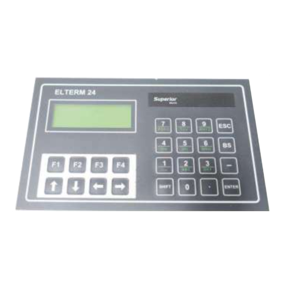
- Page 1 INSTALLATION OPERATING INSTRUCTIONS for the ELTERM 24 REMOTE OPERATOR PANEL...
-
Page 2: Table Of Contents
SECTION 4: SPECIFICATIONS ........... 10 Mechanical Specifications ........10 Electrical Specifications ........10 Environmental Specifications ......10 SECTION 5: ELTERM 24 TRANSMIT CHARACTER CODES..10 SECTION 6: EXPANDED SEBASIC COMMANDS ...... 11 SECTION 7: PROGRAMMING THE CONTROL......13 APPENDIX A: PROGRAMMING ROUTINES ....... 14 JOG Routine .............. -
Page 3: Section 1: Introduction
This manual is an installation and operating guide to the ELTERM 24 Operator Interface panel. Section 1 gives an overview of the panel and its features. -
Page 4: Product Features
ELTERM 24 back to the terminal for display. The ELTERM 24 also has a key repeat feature which can not be disengaged. When a key is pressed, the character is transmitted, then after a delay of about 0.5 seconds, if the key is still depressed, the same character is re-transmitted... -
Page 5: Section 2: Express Start Up Procedure
Program the control to accept and display keypresses from the terminal. Refer to Sections 6, 7 and Appendix A. Install/mount the ELTERM 24 and power supply. See Section 3.1 for panel cutout and mounting information. Connect the AC power source to the AC input terminals on the power supply, see Section 3.2 for connections. -
Page 6: Section 3: Installation Guidelines
The terminal is mounted by inserting it into a panel cutout then using the sup- plied mounting brackets and gasket to keep it in place. Figure 3.1a, ELTERM 24 Mounting Diagram When selecting a mounting location, it is important to leave at least two inches (51mm) of space around the top, bottom and sides of the unit to allow proper airflow for cooling. - Page 7 Dimensions, inches (mm) Mounting Plate 0.06 (1.5) - 0.1 (2.5) Thick Figure 3.1b, ELTERM 24 Panel Cutout Diagram Power Supply The 24VDC switching power supply can either be mounted using a standard DIN rail, 1.39" (35.3mm) wide, or panel mounted using the mounting holes provided.
-
Page 8: Connection Diagrams
3.2 CONNECTION DIAGRAMS Figures 3.3a - 3.3c show connections between the ELTERM 24 and a control. Refer to the figure for the applicable control. Power connections are also provided. "G;"!H98= **8???%@.AB#.&CD@.E.25F&B0 ;78: < ;789 !789 > !78: &I&&&&&&&&&(:&J:8=(%#K !SRR&/3FE,&4011,4305 &=&&&&&&&&&(9&J#0LL01K * 120 ohm termination B0M,5&*D66EFN&BA+&88OP8Q9??R... - Page 9 POWER SUPPLY CONNECTIONS The dc output power is connected to pins 6 (V+) and 4 (V-). Figure 3.4 provides dc power connections to the ELTERM 24 terminal from the 24VDC switching power supply (P/N 227928-001) and AC power connections to the power supply.
-
Page 10: Section 4: Specifications
Altitude 6,562 feet (2000 m) max 6,562 feet (2000 m) max SECTION 5: ELTERM 24 TRANSMIT CHARACTER CODES The following table lists the keys on the operator interface panel and the corre- sponding ASCII code which will be transmitted to the control. -
Page 11: Section 6: Expanded Sebasic Commands
SECTION 6: EXPANDED SEBASIC COMMANDS The commands listed below can be used when programming one of the fol- ® lowing SLO-SYN controllers: MX2000 SS2000D3i SS2000D6i SS2000PCi EXPANDED SEBASIC CONTROL COMMANDS COMMAND DESCRIPTION Cursor_ON Make cursor visible Cursor_OFF Make cursor invisible CLRSCRN Clear screen and home cursor CLRLINE... - Page 12 CLRLINE Action: Clears the current line and positions the cursor at the end of that line. Program Syntax: CLRLINE (line#) Remarks: The specified line will be cleared (erased) with the cursor positioned to the end of that line. Example: CLRLINE 3 Clears all characters on line 3 of the display and positions the cursor at the end of line 3.
-
Page 13: Section 7: Programming The Control
"Include" File- ELTERM24.INC Define statements allow the programmer to substitute keywords in place of ELTERM 24 escape codes. These define statements, listed below, have been provided in the "Include" file named ELTERM24.INC on the 3.5" disk supplied with the unit . To use the Include file perform the following steps: ®... -
Page 14: Appendix A: Programming Routines
APPENDIX A: PROGRAMMING ROUTINES The following routines have been provided on the enclosed 3.5" floppy disk. Jog Routine - Jogrtn.txt ' The following subroutine will Jog the motor. This subroutine can be ' incorporated into a program, once a certain key is pressed, this ' subroutine can be called on to jog the motor. -
Page 15: Getvalue Routine
' Resets NewValue$ to zero Keypress=INCHAR(2) ' Continuously loops until a key is LOOP WHILE Keypress=0 ' pressed on the ELTERM 24 Y=INSTR(NewValue$,".") ' Prevent the user from entering IF Keypress=46 AND Y<>0 THEN ' more than one decimal point. - Page 16 Edit Routine - Editrtn.txt ' This is a sample edit subroutine for any user defined function that requires ' data entry such as Distance or Speed. This subroutine can be used as a ' guide for writing a user specific subroutine. This subroutine calls out for ' another subroutine called "GetValue", hence the two should be used ' together.
-
Page 17: Edit Routine
Sample Program - Eltrmsmp.tsk #INCLUDE C:\MCPI\Elterm24.inc ' The INCLUDE statement allows the user to use the SE BASIC ' control commands for the ELTERM 24. When using the #INCLUDE ' command, the user must specify the location of the Elterm24.inc file. INTEGER... - Page 18 SAMPLE PROGRAM - Eltrmsmp.tsk (Cont.) GOSUB Menu_Display Keypress=INCHAR(2) ' Continuously loops until a key is LOOP WHILE Keypress=0 ' pressed on the ELTERM 24 IF Keypress=65 THEN GOSUB Get_Distance ' F1 Key IF Keypress=66 THEN GOSUB Get_Speed ' F2 Key...
-
Page 19: Sample Program
SAMPLE PROGRAM - Eltrmsmp.tsk (Cont.) IF keypress<>27 THEN ' Repeat until ESC key GOTO Get_Distance ' is pressed Distance=value RETURN Get_Speed: ' Actual Speed CLRSCRN DISP 1,8,"SPEED" DISP 2,4,"in RPM= " DISP 4,1,"ESC-Exit ENTER-Edit" fmt$="###.0" min=0.0 max=999.0 Value=motorSpeed row=2 col=11 LOCATE row,col ' LOCATE sets the position of the cursor PRINT USING#2,fmt$,Value... - Page 20 SAMPLE PROGRAM - Eltrmsmp.tsk (Cont.) PRINT USING#2,fmt$,Value ' Prints initial number Keypress=INCHAR(2) LOOP WHILE Keypress=0 IF Keypress=13 THEN CLRLINE 3 CLRLINE 4 DISP 4,5,"Edit Value" GOSUB GetValue END IF IF keypress<>27 THEN GOTO Get_Repeat repeat=value RETURN Execute: ' This section executes all of ACCEL=50 ' the parameters DECEL=50...
- Page 21 NewValue$="" ' Resets NewValue$ to zero Keypress=INCHAR(2) ' Continuously loops until a key is LOOP WHILE Keypress=0 ' pressed on the ELTERM 24 Y=INSTR(NewValue$,".") ' Prevent the user from entering IF Keypress=46 AND Y<>0 THEN Keypress=9999 ' more than one decimal point.
- Page 22 ' semicolon is used to supress the carriage return and line feed that the ' controller automatically appends to a PRINT command. The semicolon ' is also used to structure the various codes sent to the Elterm 24 panel. '***************************************************************************** ' The MX2000, TDC, DXi, and PCi have two com ports for serial communica- ' tion with external devices.
- Page 23 "INCLUDE" File - Elterm24.inc (Cont.) '******************************************************************************* ' CLRSCRN Home the cursor and clear the entire screen ' CLRLINE line# Clear the specified line ' LOCATE Move the cursor to @1(row),@2(col). ' LOCATE 2,7 Move the cursor to row 2 column 7. 'DISP Move the cursor to @1(row),@2(col)and display @3(value).
- Page 24 WARRANTY AND LIMITATION OF LIABILITY Superior Electric (the "Company"), Bristol, Connecticut, warrants to the first end user purchaser (the "purchaser") of equipment manufactured by the Company that such equipment, if new, unused and in original unopened cartons at the time...
Need help?
Do you have a question about the ELTERM 24 and is the answer not in the manual?
Questions and answers