Table of Contents
Advertisement
Quick Links
Advertisement
Table of Contents

Related Manuals for Sentinel SCU

Summary of Contents for Sentinel SCU
- Page 1 Sentinel Corrosion Monitor SCU 04/2019 INSTRUCTION MANUAL...
-
Page 2: Table Of Contents
■ TABLE OF CONTENTS LIST WITH ABBREVIATIONS SYMBOLS GENERAL DESCRIPTION CONTENTS IN THE PACKAGE APPLICATIONS INSTALLATION ACTIVATION OPERATION / USE READING REPLACEMENT DISMANTLING REMARK TECHNICAL DATA 13.1 FUNCTIONAL 13.2 MAINS ADAPTER 13.3 SENSOR 13.4 DIMENSIONS / WEIGHT ACCESSORIES 14.1 USB CABLE 14.2 RETRACTOR DECLARATION OF CONFORMITY... -
Page 3: List With Abbreviations
■ 1 LIST WITH ABBREVIATIONS HVAC Heating, Ventilation, Air-conditioning and Cooling Universal Serial Bus Light Emitting Diode Personal Computer Volts Alternating Current Volts Direct Current (m)A (Milli)amperes Millimetre European Conformity (in accordance with the European legislation) Electromagnetic Compatibility RoHS Restriction of Hazardous Substances Radius of Curvature Hertz Watt... -
Page 4: General Description
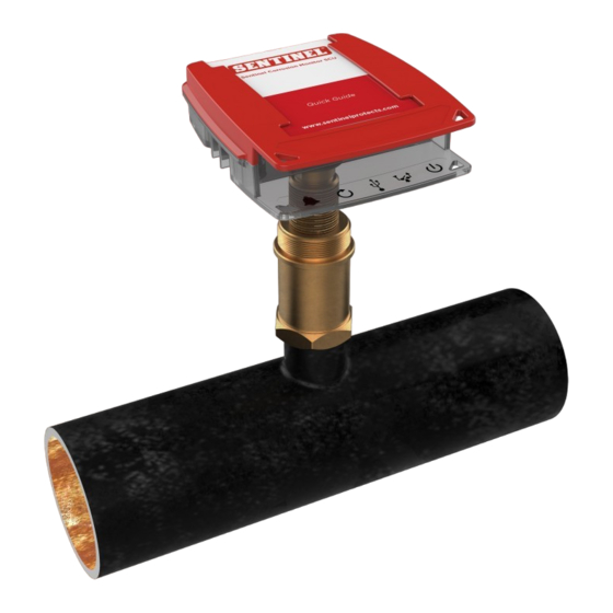
■ 3 GENERAL DESCRIPTION Sentinel Corrosion Monitor SCU is a patented measuring instrument that monitors the durability of your heating system in a reliable manner by providing timely warning of internal corrosion (or the formation of rust), and also of the particularly harmful effects that may be caused by such corrosion. -
Page 5: Contents In The Package
■ 4 CONTENTS IN THE PACKAGE • Probe with protective cap • Threaded connection • Data logger + Quick Guide • Mains adapter • 2x Tie wraps (colson strips) • Instruction Manual • Assembly guide... -
Page 6: Applications
■ 5 APPLICATIONS Sentinel Corrosion Monitor SCU is a corrosion sensor for water-based thermal systems. Studies on corrosion processes in heating systems reveal that corrosion is a complex phenomenon that is affected by many factors. The presence of oxygen in the system water is the main cause of general corrosion in a system. -
Page 7: Installation
■ 6 INSTALLATION PREPARATION The sensor is should be installed in the return section of the system, at a location with adequate flow. The tip of the probe must be placed entirely in the flow. The installation location must be free of pressure during the initial installation. - Page 8 Major boiler manufacturers recommend that once cleaned, commercial heating and closed cooling systems should be dosed with Sentinel X100 Inhibitor. Prior to adding X100, the system should be cleaned with either X400 High Performance Cleaner or X800 Fast Acting Cleaner.
- Page 9 2. Remove the protective cap from the probe. (Fig. 4) (Fig. 4) CAUTION! The probe tip should not be damaged. 3. Measure the mounting depth as shown in Fig. 5. Mark this distance on the probe. (Fig. 5) +/- 5mm CAUTION! The probe tip must be well within the flow.
- Page 10 CAUTION! Do not use sealant (flax, Loctite, etc.). The double O-rings of the probe are an effective seal. (Fig. 6) The screw thread serves to ensure that the correct mounting depth for the sensor is reached. The screw thread must never be damaged. Do not scratch! (Fig.
-
Page 11: Activation
■ 7 ACTIVATION CAUTION! The activation of the monitor takes place as follows: - in a new system: before the flushing/initial filling with water; - in an existing system: during assembly. Plug the mains adapter in the nearest socket and connect the data logger to the power supply. - Page 12 2. Secure the cable with the provided strain relief (labyrinth or tie wrap), and lay the cable in a loop to prevent dripping or splashing water from reaching the connector along the cable. (Fig. 10) (Fig. 10) From now on, the sensor LED will blink green every 2 seconds. The corrosion LED lights green and will blink off every 8 seconds.
-
Page 13: Operation / Use
Setting the limit value for the annual corrosion rate. The limit value is pre-set to 24 μm per year. This value can be adjusted by means of the dashboard software (see Chapter 9). ■ 8 OPERATION / USE MINI-USB (power/data) DATA LOGGER CORROSION SENSOR LED... -
Page 14: Reading
2. The ‘ALARM IGNORE’ button deactivates the alarm for 3 days. 3. The ‘MINI-USB’ output has two functions: - standard: connecting the data logger with the mains by means of a USB mains adapter; - exception: downloading the measuring data (see Chapter 9) using a USB/mini-USB data cable (see Chapter 14). -
Page 15: Replacement
■ 10 REPLACEMENT If a fault occurs, or when the probe tip has degraded, the probe must be replaced. PRESSURELESS REMOVAL OF THE OLD PROBE In the absence of pressure, the old probe can simply be unscrewed, i.e. the reverse of screwing it in during the initial assembly (see chapter 6, Installation). -
Page 16: Remark
■ 12 REMARK The corrosion monitor will stop measuring when the power supply cable is removed. The previously recorded data will be retained. When the power cable is reconnected, the measurements simply continue. ■ 13 TECHNICAL DATA 13.1 FUNCTIONAL • Sensor for continuous monitoring and signalling if there is a risk of excessive corrosion •... -
Page 17: Sensor
13.3 SENSOR (LOGGER AND PROBE) • Power supply voltage: 5 VDC (mini-USB) • Power consumption: Average consumption: 29 mA (including relay) Peak consumption (during measurements): 78 mA (including relay) • Relay output to break an external circuit, nominal 24 VDC/VAC, 100 mA (max. 48 VDC/VAC, 2A, 60W) •... -
Page 18: Accessories
■ 14 ACCESSORIES 14.1 USB CABLE A standard data cable USB/mini-USB is used to read the data logger (not included in the package but commercially available). 14.2 RETRACTOR The Retractor is used to replace the probe under pressure. See the Retractor manual. - Page 20 If a problem occurs, please contact Sentinel. www.sentinelprotects.com Tel +44 (0) 1928 704 330...
Need help?
Do you have a question about the SCU and is the answer not in the manual?
Questions and answers