Table of Contents
Advertisement
Quick Links
INSTRUCTION MANUAL
2240 PROcheck
Fumigation Monitor
Revision March 2022
Subject to change without notice
All rights reserved
No part of this publication may be reproduced or modified
in any form or by any means without prior permission of
ppm Messtechnik GmbH
Jahnstrasse 12 – 85661 Forstinning – Germany
www.ppm-mt.com
Advertisement
Table of Contents

Summary of Contents for PPM 2240 PROcheck
- Page 1 INSTRUCTION MANUAL 2240 PROcheck Fumigation Monitor Revision March 2022 Subject to change without notice All rights reserved No part of this publication may be reproduced or modified in any form or by any means without prior permission of ppm Messtechnik GmbH Jahnstrasse 12 –...
- Page 2 Revision history Revision 1. 4 September 2010 Software amendments concerning USB records- Error handling extended Revision 2 . 0 March 2011 GSM modem option added Software amendments Printer option removed - option obsolete Revision 2 . 1 March 2022 Updated address 4-20mA additional info Obsolete details removed UART-option removed...
-
Page 3: Table Of Contents
TABLE OF CONTENTS TABLE OF CONTENTS......................3 1. General Instructions......................1 1.1 Indications...............................1 1.2 Safety Precautions and Important Instructions....................2 1.3 Transportation / Storage / Unpacking......................2 2. Description of Gas Monitor....................3 2.1 Instrument layout.............................3 2.1.1 Front view..............................3 2.1.2 Rear View..............................4 2.2 Description of function............................5 2.2.1 Description of sensor function.........................5 2.2.2 Description of equipment function......................6 2.3 Manufacturer-based configuration........................8... - Page 4 1. Installation site..............................1 2. Electric connection............................1 3. Sample gas connection............................2 4. Interface Cable..............................3 A1: Description of Interface 2240 PROcheck - Plant Control................4 A2: Pin Assignment of Machine-Interface Connector..................6 A3: Standard-Interface-Cable..........................7 A4: Pin Assignment of Standard-Interface-Cable....................8 A5: Consumables / Spare parts for 2240 PROcheck.....................9 Annex B: Technical Specifications GSM Modem (Option V260).........1...
-
Page 5: General Instructions
General Instructions 1.1 Indications This manual has to be read carefully before switching on the instrument. The instructions must be strictly adhered to. Non-observance of these instructions may lead to the loss of right to claim for damages or warranty! Meaning of signs used in this instruction manual: Warning Indication of particular importance... -
Page 6: Safety Precautions And Important Instructions
1.2 Safety Precautions and Important Instructions The 2240 PROcheck-Analyzer is designed for monitoring, displaying, and logging the levels of a certain compound (gas). The analyzer is not intended to be a safety monitor. The 2240 PROcheck-analyzer is not designed for use in potentially explosive environments. -
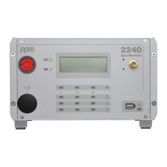
Page 7: Description Of Gas Monitor
Description of Gas Monitor 2.1 Instrument layout 2.1.1 Front view Fig. 1 Front View mains switch cover of activated carbon filter device status display LC-Display measurement channel status display push buttons (behind front panel) for instrument setup interface USB-Stick (optional) GSM-Antenna connector (optional) -
Page 8: Rear View
2.1.2 Rear View Fig. 2 Rear View 1 CPU-Module 8 Power supply module 2 Analog output (optional) 9 Service interface connector 3 Reset-Button 10 Gas outlet 4 Sensor-Module 11 Gas inlets (1...3) 5 Hose S/I – Sensor 12 SUB-D connector control interface 6 Sampling / Interface module (S/I) 13 Mains power connector 7 Hose S/I –... -
Page 9: Description Of Function
2.2 Description of function 2.2.1 Description of sensor function In Gas Monitors 2240 PROcheck a sensor is being used which operates on the principle of Infrared - NDIR. By means of which the physical quality of many gases to react to... -
Page 10: Description Of Equipment Function
2.2.2 Description of equipment function The devices of the type 2240 PROcheck are primarily intended for measurement of gas concentrations in fumigation processes. They are equipped with 3 measuring gas connections, which can be selected either by the instrument software automatically or by an external controller (Plant- or machine-control). - Page 11 Setting NO: In this setting, the contacts of the pre- and main-alarm are closed in case of exceeded thresholds. Measured LED- Contact Contact concentration level Light MOK(1..3)V MOK(1..3)H Value < Pre-alarm and open open Value < Main-alarm Value > Pre-alarm close open Value >...
-
Page 12: Manufacturer-Based Configuration
Alarm thresholds (in ppm) Operating mode (externally controlled or automatic measuring operation) Cyclic zero value measuring... -
Page 13: Technical Data
After input of date is finished, the cursor jumps to the time input. Proceed similar to date adjustment After confirmation of the minutes field, the device continues with normal start-up procedure If there are any mistakes in the adjustment of date/time, please repeat from the beginning. -
Page 14: Mounting And Installation
Mounting and Installation 3.1 Mounting OUNTING In order to assure trouble-free functioning of the instrument, mounting it as free of vibrations as possible is of essence. The instrument should be kept at a safety distance of at least 5 cm away from all surrounding walls to ensure free airflow for cooling of the equipment (see also chapter 3.2.2 for reference). - Page 15 AMPLE ONNECTIONS Sample gas connections The sample gas inlet and outlet of 2240 PROcheck are shown in Chapter 2.1.2, fig. 2, items 10 and 11. The sample gas inlets can be equipped with gas tubes of length up to 100 meters without disturbance of the instruments function. On the sample gas outlet also tubes of length up to 100 meters can be connected.
-
Page 16: Start-Up
Start-up Before connecting the instrument to the mains, make sure that supply voltage strictly corresponds to the requirements detailed in Chapter 3.2.2 Before starting-up the instrument, remove dust seals from the measuring gas inlets and outlets. Also check the existence of the zero gas filter. -
Page 17: Warm-Up Period
5.2 Warm-up period The measuring chamber of the sensor is being heated up until 50°C (122°F) have been reached. This will take approximately 3 minutes at an ambient temperature of 20°C (68°F). The actually prevailing temperature inside the measuring chamber will be displayed in °C. A progress bar shows the percentage of completion. - Page 18 (caused e.g. by a contaminated measuring chamber or by leaks etc.) the number of previous measured values will be reset to zero. 2240 PROcheck will then renew its effort for zero adjustment. If after 50 attempts no consecutive values prove to be correct, the instrument will stop zero adjustment and indicate a failure (see Chapter 6).
-
Page 19: Automatic Measurement Operation
ANUAL DJUSTMENT In those cases where 2240 PROcheck has been in operation over a period of several days without interruption a manual zero adjustment is recommended. The user may trigger such manual zero adjustment by pressing the push- button ”Reset” on the rear front plate of the CPU- Module (see fig. -
Page 20: Externally Controlled Measurement Operation
No measuring is made. In this mode 2240 PROcheck is expecting a request for measurement to be made. By means of the standard machine interface that request will be sent to the instrument by the external control using the signal MRQ(1..3),... -
Page 21: Measurement Process
1. Measurement results are shown in g/m³ or g/m (only in this example including ppm). If the symbol “<”precedes the measured value, the real measured value lies below the indicated value. On the other hand, if the symbol “>” should appear, the real value is above the over-all measurement range. - Page 22 1013 mbar (14.69 psi) by factory setting. Other reference temperatures and -pressures may be preset in the factory. The actual atmospheric pressure on site is being be measured in 2240 PROcheck and used for normalization of the measured values. The sample gas inside the measuring chamber is being kept at a constant temperature of 50°C...
- Page 23 2240 measuring sequence (Setting “NC”, see chapter 2.2.2) *** Eval. allowance depending on software version CRON = Machine control ON MRQ x = Measuring request on channel x [x=1..3] MOK x H = Contact “Mainalarm” for channel x MOK x V = Contact “Prealarm” for channel x Fig.
-
Page 24: Operational Failures
Operational Failures 6.1 Messages on instrument display Messages about errors are shown on the LCD-Display. Simultaneously the contact PMSR (instrument ready for measurement) on the machine-interface (see also Annex A, fig. A2 and A5) is opened and the contact ALARM will be closed. The alarm may be acknowledged via the input AQUIT (quit alarm, machine control) or it will come off after 1 minute automatically. -
Page 25: Failure Messages
AILURES 6.1.2 Failure messages Failure messages are indicating (with acoustic alarm and blinking failure-indicating lamp) that a direct return to normal operation of the instrument is not possible. The instrument must be switched off. After successful elimination of cause for failure or breakdown instrument may be switched on again for normal start-up procedure. - Page 26 "Operating temperature too low“ Explanation: Ambient temperature lower than 5°C resp. 41°F Probable causes: - Instrument or ambient temperature is to low (outside of the operating parameters). Corrective action: - At occurrence of this error message, operator in charge should at first check if external influences are causing this critical situation, and if applicable, eliminate those negative influ- ences.
- Page 27 "RTC“ Servicing required. Send instrument for repair “AD-converter“ Servicing required. Send instrument for repair "EEPROM" Servicing required. Send instrument for repair "CFG“ Probable causes: - Defect in data-/program - memory or manipulated data Corrective action: - Servicing required. Send instrument for repair “USB-Stick“–...
-
Page 28: Communication Problems Between Instrument And Plant Control
6.2 Communication problems between instrument and plant control Further more some malfunctions are listed which may occur during communication between plant control and the instrument. 6.2.1 Errors caused by plant control MRQ(1..3)-Signal not constant during request for measurement If significant voltage breakdowns (longer than 50 ms) occur, unintentional switch-over to a non-selected channel may hap- pen. -
Page 29: Error On Interface Cable
6.2.2 Error on interface cable No reaction of instrument Broken wires on interface cable or on plug 6.2.3 Error on Gas Monitor - interface module (MG-IF) No reaction of instrument on request for channel change If the instrument does not change measuring channels, although the control signals MRQ(1..3) and CRON have correctly been issued at the plant control side, at first the interface cable has to be inspected for defects (broken wires or bad contacts). -
Page 30: Maintenance
Maintenance 7.1 General hints The instrument has been designed for optimum maintainability. A skilled user may perform all conditioning maintenance work himself if required. LEANING The instrument housing may be cleaned with a smooth cloth which has been wetted with water and only a few drops of cleansing agent. Never use organic solvents (e.g. - Page 31 Insert the supplied filter-exchange tool into the opening. Turn it carefully counterclockwise until the filter becomes loose. Now unscrew filter from its socket by turning tool counterclockwise. Fig. 7 thread rubber gasket filter exchange tool Insert new filter into filter-exchange tool. Make sure that the rubber gasket (fig. 7, item 2) of the filter cartridge is in place.
-
Page 32: Exchange Of Sample Gas Filters (Particle Filter)
In order to avoid contamination of valves, of sample gas tubing, and of the measuring cell, the instrument must exclusively be operated using genuine particle filters supplied by ppm-mt! When changing sample gas filters, proceed as follows: In order to avoid contamination of sample- gas tubing during changing of filters, switch off instrument or pull off suction hose at rear side of instrument. -
Page 33: Calibration Of Instrument
The instrument-integrated functions concerning avoidance of zero- drift are described in chapter 5.3 of this instruction manual. The possibility for re-calibration of the Gas Monitor 2240 PROcheck is conventionally included in the scope of functions of every software version. For reference see separate calibration instructions for service personal. -
Page 34: Options
Options 8.1 Analog-outputs 8.1.1 Options V218 - analog recorder output 4-20mA When option V218 is installed, 2240 PROcheck is equipped with a galvanic separated current output. Resolution of the output current is dependent on sensor type installed and on the preset spread. During warm-up period and zero adjustment the recorder output is set to 4mA. -
Page 35: Option V220 - Analog Recorder Output 0-10V
8.1.2 Option V220 - analog recorder output 0-10V When option V220 is installed, 2240 PROcheck will be equipped with a galvanic separated voltage output. The resolution of the output voltage is depending on sensor types in- stalled and on the preset spread. During warm-up time and zero point measuring the recorder output is set to 0 Volt. -
Page 36: Option V253 - External Memory (Usb-Stick)
Please refer to Annex A, Chapter 3 8.3 Option V253 - External Memory (USB-Stick) With option V253 it is possible to store average values permanently. As storage medium a commercial USB-Stick is used. The maximum number of recordable average values depends on the capacity of the USB-Stick used: with a capacity of 256 Mbytes approx. - Page 37 CRLF (Date;Time;Zone1;Zone2;Zone3;Patm;tBOX;C;E;SN; CRLF) where Patm is atmospheric pressure [mbar], tBox is the instruments temperature [°C], C is a code for measurement unit [ppm=1, mg/m =2], E is an Error Code, SN is the instruments serial number. The error code is masked by ASCII code, starting with 65, that is the 'A'.
-
Page 38: Readout And Erasure Of Usb-Stick
Error codes, translation A: 'Pneumatic System' K: 'EEPROM' B: 'Infrared Source' L: 'Error CFG-Data' C: 'Chopper Motor' M: - not used - D: 'Sensor Heater' N: 'Sys.in.Conf.Mode' E: 'Zero Setting' O: 'USB-Stick Fault' F: 'Err Factory Cal.' P: 'No USB-Stick' G: 'Secondary Signal' Q: - not used H: 'RTC'... -
Page 39: Option V260 - Internal Gsm Modem
Hand-tighten the mounting thread and put the antenna in an upright position. WARNING! STRONG RF FIELD! During operation of the 2240 PROcheck monitor always keep a minimum distance of 25cm (10 inch) from the antenna to your body or the bodies of other persons! Non-observance of these instructions can result in personal injury. -
Page 40: Operating Frequencies
In general this function is activated. 8.4.4 Operation After POWER ON of the 2240 PROcheck monitor the modem attempts to set up a permanent connection to the www.ppm-log.com website. After the stabilization phase of the sensor temperature a message is displayed informing the user about the network strength (if network is available). -
Page 41: Annex A: Installation
Annex A: Installation Installation site. In order to warrant a trouble-free operation of the Gas Monitor 2240 PROcheck the equipment should be installed in a vibration-free installation site. The installation location is to be selected in such a manner that the in- strument may be operated and read with ease. -
Page 42: Sample Gas Connection
Sample gas connection Since pressure differences between sample gas- inlet and -outlet in- fluence the measurement result and if exceeding differential pressure of 50 mbar (0.7 psi) they might even damage the sensing detector, it is essential that gas samples tapped from the plant are returned to the plant through a port very close to the suction point! The sample-gas feed hoses must be provided with a dust filter version 2 (see also chapters 7.3).The filters must correspond to the requirements... -
Page 43: Interface Cable
For protection of measuring hoses and of measuring chamber please use genuine particle filters supplied by ppm All hoses should be made of PTFE (Teflon) or FEP in order to avoid adsorption which may cause faulty measurement results. Do NOT use Nylon- or Silicon - hoses by any means! -
Page 44: A1: Description Of Interface 2240 Procheck - Plant Control
A1: Description of Interface 2240 PROcheck - Plant Control Signals from Plant Control to 2240 PROcheck: Description Code 24 V to Pin GND to Action 2240 PROcheck Signal Pin No. Plant ON CRON Request for measurement will be accepted if ready... - Page 45 The voltage on CRON, MRQ(1..3) and AQUIT may be 24 V DC as well as 24 V AC. Max. admissible load at output contact: 48 V , 0,3 A An alarm indicated at channel-change will be quit by 2240 PROcheck automati- cally after 1 minute: Pins 2+14 open...
-
Page 46: A2: Pin Assignment Of Machine-Interface Connector
A2: Pin Assignment of Machine-Interface Connector Fig. A1 output of machine control, input to 2240 PROcheck 24 V DC or 24 V AC Pins 11, 12, 13, 23, 24 against GND, Pin 10 output of 2240 PROcheck, input to machine control... -
Page 47: A3: Standard-Interface-Cable
A3: Standard-Interface-Cable (Example) Fig. A2 connector, female, series sub-d, 25 pins connecting cable, 16 wires (LiYCY 0.34 mm²) core end sleeve shrinking hose sleeve... -
Page 48: A4: Pin Assignment Of Standard-Interface-Cable
I/F cable l = 5000 mm, with 200 mm free cable endings soldering point protected by shrinking hose sleeve output of machine control, input to 2240 PROcheck 24 V DC or 24 V AC output of 2240 PROcheck, input to machine control potential free contacts contact load max. -
Page 49: A5: Consumables / Spare Parts For 2240 Procheck
A5: Consumables / Spare parts for 2240 PROcheck Order code: Description: G03328 Particle filter 2 with 2 fittings (4mm / 6mm) G01538 Activated carbon filter G03508 Switch-Box (for 3-channel instruments without ext. control) -
Page 50: Annex B: Technical Specifications Gsm Modem (Option V260)
Annex B: Technical Specifications GSM Modem (Option V260) Indication of restriction in use: The use of this equipment requires a minimum distance from the body (25 cm or 10 inch). Safety recommendations The use of this product may be dangerous and has to be avoided in the following areas: Where it can interfere with other electronic devices in environments such as hospitals, airports, aircrafts, etc. -
Page 51: Declaration Of Conformity
Declaration of Conformity for Telit GC864-Quad-PYT GPRS/GSM-Modem, optionally installed in IR-Spectrometer 2240 PROcheck: We, ppm Messtechnik GmbH, Gartenweg 1a, 85614 Kirchseeon, Germany, declare that our optional accessory GPRS/GSM-Modem (Telit GC864-Quad-PYT), used in our IR-Spectrometer 2240 PROcheck, is in conformity with the appropriate standards ...
Need help?
Do you have a question about the 2240 PROcheck and is the answer not in the manual?
Questions and answers