Table of Contents
Advertisement
Quick Links
Operation Manual
Shutter Controller
Stanford Research Systems
Distribution in the UK & Ireland
Lambda Photometrics Limited
Lambda House Batford Mill
Harpenden Herts AL5 5BZ
United Kingdom
E:
info@lambdaphoto.co.uk
W: www.lambdaphoto.co.uk
T:
+44 (0)1582 764334
F:
+44 (0)1582 712084
SR470
Revision 1.0 • April 7, 2009
Advertisement
Chapters
Table of Contents

Related Manuals for Stanford Research Systems SR470

Summary of Contents for Stanford Research Systems SR470
- Page 1 Distribution in the UK & Ireland Operation Manual Lambda Photometrics Limited Lambda House Batford Mill Harpenden Herts AL5 5BZ United Kingdom info@lambdaphoto.co.uk W: www.lambdaphoto.co.uk +44 (0)1582 764334 +44 (0)1582 712084 Shutter Controller SR470 Stanford Research Systems Revision 1.0 • April 7, 2009...
- Page 2 (1) year from the date of shipment. Service For warranty service or repair, this product must be returned to a Stanford Research Systems authorized service facility. Contact Stanford Research Systems or an authorized representative before returning this product for repair.
-
Page 3: Table Of Contents
Front-Panel Operation ....1 – 2 The SR470 Rear Panel ....1 – 19 2 Remote Operation 2 –... - Page 4 Contents SR470 Shutter Controller...
-
Page 5: General Information
General Information The SR470 Shutter Controller is a flexible instrument capable of pow- ering, controlling, and providing I/O interfaces for an external SR470 Series Laser Shutter head. Shutter control modes include manual control from the front panel, control by an external TTL signal, and control by internal timing, including triggerable bursts. -
Page 6: Safety And Preparation For Use
Earth through the power-line-outlet ground. Line Fuse There are two line fuses internal to the SR470 that may not be serviced by the user. If no front panel LEDs are lit when line power is applied and the power switch is in the “on”... -
Page 7: Environment
Visible and invisible beams of light have the potential to cause serious bodily injury including blindness or death and to cause sig- nificant damage to property. While the SR470 is designed for use with laser systems, it is fully the users responsibility to ensure... -
Page 8: Symbols
General Information Symbols you may Find on SRS Products Symbol Description Alternating current Caution - risk of electric shock Frame or chassis terminal Caution - refer to accompanying documents Earth (ground) terminal Battery Fuse On (supply) Off (supply) SR470 Shutter Controller... -
Page 9: Notation
• Literal text other than command names is set as OFF. Remote command examples will all be set in monospaced font. In these examples, data sent by the host computer to the SR470 are set as straight teletype font, while responses received by the host computer from the SR470 are set as slanted teletype font. -
Page 10: Specifications
General Information Specifications Operation Shutter Type SR470 Series Laser Shutters. Shutter Output Drives one shutter. Shutter State Open or closed, controlled either manually from front-panel inputs or from external TTL input. Shutter Polarity User selectable for “normally open” or “nor- mally closed”... - Page 11 Ethernet; 10/100 Base-T ◦ ◦ Operating Temperature C to 40 C, non-condensing Power 90 VAC to 260 VAC, 47 Hz to 63 Hz 85 W max Physical Weight 6 lbs 8.25 W × 4 H × 11 D Dimensions SR470 Shutter Controller...
- Page 12 General Information SR470 Shutter Controller...
-
Page 13: Getting Started
1.2.8 Restoring factory default configuration ..1 – 18 The SR470 Rear Panel ....1 – 19 1.3.1 Power entry ....1 – 20 1.3.2... -
Page 14: Introduction To The Instrument
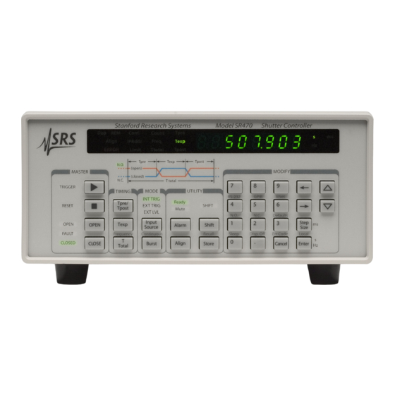
1.2 Front-Panel Operation The front panel of the SR470 (Figure 1.1) provides controls for the operator and displays the operational state of the shutter at a glance. The upper half of the panel has a multifunction numeric LED display as well as a timing diagram. - Page 15 1.2 Front-Panel Operation 1 – 3 Figure 1.1: The SR470 front panel. Numeric values are changed through the numeric keypad or the arrow keys in the “Modify” section of the front panel. To enter a value simply type the new value using the keypad and complete the entry by hitting one of the two units keys: [ms], [s], or [Hz], depending on context.
-
Page 16: Master Control And Basic Shutter Operation
The “Master” section of the front panel, located on the left hand side, contains some of the most important and frequently used controls on the SR470 . There are four keys in this section: [ ] (trigger), [ ] (reset), [OPEN] and [CLOSE]. Each of these keys has an associated indicator LED, and there is also a FAULT indicator located between the OPEN and CLOSED indicators. - Page 17 1 – 5 1.2.2.2 Shutter polarity An SR470 Series Laser Shutter head may be operated either as a nor- mally open (N.O.) or normally closed (N.C.) shutter. The normal state refers to the unasserted state of the shutter, which is (for exam- ple) the state in which the shutter idles when a trigger has not yet come.
- Page 18 1 – 6 Getting Started [ ], OPEN, or CLOSED will cause the SR470 to attempt to enable the shutter head and move it to the open or closed position as requested. If the head powers on successfully, the SR470 will display its state with either the OPEN or CLOSED indicator.
-
Page 19: Operating Modes
INT TRIG mode. 1.2.3.3 External level mode The SR470 is in the external level mode when the front panel indicator EXT LVL in the “Mode” section is illuminated. In this mode, the state of the shutter is controlled only by the level of the rear-panel TTL control input. -
Page 20: Timing And Sequences
The SR470 is capable of controlling an attached shutter head through timed sequences of operation, including triggered bursts. Sequences are allowed when the shutter is powered on and the SR470 is in the INT TRIG or EXT TRIG operating mode (§1.2.3). The se- quence does not begin until a trigger is received;... - Page 21 The postdelay follows the exposure, and is defined to begin at the moment that the shutter head begins to return to the normal state. The SR470 is able to accept new triggers after the end of the postdelay.
- Page 22 3 Hz, then the full precision of the SR470 would be dedicated to producing true 3 Hz cycles, while the delay times would be the parameters that may be truncated for display.
- Page 23 99 999 999 can be entered. As a special case of using bursts, it is also possible to configure the SR470 to cycle forever after a trigger is received. This is called infinite burst or continuous mode, and can be selected by press- ing [Shift][Continuous].
-
Page 24: Utility Functions
Getting Started 1.2.4.6 Indicators on the timing diagram The timing diagram on the front panel of the SR470 serves not only as an illustration of the different time intervals but also as an indicator. As mentioned earlier, the N.O. or N.C. label on the diagram will be lit to indicate the configured polarity of the shutter. - Page 25 The arrow keys or numeric keypad can then be used to change the value. Important note: Alternate mode settings are stored in the volatile memory of the shutter head, not in the SR470; the mode setting is lost whenever the SR470 or the shutter head is unplugged, powered down, or otherwise reset.
-
Page 26: Remote Interface Configuration
“ERROR” to the left of the numeric display. If this enunciator is lit, [Shift] [Err Code] will display the SR470 error. If the message is too long to fit on the display, the [←] and [→] keys can be used to reveal the whole message. - Page 27 SR470 . Press the [←] and [→] keys to switch between which indicate, respectively, that the RS-232 interface is at baud rate 9,600 baud or 57,600 baud. A change in this parameter will not take effect until the SR470 is power cycled or the interface is reset. 1.2.6.2 GPIB The GPIB menu can be accessed by pressing [Shift][GPIB].
- Page 28 • GPIB Address. The SR470 GPIB address may be set to any value from 0 to 30. The current value will be displayed as (for example) when the GPIB address is 8.
- Page 29 • Interface speed. The SR470 link speed may be selected to 10 Base-T, 100 Base-T, or to auto-negotiate between these speeds. Use the [←] and [→] keys to choose between...
-
Page 30: Remote Lockout And Front-Panel Operation
1.2.7 Remote lockout and front-panel operation When a host computer accesses the SR470 over one of the remote interfaces, it normally places the unit in the Remote state, where most manual input is not allowed. -
Page 31: The Sr470 Rear Panel
Figure 1.3: The SR470 rear panel. 1.3 The SR470 Rear Panel The rear panel of the SR470 (see Figure 1.3) provides input and output connectors for controlling the shutter, a TTL sync output, an alarm output, two auxiliary I/O ports, a chassis-grounded binding post, three remote interfaces, and the power entry module. -
Page 32: Power Entry
Always use an outlet which has a properly connected protective ground. 1.3.2 Chassis ground This binding post is connected to the SR470 chassis and to earth ground. 1.3.3 TTL input The primary input for the SR470 Shutter Controller is the rear-panel BNC input labeled “Control Input.”... -
Page 33: Aux I/O Ports
1.3 The SR470 Rear Panel 1 – 21 Figure 1.4: Shutter connector pinout, as seen looking into the con- nector on the rear panel. Connector Pin Description +12 V to shutter head (Coil power supply) Ground TX (Serial to shutter head) RX (Serial from shutter head) +4.5 V to shutter head (Logic power supply) -
Page 34: Sync Out
FAULT indicator is lit. The Alarm output port is always active. The polarity of the signal is such that the SR470 will no longer hold the Alarm signal at +5 VDC in the event that it loses line power. -
Page 35: Shutter Grounding Considerations
Figure 1.5: Grounding the shield of the shutter cable. 1.3.9 Shutter grounding considerations For reliable operation of a shutter head connected to the SR470 it is essential that the shield of the cable to the shutter is properly grounded. - Page 36 Getting Started The procedure for removing shield-ground connection inside the SR470 is as follows: First, turn off and unplug the unit. Wait one minute after removing power to reduce the risk due to residual volt- ages inside the instrument. To remove the top cover, first remove the four large screws from the top cover of the instrument.
-
Page 37: Remote Operation
2 Remote Operation This chapter describes operating the SR470 over its remote interfaces. In This Chapter Index of Common Commands ... . . 2 – 2 Alphabetic List of Commands ... . . 2 – 5 Introduction . -
Page 38: Index Of Common Commands
2 – 16 Auxiliary I/O BNC 2 Configuration AUXI(?) i {,j} 2 – 16 Auxiliary I/O State CHOP(?) {i} 2 – 17 Alignment Mode DISP(?) {i} 2 – 17 Display On/Off ENAB(?) {i} 2 – 17 Enable Shutter SR470 Shutter Controller... - Page 39 2 – 22 Ethernet Physical Layer Configuration IFCF(?) i{,j} 2 – 23 Interface Configuration IFRS i 2 – 23 Interface Reset LCAL 2 – 24 Go to Local LOCK? 2 – 24 Request Lock UNLK? 2 – 24 Release Lock SR470 Shutter Controller...
- Page 40 2 – 4 Remote Operation REMT 2 – 24 Go to Remote XTRM i[,j][,k ] 2 – 24 Set Interface Terminator SR470 Shutter Controller...
-
Page 41: Alphabetic List Of Commands
2 – 22 Ethernet MAC Address ENAB(?) {i} 2 – 17 Enable Shutter EPHY(?) i{,j} 2 – 22 Ethernet Physical Layer Configuration FLTS? 2 – 14 Fault Status FREQ(?) {f } 2 – 20 Frequency IFCF(?) i{,j} 2 – 23 Interface Configuration SR470 Shutter Controller... - Page 42 2 – 19 Step Size Predelay SSPS(?) {t} 2 – 19 Step Size Postdelay SSTB? 2 – 21 Shutter Status Byte SSTL(?) {t} 2 – 20 Step Size Total Delay STAT(?) {i} 2 – 18 Open/Closed State SR470 Shutter Controller...
- Page 43 2 – 20 Total Delay Time TPRE(?) {t} 2 – 20 Predelay Time TPST(?) {t} 2 – 20 Postdelay Time TRGS? 2 – 15 Trigger Status UNLK? 2 – 24 Release Lock XTRM i[,j][,k ] 2 – 24 Set Interface Terminator SR470 Shutter Controller...
-
Page 44: Introduction
2 – 8 Remote Operation 2.3 Introduction The SR470 may be remotely programmed via the GPIB interface, the RS-232 serial interface, or the LAN ethernet interface using a simple command language documented in this chapter. Any host computer interfaced to the SR470 can easily control and monitor the operation of the SR470 . - Page 45 In these examples, all data sent by the host computer to the SR470 are set as straight teletype font, while responses received the host computer from the SR470 are set as slanted teletype font. The usage examples vary with respect to set/query, and optional parameters.
-
Page 46: Command List
OPC operation complete Reserved QYE query error DDE device dependent error EXE execution error CME command error Reserved PON power-on *ESR? CR Example: The returned value of 176 (= 2 ) indicates that PON, CME, and EXE are set. SR470 Shutter Controller... - Page 47 Power-on Status Clear Set (query) the Power-on Status Clear flag {to i}. The Power-on Status Clear flag is stored in nonvolatile memory in the SR470 , and thus, maintains its value through power-cycle events. If the value of the flag is 0, then the Service Request Enable and Standard Event Status Enable Registers (*SRE, *ESE) are stored in non-volatile memory, and retain their values through power-cycle events.
- Page 48 *SRE(?) {i} Service Request Enable Set (query) the Service Request Enable register {to i}. Bits set in this register cause the SR470 to generate a service request when the corresponding bit is set in the STB register. *STB? Status Byte Query the standard IEEE 488.2 serial poll status byte.
-
Page 49: Status Reporting Commands
ORd together to set INSR BIT in the serial poll status byte. (see *STB). INSE 3 CR Example: When a trigger or an end of cycle occurs the INSR BIT of the serial poll status byte will be set. SR470 Shutter Controller... - Page 50 LERR?. The error buffer has space to store up to 20 errors. If more than 19 errors occur without being queried, the 20 error will be 254 (Too Many Errors), indicating that errors were dropped. SR470 Shutter Controller...
-
Page 51: Instrument Control Commands
If it is 1, the shutter is asserted. ASRT 0 CR Example: Place the shutter in the unasserted state. ASRT? CR Example: A return of 1 indicates that the shutter is asserted, i.e., commanded to the normal state. SR470 Shutter Controller... - Page 52 The set form sets the value applied to the BNC when it is configured for manual I/O. The query form always reads the current value of the BNC. A value of 0 indicates the BNC is logic low. A 1 indicates the BNC is logic high. SR470 Shutter Controller...
- Page 53 Mute Alarm Set (query) the mute status on the audible alarm. If i is 0 alarms are audible. If 1, alarms are muted. See §1.2.2.5 and §1.2.5.1 for more about faults and alarms on the SR470 . POLR(?) {i} Shutter Polarity Set (query) the polarity of the shutter to i.
- Page 54 The query form returns the number 2 if the shutter state is indeterminate. STAT 0 CR Example: Close the shutter. STAT? CR Example: A return of 2 indicates that the shutter 2 is in an indeterminate state. SR470 Shutter Controller...
-
Page 55: Exposure Cycle Control Commands
Set (query) the predelay step size {to t} in seconds. SSEX(?) {t} Step Size Exposure Set (query) the exposure step size {to t} in seconds. SSPS(?) {t} Step Size Postdelay Set (query) the postdelay step size {to t} in seconds. SR470 Shutter Controller... -
Page 56: Shutter Specific Commands
‘0’, ‘1’, ‘2’ or ‘3’ to the shutter. The effect of different modes is hardware dependent; please see the shutter head manual for descriptions of the available modes. The query form returns bits 12 and 13 of the shutter status byte (see SSTB). SR470 Shutter Controller... - Page 57 2.5 Command List 2 – 21 Since the mode setting is stored in the volatile memory of the shutter head, not in the SR470 , the mode setting is lost whenever the SR470 or the shutter head is reset or re-enabled. MODL? Shutter Model Query the model number for the shutter.
-
Page 58: Interface Configuration Commands
When auto-negotiation is disabled, the manual speed selection is used to configure the link. Under certain circumstances the auto-negotiation of link speed may fail. To avoid this, the SR470 defaults to manually configured 100 Base-T link speed. When setting the link speed, a value of j equal to 0 selects 10 Base-T, and a value of 1 selects 100 Base-T. - Page 59 The returned value indicates the active default gateway. IFRS i Interface Reset Reset one of the communications interfaces. The parameter i identi- fies the interface to reset: Configuration parameter RS-232 GPIB TCP/IP When an interface is reset, it is changed to its power-on state. SR470 Shutter Controller...
- Page 60 LOCK? Request Lock Request the instrument lock. The SR470 returns 1 if the lock is granted and 0 otherwise. When the lock is granted, no other instru- ment interface may alter instrument settings until the lock is released via the UNLK command or the power is cycled.
-
Page 61: Error Codes
2.6 Error Codes 2 – 25 2.6 Error Codes The SR470 contains an error buffer that stores up to 20 error codes associated with errors encountered during power-on self tests, com- mand parsing, or command execution. The ERR LED will be high- lighted when a remote command fails for any reason. -
Page 62: Query Errors
No Listener This is a communications error that occurs if the SR470 is addressed to talk on the GPIB bus, but there are no listeners. The SR470 discards any pending output. 2.6.3 Device Dependent Errors... - Page 63 Integer Overflow A parsed integer was too large to store correctly. Invalid Hexadecimal The parser expected hexadecimal characters but was unable to parse them. Syntax Error The parser detected a syntax error in the com- mand. SR470 Shutter Controller...
-
Page 64: Communication Errors
The error buffer is full. Subsequent errors have been dropped. Distribution in the UK & Ireland Lambda Photometrics Limited Lambda House Batford Mill Harpenden Herts AL5 5BZ United Kingdom Characterisation, info@lambdaphoto.co.uk Measurement & W: www.lambdaphoto.co.uk +44 (0)1582 764334 Analysis +44 (0)1582 712084 SR470 Shutter Controller...
Need help?
Do you have a question about the SR470 and is the answer not in the manual?
Questions and answers