Table of Contents
Advertisement
Quick Links
Advertisement
Table of Contents

Summary of Contents for Emcee SR 30 E
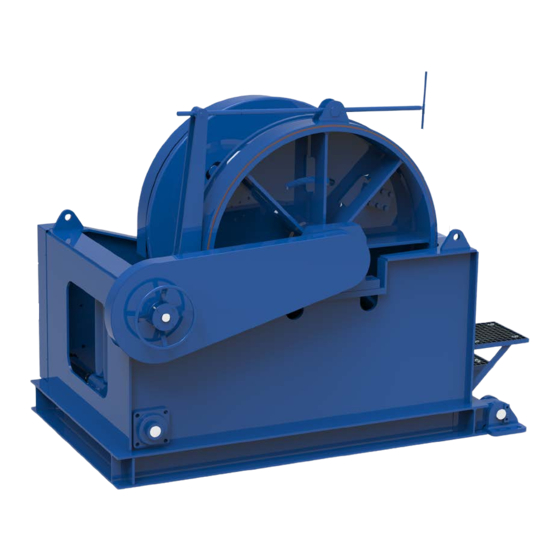
- Page 1 SR 30 E 1004156 Planetary Winches...
- Page 2 PURPOSE OF THE MANUAL This manual has been compiled by the Manufacturer to provide information on the safe transport, handling, installation, maintenance and repair of winches Failure to adhere to the information provided herein may result in risk to personal health and safety, and may incur economic damages.
- Page 3 Intellectual property Winch models, drawings and engineering are of our exclusive property. It is expressly forbidden to copy, use or hand over to third parties such information without a specific written permission. Warranty EMCÉ warrants to the original user its winches to be free of defects in material and workmanship for a period of one year from the date of purchase.
-
Page 4: Table Of Contents
CONTENT GENERAL SAFETY INSTRUCTIONS INTRODUCTION GENERAL SPECIFICATIONS OPTIONS GENERAL DESCRIPTION OF WINCHES GENERAL OPERATING PRINCIPLE DESCRIPTION OF THE ELECTRIC CIRCUIT SAFETY INFORMATION INSTALLATION INSTALLATION GEARBOX LUBRICATION ROPE START UP SEQUENCE WORKING WITH THE MACHINE START, NORMAL OPERATION and STOP INSPECTIONS TROUBLE SHOOTING MAINTENANCE LUBRICATION... -
Page 5: General Safety Instructions
1. GENERAL SAFETY INSTRUCTIONS THE WINCH MAY NOT BE USED FOR LIFTING OR MOVING PERSONS UNLESS IT IS CLASSIFIED AS A MAN RIDING WINCH. Read manual carefully before start, use or carry out any maintenance operation on the winch. This manual is issued with the scope to be a guide for the correct and safe use of the winch and for its rational maintenance. - Page 6 24. Limit switches are installed as a safety device; they are not suited to be used as positioning devices; 25. Swinging loads will significantly increase the products load and must be avoided; 26. Do not handle wires without accident prevention gloves and never try to move wires under tension; 27.
-
Page 7: Introduction
2. INTRODUCTION GENERAL Depending on the specifications EMCÉ winches are mend for lifting and/or pulling materials and/of person. The application of the winches is mentioned on the winch tag plate and the winch datasheet (see annex 1). Any other use than mentioned on the tag plate or winch datasheet excludes EMCÉ of every responsibility. SPECIFICATIONS Identification data and specifications are mentioned on the identification plate attached to the winch. - Page 8 Clutches: With a clutch the winch drum can be disengaged from the winch drive, which allows free running of the cable. The most common used is the claw clutch, which can’t be operated under load, so that the driveline must first be freed of the load (for example using a bandbrake on the winch drum).
-
Page 9: General Description Of Winches
3. GENERAL DESCRIPTION OF WINCHES GENERAL OPERATING PRINCIPLE Pulling Winch: A winch is a pulling winch when transporting a load in horizontal sense. If the wire were to be cut during operation the load would stop moving. Lifting Winch: A lifting winch is any winch which moves a load vertically during part or all of its operation. -
Page 10: Description Of The Electric Circuit
DESCRIPTION OF THE ELECTRIC CIRCUIT EMCÉ electric winches are standard supplied without controls. The required voltage can be found on the winch datasheet (see annex 1) and on the winch tag plate. The connection details of the motor can be found on the inside of the terminal box cover of the motor. - Page 11 3.3.5 Handling of the winch For lifting the winch following possibilities should be used, starting from the top. Use the lifting lugs on the frame (if applied) Use the holes in the main plate (if applied) Use a sling around the drum General Manual Electric Winches with UMPH rope-English Rev.1.1 –...
-
Page 12: Installation
4. INSTALLATION Every winch is delivered completely assembled, tested and packed on a pallet, unless specified otherwise. Check product integrity on delivery and immediately notify found damages to the transport company. For winch handling see section 3.5.6. All tenders and contracts for the performance of deliveries by us inside and outside the Netherlands are governed by the FME General Conditions for the sales and supply for mechanical and electrical industry of October 19 1998 filed under reference nr. -
Page 13: Gearbox Lubrication
Installation of gear units classified under Directive 94/9/EC Category 2D gear units must be installed in compliance with the provisions of standards EN 1127-1 and EN 50281-1-2. The installer must, therefore, be fully informed and trained for this application. The installation technician must be aware of the ATEX class of the installation area, as well as the risks associated with the presence of a potentially explosive atmosphere, with particular attention to explosion and fire hazards, and thereby adopt the necessary safety precautions. - Page 14 Other possibilities In some cases a different fastening of the rope than mentioned before is provided. In these cases the rope is fastened by means of: A hole in the drum with several fixing bolts Special wire clamps on the drum Always keep a minimum of 6 wire coils winded around the drum to warrant a safe winch load holding.
- Page 15 Failure to carry out any of the above could result in unsatisfactory and unsafe rope performance. Coils Place the coil on the ground and roll it out straight ensuring that it does not become contaminated with dust/grit, moisture or any other harmful material.
-
Page 16: Start Up Sequence
strength in order to avoid turn being transmitted from the old rope into the new rope. Alternatively a length of fibre or steel rope of adequate strength may be reeved into the system for use as a pilot/messenger line. Do not use a swivel during the installation of the rope. -
Page 17: Working With The Machine
5. WORKING WITH THE MACHINE START, NORMAL OPERATION AND STOP 5.1.1 Check list for prestart preparation 1. Perform the frequent inspection (see chapter 5.2) at the beginning of each shift. 2. Do not operate winch with any personnel near the line of force or capable of coming into contact with moving parts. - Page 18 Manual operated bandbrake (optional) The bandbrake on a winch can be used to lock the winch drum during maintenance or when the disengagement clutch on the drum is released. When a load remains in the cable after the job with the winch is finished the bandbrake should also be engaged to prevent that the loads remains on the winch drive when the winch is not in use.
-
Page 19: Inspections
On a winch without bandbrake the clutch may only be operated when there is no load in the cable. The winch drum may only be rotated manually when there is no load in the cable. Before rotating the winch drum manually, the winch must be isolated from the main supply. A dangerous occurrence is likely to occur if the motor is powered. - Page 20 reports should be dated, signed by the person who performed the inspection, and kept on file where they are readily available for review. Rope Reports Records should be maintained as part of a long-range rope inspection program. Records should include the condition of rope removed from service.
- Page 21 previous inspections. If the actual diameter of the fiber rope has decreased more than 0.4 mm (1/64inch) a thorough examination of the fiber rope should be conducted by an experienced inspector to determine the suitability of the fiber rope to remain in service. e.
- Page 22 Chemical contamination: unless the chemical is specifically known to be harmless, it should be • considered a contaminant. Texture inconsistency: soft, mushy places or hard spots (localized or over an extended area). • Age: the rope is simply worn out from use. •...
-
Page 23: Trouble Shooting
TROUBLE SHOOTING TROUBLE PROBABLE CAUSE REMEDY Product will not operate. No motor power. Check connections, circuits. Product is overloaded. Check the load. Brake is not released. Release or clean the brake. Check brake circuit. Load doesn't stop. Brake is slipping. Check air gap of brake or replace brake. -
Page 24: Maintenance
6. MAINTENANCE EMCÉ winches are engineered to a bare minimum of maintenance operations. Following maintenance operations are required for all EMCÉ winches. Specific maintenance operations are mentioned in annex 2. For installation in zones 21 and 22 the user must schedule and implement a regular cleaning program for all surfaces and recesses to avoid dust build ups of more than 5 mm in depth. -
Page 25: Slewing Gears
6.2.1 Worm-gearboxes All other worm-gearboxes are filled with E.P. (extreme pressure) rated mineral gear oil with ISO viscosity grade: ISO VG 320. Change the oil after the first 300 running hours. Subsequent oil changes are to follow at 4000 running hour intervals, or at least once a year. Oil temperatures up to 70°C are normal. -
Page 26: Annex I: Product Datasheet And Certificates
ANNEX I: PRODUCT DATASHEET AND CERTIFICATES General Manual Electric Winches with UMPH rope-English Rev.1.1 – 10-12-2014... -
Page 31: Annex Ii: Technical Information Components
ANNEX II: TECHNICAL INFORMATION COMPONENTS General Manual Electric Winches with UMPH rope-English Rev.1.1 – 10-12-2014... - Page 32 INSTALLATION, USE AND SERVICE MANUAL 300-SERIES GEARBOXES 1.0 GENERAL INFORMATION 1.1 Symbols DANGER-WARNING This symbol indicates situations of serious danger which, if ignored, may result in serious risks to the health and safety of personnel. CAUTION-ATTENTION This symbol indicates the need to adopt specific precautions to avoid risks to the health and safety of personnel and possible economic damages.
- Page 33 INSTALLATION, USE AND SERVICE MANUAL 300-SERIES GEARBOXES Use the gear unit only for the applications envisaged by the Manufacturer. Improper use can result in risks to personal health and safety and economic damages. Keep the gear unit at its maximum efficiency by following the routine maintenance schedule. Good maintenance enables the unit to operate at maximum performance over a long service life in compliance with safety regulations.
- Page 34 INSTALLATION, USE AND SERVICE MANUAL 300-SERIES GEARBOXES Brake lubrication The optional hydraulic multi-disk brakes are lubricated with the same oil as the gear unit 6.0 COMMISSIONING THE GEAR UNIT The gear unit has been factory tested by the Manufacturer. Before starting the unit, check that: ...
- Page 35 INSTALLATION, USE AND SERVICE MANUAL 300-SERIES GEARBOXES 7.2 Oil change Place an adequate container under the drain plug. Remove the filler and drain plugs and allow the oil to drain out. The oil will drain better if it is warm. Wait for a few minutes until all the oil has drained out, then screw the drain plug back on with a new gasket.
- Page 36 INSTALLATION, USE AND SERVICE MANUAL 300-SERIES GEARBOXES 9.0 TROUBLESHOOTING: The following information is intended to serve as an aid in identifying and correcting defects and faults. In some cases, such problems may be caused by the plant or machine onto which the gear unit is assembled, and hence, the cause and eventual solution can be found in the Manufacturer’s technical documentation for the machine/plant in question.
- Page 37 INSTALLATION, USE AND SERVICE MANUAL 300-SERIES GEARBOXES ANNEX 1 – LUBRICANT FILL QUANTITY: N.B. The quantities indicated are approximate only. Fill the unit according to the position of the level plug or level rod supplied with the gear unit. Technical Data 300-series gearboxes-English Rev.1.3 - 15-12-2010...
- Page 38 INSTALLATION, USE AND SERVICE MANUAL 300-SERIES GEARBOXES N.B. The quantities indicated are approximate only. Fill the unit according to the position of the level plug or level rod supplied with the gear unit. Technical Data 300-series gearboxes-English Rev.1.3 - 15-12-2010...
- Page 39 INSTALLATION, USE AND SERVICE MANUAL 300-SERIES GEARBOXES ANNEX 2 - Mounting positions Technical Data 300-series gearboxes-English Rev.1.3 - 15-12-2010...
- Page 40 INSTALLATION, USE AND SERVICE MANUAL 300-SERIES GEARBOXES ANNEX 3 - Plug positions Technical Data 300-series gearboxes-English Rev.1.3 - 15-12-2010...
- Page 41 INSTALLATION, USE AND SERVICE MANUAL 300-SERIES GEARBOXES Technical Data 300-series gearboxes-English Rev.1.3 - 15-12-2010...
- Page 42 AC INDUCTION THREE-PHASE MOTORS Rated voltage For the rated voltage of the motors, EN 60 034-1 allows a tolerance of ± 5 %. According to IEC 60038, the mains voltages may have a tolerance of ± 10 %. Therefore the motors are designed for the following rated voltage ranges (exceptions are shown in the data tables): Mains voltage to DIN IEC 38 Rated voltage range of motor 230 V ±...
- Page 43 AC INDUCTION THREE-PHASE MOTORS Installation at altitudes of more than 1000 m above sea level (see also EN 60034-1) Altitude of installation 2000 m 3000 m 4000 m At 40°C ambient temperature and thermal class B 92 % 84 % 76 % Rated output reduced to approx.
- Page 44 AC INDUCTION THREE-PHASE MOTORS Three-phase cage motors driven by frequency converters Maximum converter output voltage 500V at peak voltages Û ≤ 1460 V and du/dt ≤13 kV/us. For higher converter output voltages or stresses, a special insulation is required. With square characteristic of the load torque, motors can be driven with their rated torque. For constant torque, the rated torque of motors with internal cooling must be reduced due to reduced cooling air inlet.
- Page 45 AC INDUCTION THREE-PHASE MOTORS Used petrol or benzene in airtight tanks should be disposed of as special refuse with the marking «Petrol» or «Benzene». Afterwards, with the outer bearing cap open but the inner cap screwed on, the rotor should be turned slowly and grease pressed in through the regreasing device until approximately half the empty space between the rolling elements and the roller tracks is filled with grease.
- Page 46 AC INDUCTION THREE-PHASE MOTORS Spare parts for three-phase motors Part description Shaft protection Dust seal drive end Rotor complete End shield drive end Bearing non-drive end Bearing drive end Pre-load washer Stator frame End shield non-drive end Terminal board Fan cover Fixing screw terminal board Fixing screw fan cover Gasket terminal box...
-
Page 47: Annex Iii: Drawings & Schematics
ANNEX III: DRAWINGS & SCHEMATICS General Manual Electric Winches with UMPH rope-English Rev.1.1 – 10-12-2014... - Page 48 APPROVED REVISION DRAWN BY DESCRIPTION DATE ENGINEERING dsch 16-4-2015 FOR APPROVAL O 32(9 LAYERS) GENERAL NO TES: 1. THIS DRAWING IS SUBJECT TO FURTHER ENGINEERING DEVELOPMENT. TECHNICAL D ATA: WORKING LOAD LIMIT (W.L.L.) 1st LAYER 30.000 DRUM CABLE O Nr. OF LAYERS PIPE O PIPE LENGTH CABLE STORAGE...
- Page 53 3 x 4 0 0 V + P E 5 0 H z 3 x 4 0 0 V + P E 5 0 H z 3 x 4 0 0 V + P E 5 0 H z...
- Page 54 Col l ec t or mat eri al l i s t -det ai l Q u a n t i t y T y p e D e s c r i p t i o n M a n u f a c t u r e r...
- Page 55 Col l ec t or mat eri al l i s t -det ai l Q u a n t i t y T y p e D e s c r i p t i o n M a n u f a c t u r e r...
- Page 56 Col l ec t or mat eri al l i s t -det ai l Q u a n t i t y T y p e D e s c r i p t i o n M a n u f a c t u r e r...
- Page 57 Mat eri al -Det ai l C o m p T y p e Q u a n t i t y D e s c r i p t i o n M a n u f a c t u r e r...
- Page 58 Mat eri al -Det ai l C o m p T y p e Q u a n t i t y D e s c r i p t i o n M a n u f a c t u r e r...
- Page 59 Mat eri al -Det ai l C o m p T y p e Q u a n t i t y D e s c r i p t i o n M a n u f a c t u r e r...
- Page 60 Mat eri al -Det ai l C o m p T y p e Q u a n t i t y D e s c r i p t i o n M a n u f a c t u r e r...
- Page 61 Mat eri al -Det ai l C o m p T y p e Q u a n t i t y D e s c r i p t i o n M a n u f a c t u r e r...
- Page 62 Mat eri al -Det ai l C o m p T y p e Q u a n t i t y D e s c r i p t i o n M a n u f a c t u r e r...
- Page 63 ANNEX IV: GUIDELINES TO COMPLY WITH THE MACHINERY DIRECTIVE 2006/42/EC Rated capacity limiters: Winches with a rated capacity of 1000 kg or more shall be fitted with a rated capacity limiter in accordance with EN 14492-1 section 5.2.2.1. The rated capacity limiter shall be designed to prevent overloading of the winch. It shall also limit the forces transmitted to the supporting structure, which are to be provided by the manufacturer.
- Page 64 ANNEX V: WINCH CLASSIFICATION ACCORDING TO ISO 4301-1 Class of utilization of mechanisms Class of utilization Total duration of use (h) Remarks Irregular use 1600 3200 Regular light use 6300 Regular intermittent use 12500 Irregular intensive use 25000 50000 Intensive use 100000 Nominal load spectrum factor for mechanisms, K Nominal load spectrum...
- Page 65 Notes: General Manual Electric Winches with UMPH rope-English Rev.1.1 – 10-12-2014...
- Page 66 General Manual Electric Winches with UMPH rope-English Rev.1.1 – 10-12-2014...
Need help?
Do you have a question about the SR 30 E and is the answer not in the manual?
Questions and answers