
Summary of Contents for Tritech MicronNav 200
- Page 1 MicronNav 200 Hardware Manual MicronNav 200 System Hardware Manual 0734-SOM-00002-01 0734-SOM-00002-01 Page 1 of 27...
- Page 2 MicronNav 200 Hardware Manual © Tritech International Ltd The copyright in this document is the property of Tritech International Ltd. The document is supplied by Tritech International Ltd on the understanding that it may not be copied, used, or disclosed to others except as authorised in writing by Tritech International Ltd.
-
Page 3: Table Of Contents
Help & Support ........................4 Warning Symbols ......................5 Introduction to Tritech USBL Technology ................6 How does the Tritech USBL System Work? ..............7 What makes up a Tritech MicronNav System? ..............8 Technical Specifications ....................10 Physical and Acoustic Details ..................10 MicronNav 200 Surface Hub .................. -
Page 4: Help & Support
Under no circumstances should a product be returned that is contaminated with radioactive material. The name of the organisation which purchased the system is held on record at Tritech International Ltd and details of new software or hardware packages will be announced at regular intervals. -
Page 5: Warning Symbols
MicronNav 200 Hardware Manual Warning Symbols Throughout this manual the following symbols may be used where applicable to denote any particular hazards or areas which should be given special attention: Note This symbol highlights anything which would be of particular interest to the reader or provides extra information outside of the current topic. -
Page 6: Introduction To Tritech Usbl Technology
(responder mode) through the main port. The Responder trigger can come either from the auxiliary port on a Tritech Micron Sonar, or directly from the MicronNav 200 interface hub. Both the USBL Dunking Transducer and the Micron Modem/Micron Battery Modem can be commanded to switch from positioning mode to data transfer mode, allowing the same hardware to be used to establish an underwater acoustic communications link. -
Page 7: How Does The Tritech Usbl System Work
In addition, conventional systems have poor immunity to the continuously varying background sea noise (such as wave noise). Tritech’s Spread Spectrum technology however does not concentrate the acoustic energy in one waveband but produces a transmission which is linearly varied between 20 kHz and 28 kHz (known as a CHIRP waveform). -
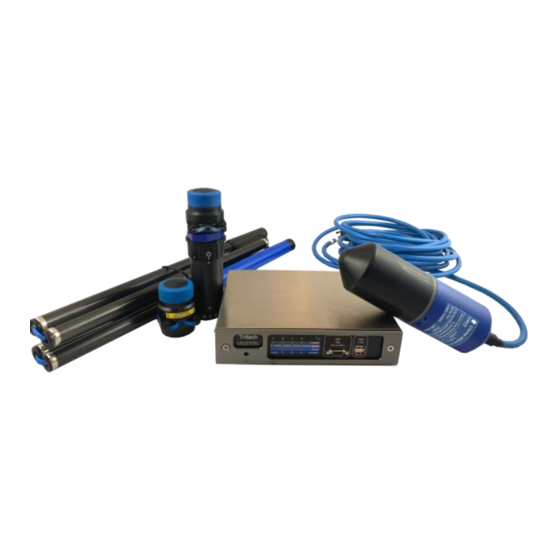
Page 8: What Makes Up A Tritech Micronnav System
MicronNav 200 Hardware Manual What makes up a Tritech MicronNav System? The standard system comprises of the following equipment: Part Number Description Image Quantity MicronNav 200 Hub This is the surface interface for the system and is connected to S11175... - Page 9 MicronNav 200 Hardware Manual Additional Equipment Part Number Description Image Quantity Battery Modem This has all the same features that a normal modem has, but S11932 with the added convenience of an internal battery. This is not part of the standard system and can be purchased separately.
-
Page 10: Technical Specifications
MicronNav 200 Hardware Manual Technical Specifications Physical and Acoustic Details System Positioning technology Ultra Short Baseline (USBL) 20 – 28kHz Frequency band Data rate 40bits/s or 100bits/s (spread spectrum) Tracking range * 500m Horizontal, 150m Vertical Range accuracy ** ±0.2m Bearing accuracy 1°... -
Page 11: Micronnav 200 Surface Hub
MicronNav 200 Hardware Manual MicronNav 200 Surface Hub All dimension shown in mm ot to scale MicronNav 200 Surface Hub Power requirement (AC or DC) 90-264 VAC (47-63Hz) or 15-36 VDC Power consumption 8.5W from either source (with no external load) Output voltage 33V (when on AC Supply), 31.5V (when on DC supply) -
Page 12: Usbl Dunking Transducer
MicronNav 200 Hardware Manual USBL Dunking Transducer USBL Transducer Transmit source level 173dB re. 1µPa at 1m Deck cable length 10m standard (20m, 50m options) Depth rating Dimensions 75 x 250mm (diameter, length) Weight in air 1.0kg Weight in water 0.1kg... -
Page 13: Battery Modem
MicronNav 200 Hardware Manual Battery Modem 0734-SOM-00002-01 Page 13 of 27... -
Page 14: Micron Modem
-10° to 35°C (operational), -20° to 50°C (storage) * Battery Modem operational temperature limited to no less than 10°C during charging or while on external power. Specification subject to change in line with Tritech’s policy of continual product development 0734-SOM-00002-01 Page 14 of 27... -
Page 15: Electrical Connections And Pin-Outs
MicronNav 200 Hardware Manual Electrical Connections and Pin-Outs MicronNav 200 Hub Ports A-C Electrical Connection DE-9 Connector Face View 0734-SOM-00002-01 Page 15 of 27... - Page 16 MicronNav 200 Hardware Manual Port D Electrical Connection Port D socket should be used with a DIN-45322 (6 pin) plug and should be wired as follows: Connector Face View AIF (ARCNET) Port Electrical Connection DA-15 AIF (ARCNET) connector, and should be wired as follows:...
-
Page 17: Tritech Micron Connector
MicronNav 200 Hardware Manual Tritech Micron Connector A Tritech Micron tail (Part Number S05975) is supplied in 1 and 2 metre lengths and should be wired as follows: Connector Face View Wire Colour Function RS485 A Yellow RS232 TX RS485 B... -
Page 18: Using The Micronnav Hub
MicronNav 200 Hardware Manual Using the MicronNav Hub Checking the MicronNav Hub Status The MicronNav Hub has been designed to act as an interface device between the surface control computer, USBL Dunking Transducer and connected subsea equipment. As such, during normal operation there is little to no onscreen notification of the MicronNav Hub status. -
Page 19: System Installation
MicronNav 200 Hardware Manual System Installation Using the MicronNav System with Tritech Sonars It is possible to operate the MicronNav with other Tritech Sonars in the same way as that detailed for the MKII/MKIII Micron. The following list provides details on MicronNav... -
Page 20: Mounting The Usbl Dunking Transducer
MicronNav 200 Hardware Manual Mounting the USBL Dunking Transducer The USBL Dunking Transducer may be secured with a 75mm diameter clamping mechanism, placed above the line shown on the Product label as below. The Clamping Point for the USBL Dunking Transducer. - Page 21 MicronNav 200 Hardware Manual The yellow line indicating the front of the USBL Dunking Transducer. Mounting Depth Mount the USBL Dunking Transducer head at least 1m to 2m below the surface of the water. Caution The USBL Dunking Transducer head is rated to a depth of 30m and must not exceed this depth.
-
Page 22: Mounting The Usbl Dunking Transducer To A Vessel
MicronNav 200 Hardware Manual Mounting the USBL Dunking Transducer to a Vessel When positioning the USBL Dunking Transducer it may be difficult to achieve the recommended 2m to 3m clearance from the vessel’s side. In this case it is recommended to lower the head deeper to ensure a clearance of 1m to 2m below the bottom of the hull. -
Page 23: System Mobilisation
MicronNav 200 Hardware Manual System Mobilisation The following assumes that the hardware and software have already been configured and tested topside. Below is a series of checklists to follow, prior to the ROV/Diver being deployed into the water. The Pre-Dive check list should be carried out to ensure maximum reliability and performance from the system. -
Page 24: Operational Checklist
MicronNav 200 Hardware Manual Operational Checklist Deploy ROV/ Diver into the water Dive to a depth 1 metre (below the USBL dunking transducer) and check position updates, move ROV/Diver, and check position trail on Genesis NAV Application screen matches ROVs... -
Page 25: Troubleshooting
Check that the power supply requirements for either the AC (Mains) or DC source have not been exceeded. If the unit still continues to be unresponsive, refer to Tritech Support for further help. The USB link between the MicronNav Hub and the PC doesn’t work. - Page 26 MicronNav 200 Hardware Manual The RAT (Remote Access Terminal) does not work. • Check that the RAT being used is labelled as a “Version S- ” RAT The MicronNav Hub unit does not support previous versions (i.e. With Trackball instead of Togglestick pointer).
- Page 27 MicronNav 200 Hardware Manual The serial port device doesn’t work in RS485 mode. • Check A and B wiring connections are correct on both ends or any interconnect cabling, and not crossed • Check that baud rates and serial setup on both the device and the PC are correct •...
Need help?
Do you have a question about the MicronNav 200 and is the answer not in the manual?
Questions and answers