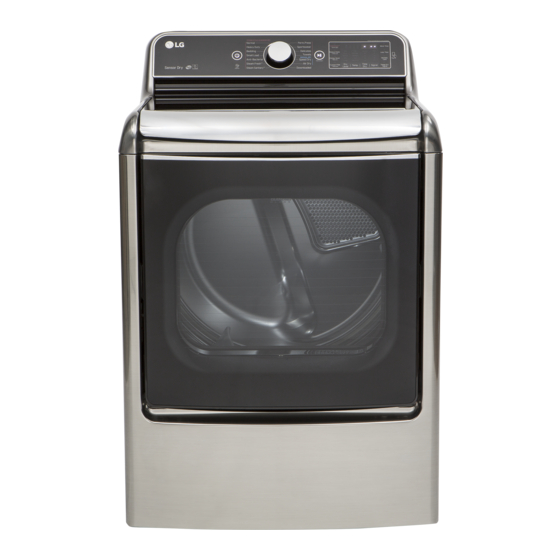
LG DLEX7700-E Service Manual
Electric & gas dryer
Hide thumbs
Also See for DLEX7700-E:
- Owner's manual (116 pages) ,
- Service manual (74 pages) ,
- Owner's manual (108 pages)
Advertisement
Quick Links
Advertisement

Related Manuals for LG DLEX7700-E


Summary of Contents for LG DLEX7700-E
- Page 1 All manuals and user guides at all-guides.com...
- Page 2 All manuals and user guides at all-guides.com...
- Page 3 All manuals and user guides at all-guides.com...
- Page 4 All manuals and user guides at all-guides.com ACCESSORIES Included accessories Optional accessory Y connector Hose Dryer rack (1 each) See page 6 of this manual for usage instruction.
- Page 5 All manuals and user guides at all-guides.com DLEX7700*E DLGX7701*E 9.0 cu.ft. Gas dryer : 156.3 Electric dryer : 152.8 29 X 31.5 X 45.1 (inch) 31 X 32.8 X 47.4 (inch)
- Page 6 All manuals and user guides at all-guides.com...
- Page 7 All manuals and user guides at all-guides.com...
- Page 8 All manuals and user guides at all-guides.com...
- Page 9 All manuals and user guides at all-guides.com...
-
Page 10: Connect Inlet Hose
All manuals and user guides at all-guides.com Connect Inlet Hose 21.8 150~800... - Page 11 All manuals and user guides at all-guides.com Mid High 10min Steam Fresh™ Adjustable Adjustable Steam High 31min Sanitary™ Antibacterial High Normal Dry Bedding Medium Normal Dry Heavy Duty High Normal Dry Perm. Press 32min Normal Dry Normal Medium 41min Normal Dry Delicates 28min Normal Dry...
- Page 12 All manuals and user guides at all-guides.com Auto reset -31°F (-35°C) Same shape as outlet thermostat. 4. LED Lamp Schematic: If the lamp is turned on It is not by connecting is normal. measured by multimeter because V is 3.2V Measure resistance of the following terminal 1) Door open...
- Page 13 All manuals and user guides at all-guides.com...
- Page 14 All manuals and user guides at all-guides.com Ω Ω Electric type 15. Inlet. valve Measure resistance of the Following terminal Left picture -.plate...
- Page 15 All manuals and user guides at all-guides.com Ω Ω Ω Ω...
- Page 16 All manuals and user guides at all-guides.com...
- Page 17 All manuals and user guides at all-guides.com TurboSteam™ helps prevent the overdrying of clothes by injecting steam during the drying process. The Steam Shield Function extends the life of clothes.
- Page 18 All manuals and user guides at all-guides.com...
- Page 19 All manuals and user guides at all-guides.com...
- Page 20 All manuals and user guides at all-guides.com...
- Page 21 All manuals and user guides at all-guides.com Damp Dry Signal Temp. Damp Dry Signal + Temp. + Power.
- Page 22 All manuals and user guides at all-guides.com ※...
- Page 23 All manuals and user guides at all-guides.com 2. Press Power and press More Time and Less Time simultaneously in 0.5 seconds. L06(Elec Type) L07(Gas Type) Main PGM Display PGM Thermistor open Thermistor shorted ELECTRIC TYPE Mist Valve on, Motor+ Heater1+Heater2 off Water Supply Valve Mist Valve GAS TYPE...
- Page 24 All manuals and user guides at all-guides.com 120V AC Electrical Supply...
- Page 25 All manuals and user guides at all-guides.com TAP RELAY 1 TAP RELAY 2 ✽ ELEC...
- Page 26 All manuals and user guides at all-guides.com ✽...
- Page 27 All manuals and user guides at all-guides.com Thermistor Test --- Measure with Power Off...
-
Page 28: Motor Test
All manuals and user guides at all-guides.com Motor Test Ω Ω Ω Ω Ω... - Page 29 All manuals and user guides at all-guides.com Moisture Sensor Moisture sensor Ω...
-
Page 30: Door Switch Test
All manuals and user guides at all-guides.com Door Switch Test Ω Ω Ω Ω... - Page 31 All manuals and user guides at all-guides.com Heater Switch Test - Electric Type Ω Ω Ω Ω Ω Ω...
- Page 32 All manuals and user guides at all-guides.com GAS Valve Test - Gas Type GAS Valve test - Gas Type Ω...
-
Page 33: Change Gas Setting (Natural Gas, Propane Gas)
All manuals and user guides at all-guides.com CHANGE GAS SETTING (NATURAL GAS, PROPANE GAS) Warning Initially, The burner is set for natural gas at the factory. The propane orifice Natural Gas mode is set. Propane Gas Orifice is on sale as a Service conversion kit is sold as a service part to autherized servicers only. - Page 34 All manuals and user guides at all-guides.com...
- Page 35 All manuals and user guides at all-guides.com PANEL REAR [ELECTRIC] 1. Remove 1 screw. 2. Pull out the cover. 3. Remove 3 screws. 4. Disassemble terminal block and wire from panel rear. PANEL REAR [ELECTRIC] 1. Remove one screw for removing safety cover.
-
Page 36: Control Panel Assembly
All manuals and user guides at all-guides.com CONTROL PANEL ASSEMBLY 1. Remove the 2 screws from the control panel. 2. Place a towel over the top cover to prevent scratch to the surface. Gently lift each corner of the back panel, then roll it forward so it rests on top of the dryer. -
Page 37: Control Panel
All manuals and user guides at all-guides.com CONTROL PANEL 1. The knob will be taken out if pulled forward. 2. Remove 7 screws from control panel assembly. 3. Separate PCB from control panel. - Page 38 All manuals and user guides at all-guides.com How to change top cover 1. Remove the 4 screws. 2. Disassemble terminal block with power cord. 3. Disassemble rear panel and both side screws.
- Page 39 All manuals and user guides at all-guides.com 4. Disassemble 2 screws on the front panel. Be careful with the marked hook not to be broken when removing the front panel. 5. Disassemble PCB cover and housing from the PCB. 6. Please push the 2 spots(hooks) by using paddle between top cover and door cabinet.
- Page 40 All manuals and user guides at all-guides.com 7. You can open the top cover. How to change lid assembly 1. Please remove the hook using a flathead screwdriver. 2. The Damper and Lid Assembly must be removed. Pull the Damper at this time. 3.
- Page 41 All manuals and user guides at all-guides.com 4. The Lid Assembly can be separated if pulled gently.
- Page 42 All manuals and user guides at all-guides.com How to Replace the inlet hose 1. The nozzle connector to the hose is disassembled while holding down the area marked. 2. Remove the 7 screws from the Cover, Rear. 3. Pull out the Tub, Rear that is hanging on a hook while lifting up.
- Page 43 All manuals and user guides at all-guides.com How to Replace the inlet hose 5. Remove the hose in generator. 6. Remove the cable tie holder in Tub, Rear. 7. Replace the hose, and assemble the cable tie holder in Tub, Rear. 8.
- Page 44 All manuals and user guides at all-guides.com How to Replace the steam harness 1. Remove the six connector in generator. 2. Remove the thermistor screw in generator. 3. Remove the steam harness cable tie holder in Tub, Rear. 4. Replace the steam harness and assemble the cable tie holder in tub rear. 5.
- Page 45 All manuals and user guides at all-guides.com How to Replace the generator and bracket 1. Remove the décor, guard screw. 2. If you are decomposing the generator and 3. Remove the bracket in generator. Tub Rear, lifting the generator on Tub Rear. 4.
- Page 46 All manuals and user guides at all-guides.com...
- Page 47 All manuals and user guides at all-guides.com Remove the Top cover. Hold the lamp in place while pressing lamp both side. Replace the new lamp.
- Page 48 All manuals and user guides at all-guides.com...
- Page 49 All manuals and user guides at all-guides.com...
- Page 50 All manuals and user guides at all-guides.com...
- Page 51 All manuals and user guides at all-guides.com Two large screws Two small screws twelve screws Hole interlock plug button ※ Φ Φ Φ Φ...
- Page 52 All manuals and user guides at all-guides.com...
- Page 53 All manuals and user guides at all-guides.com twelve screws Hole interlock plug button...
- Page 54 All manuals and user guides at all-guides.com While pushing the handle,push the button...
- Page 55 All manuals and user guides at all-guides.com THE DRYER DOOR IS VERY LARGE AND HEAVY. Failure to follow the instructions below can result in damage to the dryer, property damage or personal injury. The edges of the door cover may be sharp. Take care when handling, or wear gloves to avoid injury.
- Page 56 All manuals and user guides at all-guides.com 6. Reverse the hinge and the hinge bracket at the bottom of the cabinet. Remove the two screws from the hinge bracket at bottom right and remove the hinge bracket. Remove the lower of the two screws behind the hinge bracket. Do NOT remove the upper screw behind the hinge bracket.
- Page 57 All manuals and user guides at all-guides.com Inner Structure of Door (before reversing - right hinge swing) Top interlock buttons inner lock rods upper hinge assembly upper hinge upper hinge pivot filler top lock rod side lock rod glass Side Interlock button lower hinge filler lower...
- Page 58 All manuals and user guides at all-guides.com 15. Once the top lock rod has been removed, the hinge pivot can easily be removed from the hinge assembly on the upper left and set aside. Carefully lift the upper hinge assembly (on the left) out of the outer the hinge assembly 180 degrees and install it on the upper right side assembly.
- Page 59 All manuals and user guides at all-guides.com 18. Slide the upper lock rod left and place the top right hinge pivot in the hinge assembly. When the rod is released, it should lock the hinge pivot in place. a. Remove the screw from the lower hinge bracket (on the right) and lift the hinge bracket out.
- Page 60 All manuals and user guides at all-guides.com 22. Clean the glass on the door and door cover, if necessary. Make sure the two gray interlock buttons are properly installed and that the top and side lock rods are properly aligned where they meet. Carefully lower the door cover into place, aligning the holes in the cover with the interlock buttons on the top and the bumpers on the bottom.
- Page 61 All manuals and user guides at all-guides.com...
- Page 62 All manuals and user guides at all-guides.com...
- Page 63 All manuals and user guides at all-guides.com...
- Page 64 All manuals and user guides at all-guides.com...
- Page 65 All manuals and user guides at all-guides.com...
- Page 66 All manuals and user guides at all-guides.com...
- Page 67 All manuals and user guides at all-guides.com...
- Page 68 All manuals and user guides at all-guides.com Laundry Status(Run Cycle Again) Using LG Smart Laundry & DW application...
- Page 69 All manuals and user guides at all-guides.com...
-
Page 70: Control Panel And Plate Assembly
All manuals and user guides at all-guides.com 16-1. Control Panel and Plate Assembly A130 A700 A110 A140 A150 A120 A220 A211 A230 A570 A225 A215 A210... - Page 71 All manuals and user guides at all-guides.com 16-2-1. A850 A800 A311 A310 A610 A380 A212 A590 A390 A131 A360 A330 A315 A325 A212 A320 A314 A370 A600 A315 A360 A300 A500 A315 A530 A305 A520 A525 A540 A400 A441 A440 A410 A475 A460...
- Page 72 All manuals and user guides at all-guides.com 16-3-1. K400 K740 F200 K742 K502 K743 K505 K509 K120 K741 K720 K730 K100 K140 K250 K251 K130 K221 K336 K210 K350 K320 K335 K340 K310 K330 K250 K620 K550 K560 K610 K251 K540 K240 K530...
- Page 73 All manuals and user guides at all-guides.com MFL62119986...