
Related Manuals for Atim Cloud Wireless ACW/LW8-DIND160

Summary of Contents for Atim Cloud Wireless ACW/LW8-DIND160
- Page 1 ATIM Cloud Wireless ® Metering and Dry Contacts DINDxxx User Guide Concerned models: ACW/LW8-DIND160 ACW/SF8-DIND160 ACW/LW8-DIND80 ACW/SF8-DIND80 ACW/LW8-DIND88 ACW/SF8-DIND88 ACW/LW8-DIND44 ACW/SF8-DIND44...
-
Page 2: Table Of Contents
Table of content SOFTWARE VERSION ................................... 4 DOCUMENT VERSION HISTORY ................................4 DISCLAIMER ......................................5 TRADEMARKS AND COPYRIGHT ................................5 DECLARATION OF COMPLIANCE ................................. 5 ENVIRONMENTAL RECOMMENDATIONS ............................5 ....................................5 NVIRONMENT ....................................... 6 ADIO PRELUDE ......................................7 TECHNICAL FEATURES ..................................8 ................................... - Page 3 Pairing method setup ..................................19 Setup of the shock alarm .................................. 19 USB .................................. 19 ONFIGURATION VIA UPLINKS ON IOT NETWORKS (SIGFOX/LORAWAN) ........................... 23 ..................................... 23 EST FRAME ..................................... 23 EEP ALIVE FRAME ....................................23 TATE FRAME Digital inputs frame ..................................24 Frame of digital IN/OUT and temperature ............................
-
Page 4: Software Version
TECHNICAL SUPPORT ..................................44 Software version Product reference Product version ACW/SF8-DIND160 ACW/SF8-DIND80 ACW/SF8-DIND88 ACW/SF8-DIND44 ACW/LW8-DIND160 ACW/LW8-DIND80 ACW/LW8-DIND88 ACW/LW8-DIND44 Document version history Version Date Description Author 10/06/2017 Document creation 26/06/2017 Corrections 27/09/2017 Complete Sigfox version SF8/LW8 versions in 8 and 16 inputs... -
Page 5: Disclaimer
ATIM. Trademarks and copyright ® ® ATIM, ACW ATIM Cloud Wireless and ARM Advanced Radio Modem are registered trademarks of ATIM SARL in France. The other trademarks mentioned in this document are the property of their respective owners. -
Page 6: Radio
General hazard – Failure to follow the instructions presents a risk of equipment damage. Electrical hazard – Failure to follow the instructions presents a risk of electrocution and physical injury. WARNING: do not install this equipment near any source of heat or any source of humidity. WARNING: for your safety, it is essential that this equipment be switched off and disconnected from mains power before carrying out any technical operation on it. -
Page 7: Prelude
Prelude This guide describes the features of the ACW-DINDxxx product. It describes the characteristics of the product, explains its commissioning, its configuration, and its operation. The ACW-DINDxxx is intended to raise the digital input states (Dry contacts) on an IoT network such as Sigfox or LoRaWAN. -
Page 8: Technical Features
Technical features a. Products features Dimensions 53 x 67 x 95 mm Antenna External via SMA connector -20°C to +55°C (operation) Temperature -40°C to +70°C (storage) Mounts to DIN rail Power supply 1x power supply, 10-30 V DC Consumption 100 mA -16 configurable inputs -Change of state alerting Dry contacts Digital inputs... -
Page 9: Electrical Features
b. Electrical features Min. Type Max. Power supply (V) Condition: 60mA – Sigfox 60mA – -12V Power supply LoRaWAN -Every output is shut down Emission consumption (mA) Condition: 35 mA – Sigfox 30mA – - 24V Power supply LoRaWAN -Every output is shut down Condition: 50mA –... -
Page 10: Temperature Sensor Features
Temperature sensor features Optionally, a temperature sensor can be connected to the ACW-DINDxxx. The following ranges refer to the sensor used. Be careful, the product has a smaller operating range than the sensor (see above). Temperature Range -55°C to +125 °C Resolution 0,1°C Precision between -40°C and +80°C... -
Page 11: Casing
Casing a. Space requirements Dimensions are given in mm. ACW modems in ‘breaker’ format are attached to a DIN-rail. ACW-DINDxxx_UG_EN_V1.10... -
Page 12: Identification
b. Identification The product identifier is visible on the outer label: Product reference Product ID DIN88 Product revision number (Technical state hardware and firmware) Datamatrix DevEUI LoRaWAN Serial N° of the product ACW-DIND88 label Each product in ATIM's ACW range has a QR Code label visible either on the side or on the front of the product. This QR Code can be easily read with any 2D barcode reader app on your smartphone. -
Page 13: Set Up
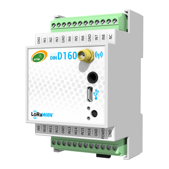
Set up a. Antenna positioning This version was designed for installation in a cabinet. If the latter is made of insulating materials (PVC, ABS, fiberglass), it is possible to simply use a small half wave whip antenna (Ref: ANT868-12FSC). This antenna must be correctly screwed on the SMA connector and positioned vertically, preferably upwards. - Page 14 c. Terminals’ description Below you will find a table describing the different connection pins: Name Designation Input / Output Ground (-) for IN1, IN2 and IN3 Ground Digital input ALERT 1 Input Digital input ALERT 2 Input Digital input ALERT 3 Input Ground (-) and IN4, IN5 and IN6 Ground...
-
Page 15: Pushbutton
The push button located on the front of the box makes it possible to send a test frame to validate the installation on site by checking the arrival of the message on the ATIM Cloud Wireless® platform. e. LEDs meaning The LEDs are used to characterize the proper operation or not of the ACW-DINDxxx. -
Page 16: Normal Behaviour At Startup
Normal behaviour at startup On power-up, after a moment, the GREEN LED flashes rapidly for about second, to attest to a good start. 1 minute after power up, 3 frames are sent: • 1 test frame • 1 keep alive frame •... -
Page 17: Setup And Configuration
Setup and configuration a. Setup Inputs setup All inputs are configurable and can be assigned to different operating modes. Each entry can be deactivated or assigned to one of 14 different events available. For each event, a trigger mode is associated among three different modes available, as well as the type of draw of entries. -
Page 18: Bounce Time Parameter
Bounce time parameter All inputs are affected by an anti-rebound time that can be adjusted between 1 and 250 ms depending on the type of dry contacts used. Periodic frame parameter The periodic frames make it possible to regularly go back up the state of the inputs / Meters. This frequency is set to 1 hour by default but can be set from 10 minutes to 45 days, 12 hours, and 15 minutes. -
Page 19: Pairing Method Setup
Pairing method setup In the LoRaWAN version it is possible to choose the method of pairing between OTAA (Over The Air Activation) and ABP (Activation By Personalization). NOTE The class of operation LoRaWAN is by default and not configurable, class C. This remains compatible with a network configured for class A. - Page 20 You can then see a window like the one below (eg for an ACW-DIND160, previously ACW-DINDIO16): In the upper left corner of the page is the product reference and a short description of its functionality. In the upper right corner, the type of radio embedded in the product is indicated (LoRa or Sigfox) In the "Input settings"...
- Page 21 The window below refers to a version with outputs, an ACW-DIND88: On this page there is an additional tab called "Test outputs" where you can test the outputs of the product by checking one or more boxes, which will activate the relevant output(s) of the product. It is also possible to activate or deactivate all outputs at once.
- Page 22 It is also possible to configure the output management programs by clicking on the give an access to the output calendar configuration tools: This window allows you to configure each program (the program number is indicated by "Program ID") by selecting the days on which the program will be activated, the start and end time of the program and the inputs to be activated or deactivated during the program.
-
Page 23: Uplinks On Iot Networks (Sigfox/Lorawan)
Uplinks on IoT networks (Sigfox/LoRaWAN) a. Test frame This frame is sent to the network every minute for five minutes when the product is started. It can also be triggered via the push button on the front of the ACW-DINDxxx. Each time this frame is sent, a Meter is incremented and inserted in the frame. -
Page 24: Digital Inputs Frame
Digital inputs frame In case the temperature sensor is disconnected and Meter 1 and Meter 2 are deactivated. Byte Data (for DIND160 or DIND80) 0x42 State of digital inputs Data (for DIND44 or DIND88) 0x62 State of digital inputs State of digital outputs Frame of digital IN/OUT and temperature In case the temperature sensor is connected, and all the Meters are deactivated. -
Page 25: Frame Of Digital In/Out And Meter 1
Frame of digital IN/OUT and Meter 1 In case only Meter 1 is activated and the temperature sensor is disconnected. Byte Data (for DIND160 or DIND80) 0x52 Digital inputs states Meter 1 Data (for DIND44 or DIND88) 0x72 State of digital inputs State of digital outputs Meter 1 Meters 1 &... -
Page 26: Frame Of Digital In/Out, Temperature And Meters 1 To N (Only Lorawan)
Frame of digital IN/OUT, temperature and Meters 1 to n (only LoRaWAN) In the case where Meters are activated, and the temperature sensor is connected. Byte … Temperature in Data (for DIND160 or DIND80) 0x5d Digital inputs states Meter 1 Meter 2 to n of °C State of... -
Page 27: Format/Decoding Of Data/Frames
e. Format/decoding of data/frames State of digital inputs (for DIND160 and DIND80) The layout of the digital inputs in bytes 2 and 3 for frames 0x41, 0x42, 0x4e, 0x4f, 0x5d, 0x5e and 0x52 are described in the table below. Byte 2 Input 1 Input 2 Input 3... -
Page 28: Examples Of Frames
Examples of frames For a digital input frame with temperature and Meter 1 of a DIND80 with the following values: • Digital inputs = 0xF5FF (Inputs 1 and 3 at 0; inputs 0,2,4,5,6,7 at 1; inputs 8 to 15 not used for this reference) •... -
Page 29: Frames Summary
f. Frames summary Frame format Type Description byte 0 byte 3 byte 4 byte 5 byte 6 byte 7 byte 8 byte 9 byte 10 byte 1 (hex) byte 2 (hex) (hex) (hex) (hex) (hex) (hex) (hex) (hex) (hex) (hex) Power supply Keep Alive Keep alive frame... -
Page 30: Downlinks From Iot Networks (Sigfox Ou Lorawan)
Downlinks from IoT networks (Sigfox ou LoRaWAN) If your product has a compatible radio version, you can benefit from this feature. • Sigfox radio firmware: Version 5931 or forward • LoRaWAN radio firmware: Version 2.3.3 or forward The operation of the exchange frames of this function is explained in the document "ATIM_ACW- DLConfig_UG_EN_Vx.x.pdf"... -
Page 31: Events - Bits 0 To 4
The value (0xYY) is composed of an event, a trigger mode and a draw type. The value (0xYY) is thus divided into three concatenated parts. NOTE The 8-input version (ACW-DINDIO8) does not have codes 18 to 25. NOTE The type of print and available only from version V1.2.0. Events - bits 0 to 4 The possible values in the byte for these bits are: •... -
Page 32: Rebound Time Parameter (Code 30)
EXAMPLE If you want to configure the input 10 (code 19) on the Meter 3 (0x05) on the rising edge only (0x40 and a pull up (0x00), the following parameterization must be generated: BSize and Code (Byte 0) Value (Byte 1) 0x00 | 19=0x13 0x05 | 0x40 | 0x00=0x45 The answer of the ACW will be:... -
Page 33: Output Calendar Configuration (Code 34 To 40)
Output calendar configuration (code 34 to 40) Frame size Start | Stop time Weekday Output to set Output to reset Size and Code (Byte 0) (Byte 1) (Byte 2 -4) (Byte 5) (Byte 6) (byte 7) Program 1: 0xc0|0x22 (34) = 0xE2 Program 2: 0xC0|0x23 (35) = 0xE3 Program 3: 0xC0|0x24 (36) = 0xE4 Program 4: 0xC0|0x25 (37) = 0xE5... -
Page 34: Shock Alarm Configuration (Code 41)
EXAMPLE If outputs 1,3,5,7 have to be set at “0” and outputs 2,4,6,8 to “1”, the value of byte 6 will be 0xAA (0b10101010) and byte 7 will be 0x55 (0b01010101). NOTE To let output undriven during a program, the corresponding bit in byte 6 and 7 should be set to “0”. Shock alarm configuration (code 41) Size and Code (Byte 0) Value (Byte 1) -
Page 35: Commands
b. Commands Frame format Command Byte 0 (hex) Byte 1 (hex) Byte 2 (hex) Byte 3 (hex) Byte 4 (hex) Byte 5 (hex) Byte 6 (hex) Byte 7 (hex) Restart 0x01 0x01 About 0x01 0x02 Reconfiguration with default settings 0x01 0x03 Get configuration 0x01... -
Page 36: Restart (Command 0X01)
Restart (Command 0x01) To restart the ACW-DIND80|160 remotely, you will need to send the following command: Byte 0 Byte 1 0x01 0x01 The ACW will restart and not send confirmation. About (Command 0x02) To obtain the information about the ACW-DIND80|160 it will be necessary to send him the following command: Byte 0 Byte 1 0x01... -
Page 37: Obtain The Complete Configuration (Command 0X04)
The ACW will return a confirmation in the following format: Description and Value Byte 0 Answer to command frames: 0x07 Byte 1 Configuration command by default: 0x03 Indicates whether the reconfiguration went well: − Byte 2 Returns 0x00 to indicate that the configuration went smoothly. −... -
Page 38: Apply A Value To The Meters (From Version V1.2.0) (Command 0X0A)
Apply a value to the Meters (from version V1.2.0) (Command 0x0A) To write the value of one or more Meters, it will be necessary to send him the following command: Byte 0 Byte 1 Byte 2 Byte 3 Byte 4 0xC1 Frame size - 0x06 0x0A... - Page 39 Each output is represented by a bit in byte 3. Byte 0 of byte 3 corresponds to output 1, bit 7 of byte 3 corresponds to output 8. In the version of the ACW with 4 outputs, the 4 most significant bits must be 0. Or, in other words, the outputs (which do not exist) 5, 6, 7 and 8 must be controlled at 0.
-
Page 40: Obtain The State Of Outputs (Command 0X20)
WARNING Byte 3 being different from 0, this indicates a pilot error and raises the bit of the invalid output (in this case the output 8). The command is ignored, and no output will be commanded! Obtain the state of outputs (Command 0x20) In the same way as to affect the state of the outputs it is possible to recover their current state. -
Page 41: Generate A Positive Pulse To An Outputs Group (Command 0X12)
The constituted frame has the same behavior as with the 0x10 command. The difference is that the errors are based on byte 4 of the (control) frame 0x11. On DIND44 outputs 5 to 8 can not be controlled, bits 4 to 7 of byte 4 of frame 0x11 must therefore be 0 to avoid errors. -
Page 42: Generate A Negative Pulse To An Outputs' Group (Command 0X13)
Generate a negative pulse to an outputs’ group (Command 0x13) It is possible to generate a negative impulse (1-> 0-> 1), for this it will be necessary to send him the following command: For Version < V1.5.0 Byte 0 Byte 1 Byte 2 Byte 3 Byte 4... -
Page 43: Enable/Disable Output Calendar (0X0B)
Enable/Disable Output calendar (0x0B) At any time, it is possible to turn one or more programs at once on/off with the following command: Byte 0 Byte 1 Byte 2 0x41 0x0B Output calendar state Each program is represented in byte 2 as follows: Byte 0 Byte 1 Byte 2... - Page 44 Technical support For any further information or technical question, you can open a ticket on our technical support dedicated webpage. ACW-DINDxxx_UG_EN_V1.10...
Need help?
Do you have a question about the ACW/LW8-DIND160 and is the answer not in the manual?
Questions and answers