Table of Contents
Advertisement
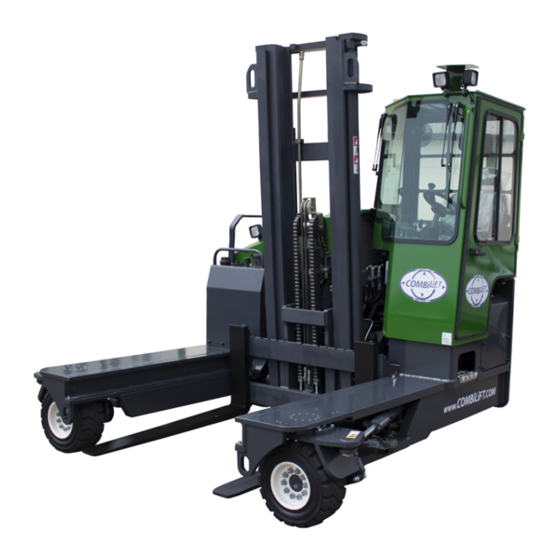
Combilift Ltd.
Operators & service
Manual
Models:
C3500kg / C4000kg / C4500kg / C4800kg / C5000kg / C5000XL
C6000lbs / C8000lbs / C9000lbs / C10,000lbs / C10,000XL
Serial Number: ___________
Combilift ltd.
Gallinagh
Co. Monaghan
Ireland
Tel: + 353 47 80500
Fax: + 353 47 80501
E-Mail: info@combilift.com
C4000-OM-EN-08 (c)
https://www.forkliftpdfmanuals.com/
Advertisement
Table of Contents


Need help?
Do you have a question about the C3500kg and is the answer not in the manual?
Questions and answers