Advertisement
Quick Links
ALESIS
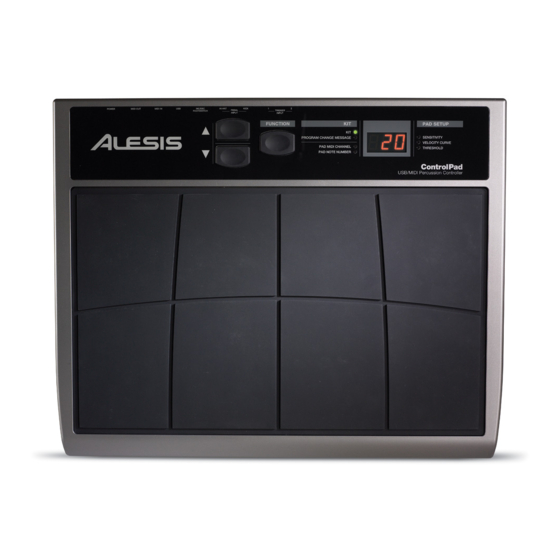
ControlPad (LDS1)
Service Manual
P/N: 8-31-0175-B
ATTENTION!
THIS DOCUMENT CONTAINS SENSITIVE
PROPRIETARY INFORMATION.
ALL RECIPIENTS MUST HAVE A CURRENT
NON-DISCLOSURE AGREEMENT ON FILE
WITH ALESIS, LLC.
DO NOT MAKE ILLEGAL
COPIES OF THIS DOCUMENT
The information in this document contains privileged and confidential information.
It is intended only for the use of those authorized by Alesis. If you are not the
authorized, intended recipient, you are hereby notified that any review,
dissemination, distribution or duplication of this document is strictly prohibited. If
you are not authorized, please contact Alesis and destroy all copies of this
document. You may contact Alesis at servicemanuals@alesis.com or at
support@alesis.com.
Copyright Alesis, LLC
Confidential
Alesis Service Manual
8-31-0175-B
Advertisement

Related Manuals for Alesis ControlPad


Summary of Contents for Alesis ControlPad
- Page 1 COPIES OF THIS DOCUMENT The information in this document contains privileged and confidential information. It is intended only for the use of those authorized by Alesis. If you are not the authorized, intended recipient, you are hereby notified that any review, dissemination, distribution or duplication of this document is strictly prohibited.
- Page 2 Your purchase of the Manual shall be for your own ultimate use and shall not be for purposes of resale or other transfer. As the owner of the copyright to the Manual, Alesis does not give you the right to copy the Manual, and you agree not to copy the Manual without the written authorization of Alesis. Alesis has no obligation to provide to you any correction of, or supplement to, the Manual, or any new or superseding version thereof.
- Page 3 ALL REPAIRS DONE BY ANY ENTITY OTHER THAN AN AUTHORIZED ALESIS SERVICE CENTER SHALL BE SOLELY THE RESPONSIBILITY OF THAT ENTITY, AND ALESIS SHALL HAVE NO LIABILITY TO THAT ENTITY OR TO ANY OTHER PARTY FOR ANY REPAIRS BY THAT ENTITY.
-
Page 4: Safety Instructions
The product is exposed to water or excessive moisture, c. The AC power supply plug or cord is damaged, d. The product shows an inappropriate change in performance or does not operate normally, or e. The enclosure of the product has been damaged. Confidential Alesis Service Manual 8-31-0175-B... -
Page 5: Specifications
2 EXTERNAL TRIGGER INPUTS These two ¼” inputs can be used for connecting external triggers, pads, and pedals. Alesis offers a pad expansion kit, as well as a cymbal expansion kit sold separately. 2 SINGLE FOOTSWITCH INPUTS These two ¼” inputs are used for connecting external footswitches to function as a high hat pedal or bass drum pedal. -
Page 6: Power Adapter Input
The USB port is used to transmit MIDI data between the ControlPad and a computer. If you are using the USB port, there will be no need for the power adapter to be plugged in – the ControlPad will be powered through the USB bus. MIDI IN PORT Use a five-pin MIDI cable to connect the OUTPUT of another ControlPad to this MIDI IN port. -
Page 7: Disassembly Procedures
DISASSEMBLY PROCEDURES 1. DISASSEMBLE THE CABINET (Fig1) (A) REMOVE 15 SCREWS FROM TOP CABINET. (B)(C) REMOVE 2 CABLES. (Fig1) 2. DISASSEMBLE THE FRONT PANEL PCB ASS’Y. (Fig2) (A)REMOVE 6 SCREWS FROM THE CABINET. (Fig.2) - Page 8 3.DISASSEMBLE THE MAIN PCB ASS’Y. (Fig3) (A) REMOVE 5 1/4” JACK NUTS. (B) REMOVE 3 SCREWS. (Fig.3)
- Page 12 ALESIS ControlPad (LDS1) SCHEMATIC FILES Confidential Alesis Service Manual 8-31-0175-B...
- Page 29 ALESIS ControlPad (LDS1) Confidential Alesis Service Manual 8-31-0175-B...
- Page 30 CONTROL PAD BOM DESCRIPTION LEVEL AL4-71-0016 CABLE USB RF CHOKE AL7-51-0154-F OPERATION MANUAL AL7-91-1002 GEL SILICA AL9-11-1011 ALPHA KNOB AL9-63-0005-C CGLDS1513ALE01 INNER CARTON CN1220006201 CONNECTOR(5P) CTLDS1513ALE01 CARTON EVA1304433 DOUBLE ADHESIVE TAPE GEALE03 SOFTWARE INSTALLATION PROCEDUL GEALE04 BFD DEMO POSTCARD LAC22ALE47 BAR CODE LABEL LAC52ALE01 LABEL...
- Page 31 WR003212010B 5P WIRE 150MM AL9-79-0410 MAIN PCB ASS'Y AL0-17-0272 RESISTOR R40,51 AL0-17-0273 RESISTOR R3~6,39,50 AL0-17-0274 RESISTOR R41,42 AL0-17-0332 RES ARRAY 4X330 R25,34 AL0-17-0470 RES 4X47 1/16W 0603 R26,35 AL1-51-0475 C.CAP 150P/50V C13,21,22,27 AL1-55-0189 CAP 18PF NPO 0805 C32,43 AL1-56-0102 CAP 1000PF NPO 100V 0805(SMD) C2,8~11 AL1-56-0104 CERAMIC...
- Page 32 TE952542001 TERMINAL 20P 2.54MM AL9-79-0413 FRONT PANEL PCB ASS'Y AL3-02-0054 AL3-04-0017 AL6-02-0033 SWITCH S1~3 AL9-40-0413 FRONT PANEL PCB BALE48201-5A LED FIXED (D1~6,8) CN2025402301 20P CONNCTOR JW5206T JUMPING WIRE LDIFR324HD LED RED 3M/M D1~6,8...
Need help?
Do you have a question about the ControlPad and is the answer not in the manual?
Questions and answers