Table of Contents
Advertisement
Quick Links
Advertisement
Table of Contents

Related Manuals for Diamond GTP-5P

Summary of Contents for Diamond GTP-5P
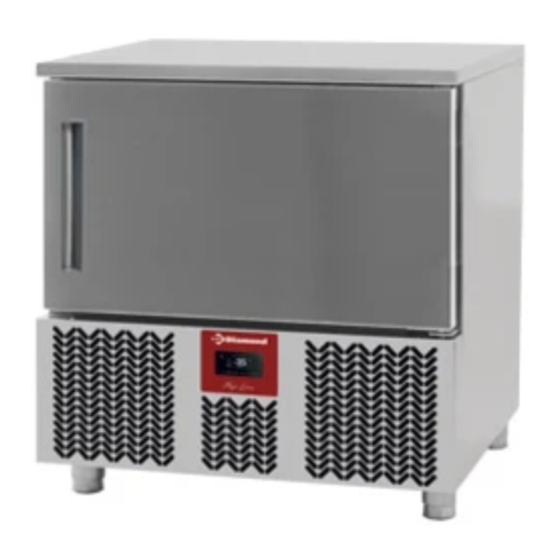
- Page 1 06/2012 Mod: GTP-5P Production code: 18G314000000...
- Page 2 INSTALLATION, USAGE AND MAINTENANCE MANUAL:...
-
Page 3: Table Of Contents
INSTALLATION, USAGE AND MAINTENANCE MANUAL: COOLERS CONTENTS INSTALLATION............................17 SITING ..............................17 CLEANING............................17 GENERAL............................. 17 GENERAL MEASUREMENTS......................18 USE................................19 – ENVIRONMENTAL DATA ....................... 19 – CONSTRUCTION DATA ......................... 19 – USAGE ............................. 20 – PRODUCTION ..........................20 – CONTROL PANEL INSTRUCTIONS....................21 OPERATIONAL CYCLES ........................ -
Page 4: Installation
INSTALLATION, USAGE AND MAINTENANCE MANUAL Before starting the cooler up, we would like to thank you for the confidence you have placed in us on purchasing this machine, and recommend you read and follow the steps detailed in the instructions. This manual is designed to offer the information necessary for the installation, start-up, and maintenance of the Temperature Coolers. -
Page 5: General Measurements
It is essential that the electrical installation where it is going to be connected has an EARTHING SOCKET, in addition to the appropriate protection of the magneto-thermal switch and differential (we recommend 30 mA.) For your safety, it is prohibited to lengthen this power cable. Do not insert any elements through the fan guard or refrigerator equipment area grilles. -
Page 6: Use
5GN 1/1 2.0 – ENVIRONMENTAL DATA Room temperature. The production data have been carried out in a technical laboratory with the following environmental conditions: 38 ºC in the premises. Noise level Leq in the point with noise level at 1 metre and in operating conditions <70 dB(A) Lpc at 1 metre in operating conditions <130 dB(C) The measurements of the acoustic tests have been carried out according to ISO 230-5, in a rectangular shaped exposure room without sound-absorbent treatments. -
Page 7: Usage
Injected polyurethane insulation. Density of 40 kg. Without CFC. Copper tube evaporator and aluminium flanges with anticorrosive paint. Refrigeration by forced draught. 2.2 – USAGE These machines have been built according to the EC directives regarding food treatment and preservation. The use of the cooler consists of lowering the temperature suddenly from a level (cooked or fresh products) to another level that guarantees the maintenance of the ideal nutritional, physical and chemical properties of the food. -
Page 8: Control Panel Instructions
2.4 – CONTROL PANEL INSTRUCTIONS Key Description Button Up Timed Chilling Button Set Set-temperature Chilling Button Down Storage ºC ºF Degree Celsius Degree Fahrenheit Alarm TIMED CHILLING IF ON and the LED is off, a timed chilling operation is ongoing. If ON and the LED is also post timed-chilling storage operation is ongoing. -
Page 9: Operational Cycles
In “STAND-BY” mode, during normal operation, the display shows the temperature of the cabinet for ½ s every 3 s. 2.5 OPERATIONAL CYCLES The device has the following operational cycles: • timed positive chilling and storage • timed positive chilling and storage •... -
Page 10: Set-Temperature Soft Positive Blast Chilling And Storage Cycle
- Press within 15 s: the display will show the duration of the blast chilling step (in minutes) - Press within 15 s to change the value (the setting remains active until another cycle is selected, when the value assigned by parameter r2 is restored) - Press within 15 s: the cycle will be activated. -
Page 11: Set-Temperature Hard Positive Chilling And Storage Cycle
- The parameter r5 sets the maximum chilling time duration - The parameter r7 sets the operational set-point - Press several times to: Display the message “PoS”; Display the flashing cabinet temperature; Exit the procedure, or leave for 15 s. If the temperature measured by the pin probe reaches the chilling endpoint temperature prior to expiry of the maximum chilling time duration, the device will switch to storage mode and the display will show the message “End”. -
Page 12: Temporary Setting Of Operational Setpoint During Storage
- Press several times to: Display the maximum residual chilling time remaining Display the message “nEg”; Display the flashing cabinet temperature; Exit the procedure, or leave for 15 s. If the temperature measured by the pin probe reaches the chilling endpoint temperature prior to expiry of the maximum chilling time duration, the device will switch to storage mode and the display will show the message “End”. -
Page 13: Test To Check Correct Pin Probe Insertion
TEST TO CHECK CORRECT PIN PROBE INSERTION 2.12 Set-temperature cycles are preceded by a test step in order to check correct pin probe insertion. The test has two stages: • The outcome of the first stage is positive if “the temperature measured by the pin probe - the temperature of the cabinet”... -
Page 14: Alarms And Errors
If the display shows “F-0”, the evaporator fan will be switched off If the display shows “F-P”, then evaporator fan deferred activation will be ongoing (parameter F8). To exit the procedure: - Press until the display shows the ongoing status value, or leave for 15 s. If the service controlled by relay K2 is defrosting (parameter u0 = 0), labels “F-1”, “F-0”... -
Page 15: Usage Precautions
To modify a parameter: - Press - Press within 15 s - Press or leave for 15 s. To exit the procedure: - Press for 4 s, or leave for 60 s. Interrupt the device power supply after modify the parameters. RESETTING CONFIGURATION PARAMETER DEFAULT VALUES - Ensure the device is in “stand-by”... -
Page 16: Regular Checks
The inside of the cooler should be cleaned with great care. 3.1 REGULAR CHECKS To be carried out by the User - It is recommended that there are no heat sources near to the cooler. - The appliance should be well levelled to prevent excessive vibrations. - The door Joint is in good working conditions and closes hermetically with the body. -
Page 17: Testing And Guarantee
3.5 TESTING AND GUARANTEE The cooler has been tested the outcome of which has been satisfactory after the tests established for its production. The supplier may ask for the faulty part to be returned for analysis and statistics. The company will correct any possible errors or faults as long as the machine has been used according to the manual's indications.
Need help?
Do you have a question about the GTP-5P and is the answer not in the manual?
Questions and answers