Table of Contents
Advertisement
Quick Links
© 2018 TE Connectivity family of companies
All Rights Reserved
| Indicates Change
*Trademark. TE Connectivity, TE connectivity (logo), and TE (logo) are trademarks. Other logos, product, and/or company names may be trademarks of their respective owners.
Application
Specification
Class 1
EV Charge Inlet Combo 2
114-94467 Rev. C
10 OCTOBER 2018
1 of 31
Advertisement
Table of Contents

Related Manuals for TE Connectivity EV Charge Inlet Combo 2


Summary of Contents for TE Connectivity EV Charge Inlet Combo 2
- Page 1 © 2018 TE Connectivity family of companies 1 of 31 All Rights Reserved | Indicates Change *Trademark. TE Connectivity, TE connectivity (logo), and TE (logo) are trademarks. Other logos, product, and/or company names may be trademarks of their respective owners.
-
Page 2: Table Of Contents
114-94467 Rev. C Content SCOPE ............................3 Content ................................. 3 Processing Note ............................3 APPLICABLE DOCUMENTS ......................4 Customer drawings for COMBO 2 INLET ....................4 Specifications .............................. 4 WIRES............................5 Assessment of the wires ..........................5 Wire selection .............................. 5 Wire preparation ............................ -
Page 3: Scope
114-94467 Rev. C SCOPE Content This specification describes the handling and assembly of the vehicle charge inlets CCS 2 acc. IEC 62196-3 for conductive charging of electric vehicles. This specification applies to manual assembly of the components from series production tooling, for the standard version. The usage of single wire sealing in the charge inlet is described. -
Page 4: Applicable Documents
114-94467 Rev. C APPLICABLE DOCUMENTS The following technical documents, if referred to, are part of this specification. In case of a contradiction between this specification and the product drawing or this specification and the specified documentation, the product specification has priority. Customer drawings for COMBO 2 INLET INLET HSG, COMBO 2, ASSY 2306836... -
Page 5: Wires
114-94467 Rev. C WIRES The following designations are used in this specification. The illustrations are exemplary and schematically. Assessment of the wires To ensure the required electrical crimp contactability with stable crimp resistance a permissible maximum storage period of 8 months for unprocessed cable (referring to cable manufacturer production date) must be respected. Wire selection The contact system is released for the application with wires specified in Chapter 3.4. -
Page 6: Application Tools & Crimp
114-94467 Rev. C DC-HV-cable: Cross-section 35,0mm² Supplier: Coroplast Outer Diameter 14,4 -0,6 Cable description: FHLR2GCB2G 35mm² acc. LV216-2 table A.2 Supplier Part No.: 9-2611 / 35mm² APPLICATION TOOLS & CRIMP To produce a correct wire crimp, as validated by TE with the wires listed in this specification, following application tools are required. -
Page 7: Requirements On The Crimped Contacts
114-94467 Rev. C REQUIREMENTS ON THE CRIMPED CONTACTS The following terms shown below are used in this Specification, see Figure 1 and Figure 2. Figure 1 Figure 2 Conductor position The single strands of the conductor are clamped inside the crimp area. All single strands need to be caught in the crimp and not a single strand must remain outside the crimp. -
Page 8: Crimp Geometry
114-94467 Rev. C Crimp Geometry The crimp geometry, crimp heights including their corresponding tolerances as well as wire sizes are given in Table 1. The crimp height is the key quality feature of a crimp connection. The measurement allows a non-destroying examination and a continuous process inspection. -
Page 9: Crimp Position
114-94467 Rev. C Crimp Position Contacts of wire cross-section 6mm² must be crimped with crimping tool position at middle of crimp area as shown in Figure 6 and Figure 7. Figure 6 (picture exemplarily) Figure 7 (picture exemplarily) 9 of 31... - Page 10 114-94467 Rev. C Contacts of cross-section 16 mm² and 35 mm² must be crimped with crimping tool position at end of crimp area as shown in Figure 8 and Figure 9. Figure 8 (picture exemplarily) Figure 9 (picture exemplarily) 10 of 31...
-
Page 11: Contact Area
114-94467 Rev. C Contact area During processing and following processing the contact area may not be damaged or bended. Sealing Area During processing and following processing the sealing area may not be damaged or bended. Shape and position tolerances Measuring the shape and position deviation is not always necessary, if the contact is obviously straight by eye. In case a measurement is required, the measurement equipment requires at least a 10-time better measuring precision compared with the requirement tolerances, see Figure 10 and Figure 11. -
Page 12: Measuring Equipment And Measuring Position
114-94467 Rev. C Measuring equipment and measuring position As measuring equipment for measuring crimp height, a digital caliper with an accuracy of measuring 0,01 mm is the minimum requirement. Measuring of crimp height must be done according as following always in middle of crimp area across whole crimp, see Figure 12. -
Page 13: Assembly Instructions
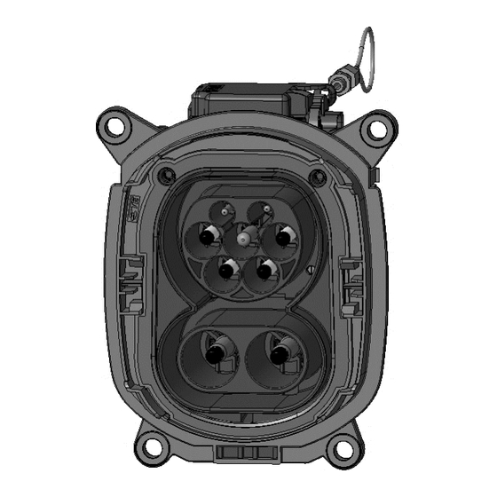
114-94467 Rev. C ASSEMBLY INSTRUCTIONS Assembly overview Charge Inlet COMBO 2 Figure 13 13 of 31... -
Page 14: Parts To Order
114-94467 Rev. C Parts to order Charge Inlet COMBO 2 3-phase AC 6mm² Variant PE 16 mm² DC 35 mm² Part Pos. Qty. Description INLET HSG, COMBO2, ASSY 2306836-2 Additional part for charge inlet cabling: 12POS MICRO MNL HSG 1-794617-2 Additional part for charge inlet cabling: CONTACT MICRO MNL 794606-1... -
Page 15: Security Advice
114-94467 Rev. C Security Advice Figure 14 Figure 15 The assembly should only be performed by trained personnel! Avoid prolonged or repeated skin contact with silver plated contacts (wear protective gloves)! 15 of 31... -
Page 16: Assembly Steps
114-94467 Rev. C Assembly Steps Step 1 The COVER CAP AC 2296057-1, STRAIN RELIEF AC 2296056-7 and FAMILY SEAL AC 2296040-7 must be pushed over the signal wire, the PE cable and the AC-Multicore cable. Pay attention to place all wires at correct positions, per Figure 16. - Page 17 114-94467 Rev. C Figure 18 Removal of insulation Length of single Removal of insulation Length of single wire wires dim. “B” dim. "C” dim. “D” Wire dim. "A" Size (valid for 4 single (valid for 4 single (valid for 1 single (valid for 1 single wires) wires)
- Page 18 114-94467 Rev. C Step 4 Dismantle the wires and crimp the contacts: 0.35 mm² Signal Wires Remove outer cable sheath, cut one of the 12 single wires right after the cable sheath and remove the single wire insulation from the remaining 11 single wires acc. Figure 20 and Table 5. Figure 20 Length of single wires dim.
- Page 19 114-94467 Rev. C Step 6 Insert the uncrimped single wire from the 5 x 6 mm² AC-Multicore cable into the empty aperture of the FAMILY SEAL AC 2296040-7, STRAIN RELIEF AC 2296056-7 and COVER CAP AC 2296057-1 like shown in Figure 22. Figure 22 After completing the last step, the AC cable sub-assembly is finished.
- Page 20 114-94467 Rev. C Figure 24 Step 8 Dismantle the wires and crimp the contacts: 35 mm² DC-HV cable Remove outer insulation, shielding braid and inner insulation acc. Figure 25 and Table 6. Figure 25 Removal of shielding dim “B” Wire Size Removal of insulation dim.
- Page 21 114-94467 Rev. C Step 9 The two SEALS 2120571-1 must be placed on the crimped PIN DIA8.0 POWER DC 2292542-2 as shown in Figure 26. Ensure correct orientation of seal acc. Figure 27 (sealing lips on outside). Figure 26 Figure 27 After completing the last step, the DC cable sub-assembly is finished.
- Page 22 114-94467 Rev. C Step 10 Assemble the RADIAL SEAL 2320511-1 to the CABLE EXIT COVER 2307523-1 like shown in Figure 28. The seal should be properly seated onto the collar of the cable exit. Ensure also correct orientation of seal acc. Figure Figure 28 Figure 29 22 of 31...
- Page 23 114-94467 Rev. C Step 11 Pass the AC cable sub-assembly (Figure 22) through the AC slot and the DC cable sub-assembly (Figure 27) through the DC slot in CABLE EXIT COVER 2307523-1 like shown in Figure 30. Figure 30 Step 12 Insert the contacts from the backside into the INLET HOUSING 2306836-2 according the cavity description (shown in Figure 31) into their locking position, see Figure 32.
- Page 24 114-94467 Rev. C ATTENTION: The correct contact positions have to be ensured BEFORE pushing the contacts into their cavities in locking position. In case of wrong positioning of the contacts the complete assembly has to be scrapped. There is no rework allowed (risk of damaging contacts and/or locking geometry in housing)! ESD safety required –...
- Page 25 114-94467 Rev. C Step 13 After the contacts have been controlled for correct positioning and locking, the SECONDARY LOCKS must be pushed upwards (see Figure 34). Ensure that all hooks are properly engaged with the inlet housing, which should be controlled by the double audible click and by visible inspection. Secondary locks in correct end position are shown in Figure 35.
- Page 26 114-94467 Rev. C Step 14 Connect Micro Mate-N-Lok Connector to PCB-Header. Ensure that the locking latch is properly engaged with the PCBA header, see Figure 36. ESD safety required – The printed circuit boards are static sensitive devices, which can be damaged if touched without the necessary electrostatic discharge (ESD) precautions.
- Page 27 114-94467 Rev. C Step 15 Assemble the CABLE EXIT COVER 2307523-1 to the INLET HOUSING 2306836-2, see Figure 37. The press force should be applied on the marked locations close to the latches, as shown in Figure 38. Ensure that all 5 hooks are properly engaged.
- Page 28 114-94467 Rev. C Step 16 Move the STRAIN RELIEF AC 2296056-7 together with FAMILY SEAL AC 2296040-7 into their position in the CABLE EXIT COVER 2307523-1, as shown in Figure 39. ATTENTION: Ensure that the AC-Multicore cable and the Signal Wire are well positioned in the FAMILY SEAL 2296040-7, so that all seal lips are safely placed on the outer insulation of the cables.
- Page 29 114-94467 Rev. C Step 17 Assemble PROTECTION CAP 2292534-1 to INLET HOUSING 2306836-2, as shown in Figure 40. Figure 40 Step 18 For identification apply a label on this specified polished face on the CABLE EXIT 2307523-1, see Figure 41. The label needs to include information acc.
-
Page 30: End Of Line Test
114-94467 Rev. C END OF LINE TEST ATTENTION: The assembled Charge Inlet must be tested electrically and mechanically to applicable requirements, including High Voltage test. As a minimum, the following tests should be performed: • Isolation Resistance: Test Voltage: 500 V DC Inspection Duration: 1 s min. - Page 31 CHANGED FROM 65 MM TO 60 MM, PERIPHERAL C. RINGLSTETTER F. WITTROCK 10OCT2018 SEAL 8-2320511-1 CHANGED TO 2320511-1 (POS. 5 IN TABLE 2) C. RINGLSTETTER TE CONNECTIVITY GERMANY GMBH 17OCT2017 AMPÈRESTRASSE 12-14 D-64625 BENSHEIM GERMANY F. WITTROCK 17OCT2017 F. WITTROCK...
Need help?
Do you have a question about the EV Charge Inlet Combo 2 and is the answer not in the manual?
Questions and answers