
Summary of Contents for GHS Corporation Rocktron Patchmate Loop & Floor
- Page 1 MANUAL May be covered by one or more of the following: U.S. Patents #4538297, 4647876, 4696044, 4745309, 4881047, 4893099, 5124657, 5263091, 5268527, 5319713, 5333201, 5402498 and 5493617. Other patents pending. Foreign patents pending.
-
Page 2: Specifications
Provided on MIDI IN jack pins 6 and 7 - 9VAC 2 amps Presets MIDI program change 0-127 Midi control Change commands in groups of 8 with 16 banks 0-7, 8-15, 16- 23....120-127 Relays Gas filled, contacts gold plated Copyright © 2009 GHS Corporation. All rights reserved. -
Page 3: Operating Temperature
PRECAUTIONS NOTE: IT IS VERY IMPORTANT THAT YOU READ THIS SECTION TO PRO- VIDE YEARS OF TROUBLE FREE USE. THIS UNIT REQUIRES CAREFUL HAN- DLING. • All warnings on this equipment and in the operating instructions should be adhered to and all operating instructions should be followed. •... - Page 4 Introduction The PatchMate LOOP 8 Floor provides 8 discrete Loops all with True Bypass, Buffered and non buff- ered signal paths, 128 programmable presets with Real time control using the 9 high quality metal foot switches. The eight LOOPs may be configured for multiple purposes including Channel switching, effects loops, guitar routing and more.
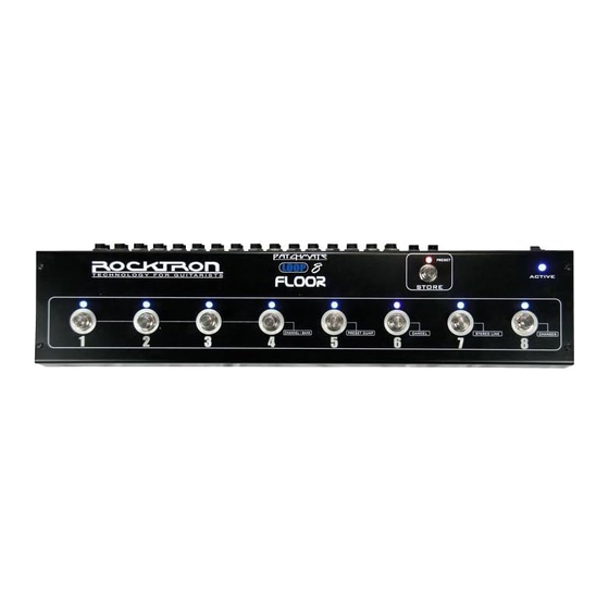
- Page 5 PatchMate LOOP 8 Floor Top Panel 1 LOOP Switches These switches are used to turn "on/off" each individual loop. The LED above each switch will display the "current" status of the PatchMate. If an LED above a switch is lit, that LOOP is ac- tive.
- Page 6 PatchMate LOOP 8 Floor Top Panel Continued..6 CHANGES Function In this function switch 8 is used to select if you would like the PatchMate LOOP 8 Floor to respond to MIDI Program changes and MIDI Controller changes or not. See the section in this manual called "CHANGES Function"...
- Page 7 PatchMate LOOP 8 Floor Top Panel Side Panel 1 ACTIVE Input Jack Plug your guitar into this jack to use the buffered input. This ACTIVE Input Jack is connected to an active buffer that helps maintain signal strength when driving multiple devices in paral- lel.
- Page 8 PatchMate LOOP 8 Floor Back Panel NOTE: The following example is to illustrate a serial chain of effects and how the Patchmate Loop 8 Floor may be applied. It is not necessary to daisy chain each LOOP in the order listed below. You may use any LOOP you desire and in any order you choose.
- Page 9 PatchMate LOOP 8 Floor Back Panel...continued..9 PASSIVE/ACTIVE OUTPUT Jack Use this jack to plug into the next unit in your signal chain or the desired LOOP. This jack can also be used as an output for the guitar signal when splitting the signal. This jack is the output for the PASSIVE/ACTIVE input jack located on the side panel of the PatchMate LOOP 8 Floor.
- Page 10 Individual LOOP Jacks Descriptions 1 IN Jack This is the first jack in the signal chain. The audio signal will enter the "LOOP" through this jack. 2 SEND - N.C. Jack This jack is used to send the signal to the desired audio device. 3 RETURN Jack This jack is used to receive the returned signal from the desired audio device..
- Page 11 Connections Note: to simplify the connection diagrams, all of the jacks may not be shown in similar locations as on unit, but the jack descriptions will show the correct connections This connection diagram shows one way to use the LOOPs in the PatchMate LOOP 8 Floor to connect stompboxes (pedals).
- Page 12 Connections..continued..This connection diagram shows one way to use the LOOPs in the PatchMate LOOP 8 Floor Although only two connections are shown here, you can follow a similar progression of connects using LOOPs 3-8.
- Page 13 Connections..continued..This connection diagram shows one way to use the LOOPs in the PatchMate to connect to multiple ef- fects processors.
- Page 14 Connections..continued..This connection diagram shows one way to use the LOOPs in the PatchMate to connect to two different preamp. OUT - N.O. RETURN SEND - N.C. �� �� ���� � ��� �� �� �� ��� �� ���� ���� ������ � ������...
- Page 15 Connections..continued..This connection diagram shows one way to use the LOOPs in the PatchMate to connect two amplifiers and select between the two.
- Page 16 Connections..continued..This connection diagram shows one way to use the PatchMate LOOP 8 Floor's SENDS to change change channels on an amplifier.
- Page 17 Connections..continued..This connection diagram shows one way to use the PatchMate's buffered connection.
- Page 18 Connections..continued..This connection diagram shows one way to use the PatchMates buffered connection to connect to two different preamps.
- Page 19 Connections..continued..This connection diagram shows one way to connect the PatchMate to "MUTE" an effects processor where parallel effect routings are being implemented.
- Page 20 Connections..continued..This connection diagram shows how to connect the PatchMate to a MIDI Controller such as the Rocktron MIDI Mate (use similar connections for the Rocktron All Access, All Access LTD and MIDI Xchange. Note: Internal PHANTOM POWER is provided by the PatchMate LOOP 8 Floor via the MIDI IN con- nector pins 6 &...
-
Page 21: Loop Mode
LOOPS and PRESETS Descriptions- Creating & Storing: The PatchMate LOOP 8 Floor has two basic MODES of operation, LOOP MODE (Default) and PRE- SET MODE. LOOP MODE LOOP Mode is when the PatchMate is in a state where you can access (turn on/off) the individual "loops"... - Page 22 PRESETS - Selecting, Creating & Storing: To create and store a preset follow these instructions To select a preset Press and Release the "STORE" Switch. The LED next to the word "PRESET" will light. Press the desired PRESET number using the switches on the top panel. Switch Number 1 is preset number 1 and so on.
- Page 23 Setup your PatchMate LOOP 8 Floor: SETUP MODE: To enter setup mode once you turn the power on you have 3 seconds to press the Store button once. After the 3 second time out it will enter the SETUP MODE..and the STORE LED will blink. You are now in the MIDI CONFIGURATION PROGRAMMING MODE.
-
Page 24: Midi Channel Select
MIDI Channel Select... - Page 25 MIDI Controller Bank Setup 3. Once you have pressed the Store switch from step 2, the TOP PANEL SWITCH LEDs [ 1 thru 8 ] will blink twice and the STORE BUTTON will continue to blink signifying that the MIDI CONTROLLER BANK information is now being displayed.
- Page 26 MIDI Controller Bank Setup *CANCEL: PRESS SWITCH 6 then PRESS and RELEASE the STORE BUTTON to CANCEL the PROGRAM- MING MODE. Note: If CANCEL is executed any modified information will not be retained.
-
Page 27: Preset Dump
Preset Dump MIDI PRESET DUMP PROCEDURE: To DUMP or copy presets from your PatchMate LOOP 8 Floor to another PatchMate LOOP 8 Floor, first connect the two via MIDI OUT of the sending PatchMate LOOP 8 Floor to the MIDI IN of the receiving PatchMate LOOP 8 Floor. -
Page 28: Stereo Link
Stereo Link To link loops in Stereo, follow these instructions 1. Turn the PatchMate LOOP 8 Floor "ON", then press and hold the STORE button down until the STORE LED starts "flashing". Note that this procedure must be done within 3 seconds of the PatchMate LOOP 8 Floor being turned "ON"... - Page 29 How to use an external MIDI Controller with the PatchMate LOOP 8 Floor SETTING PatchMate USING MIDI PROGRAM CHANGES Now that you have configured your PatchMate LOOP 8 Floor MIDI CHANNEL to the same channel as your midi controller along with enabling PROGRAM CHANGES ON, you are now ready to program your presets.
- Page 30 How to use an external MIDI Controller with the PatchMate LOOP 8 Floor..continued..On the initial reception of this ON state value the target relay will be activated followed by the execu- tion of the delay release timer. Note: When this feature is being used any transmitted value of 0 will be ignored as the delay will handle the off state execution.
- Page 32 Rocktron -A Division of GHS Corporation 2813 Wilber Avenue Battle Creek MI 49037 Rocktron Phone: 1-(269)-968-3351 Email: info@rocktron.com Check us out on the web at: www.rocktron.com 2009-0001 Rev. 5/19/09...
Need help?
Do you have a question about the Rocktron Patchmate Loop & Floor and is the answer not in the manual?
Questions and answers