Table of Contents
Advertisement
Quick Links
Advertisement
Table of Contents

Subscribe to Our Youtube Channel
Related Manuals for Coastal WEATHERPAK EOC

Summary of Contents for Coastal WEATHERPAK EOC
- Page 1 WEATHERPAK ® Operations & Maintenance Manual November 26, 2012 ©2012 Coastal Environmental Systems, Inc. P/N: 0302-117-004 Rev. 0 820 First Avenue South Seattle, WA 98134 www.CoastalEnvironmental.com ( 206 ) 682-6048 ( 800 ) 488-8291 Fax: ( 206 ) 682-5658 ISO 9001:2008 Certified...
-
Page 2: Table Of Contents
® WEATHERPAK Operations & Maintenance Manual Table of Contents Table of Contents ......................ii List of Figures ........................ iii List of Tables ........................iv IMPORTANT NOTES ......................v 1. SYSTEM OVERVIEW....................1 Introduction ............................1 Siting Considerations ........................2 1.2.1 Compass Accuracy ............................. -
Page 3: List Of Figures
® WEATHERPAK Operations & Maintenance Manual List of Figures Figure 2.1 – Power Over Ethernet Injector ..................... 4 Figure 2.2 – Power Over Ethernet Splitter in J Box ..................5 Figure 2.3 – System Data and Power Flow Diagram ..................5 P/N: 0302-117-004 Rev. - Page 4 ® WEATHERPAK Operations & Maintenance Manual List of Tables Table 2-1 – Wind Sensor Specification Data ....................6 Table 2-2 – AT/RH Sensor Specification Data ....................7 Table 2-3 – Barometer Specification Data ...................... 7 Table 3-1 – Scheduled Maintenance Intervals Summary (Days) ..............9 Table 3-2 –...
-
Page 5: Important Notes
® WEATHERPAK Operations & Maintenance Manual IMPORTANT NOTES Please call Coastal Environmental Systems if any issues arise or if you have questions regarding ® the WEATHERPAK EOC. Coastal Environmental Systems, Inc. 820 First Avenue South Seattle, WA 98134 Main: 800-488-8291 • Fax: 206-682-5658 Parts &... -
Page 6: System Overview
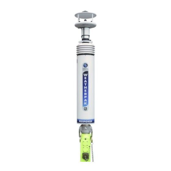
® WEATHERPAK Operations & Maintenance Manual SYSTEM OVERVIEW Introduction ® The WEATHERPAK EOC measures wind speed, wind direction, air temperature and GPS. ® Options for the WEATHERPAK EOC include relative humidity, barometric pressure, gamma ® radiation sensor, radio transmitter, base station, and 3 types of software; INTERCEPT (single ®... -
Page 7: Siting Considerations
® WEATHERPAK Operations & Maintenance Manual This manual will familiarize you with the installation, operation, and maintenance of the ® WEATHERPAK EOC. Please read all of the instructions before attempting to operate or troubleshoot the system. Siting Considerations 1.2.1 Compass Accuracy ®... - Page 8 ® WEATHERPAK Operations & Maintenance Manual BP – Barometric pressure in millibars RH – Relative humidity in percent (if available) CKSUM2 – Second checksum SAT – Number of satellites acquired GMT – Greenwich Mean Time LAT – GPS Latitude LON – GPS Longitude CKSUM3 –...
-
Page 9: Method Of Operation
® WEATHERPAK Operations & Maintenance Manual METHOD OF OPERATION Introduction This section provides detailed information about the system components and their interactions. System Power 2.2.1 Power Over Ethernet (POE) ® Power is supplied to the WEATHERPAK EOC via a Power Over Ethernet (POE) Injector. The POE Injector is an indoor piece of equipment requiring an AC outlet providing 100-240V AC 50/60 Hz (see Figure 2.1). -
Page 10: System Signal And Data Flow
® WEATHERPAK Operations & Maintenance Manual Figure 2.2 – Power Over Ethernet Splitter in J Box System Signal and Data Flow ® Data flow from the WEATHERPAK EOC is via the same Ethernet cable that provides power to ® the WEATHERPAK EOC. -
Page 11: Sensors
® WEATHERPAK Operations & Maintenance Manual Sensors The system uses COTS (commercial off the shelf) sensors. A brief description of each sensor, including sensor specifications, is provided in the following sections. 2.4.1 Wind Sensor The wind sensor measures both horizontal wind speed and wind direction. The wind sensor is ®... -
Page 12: Barometer (Optional)
® WEATHERPAK Operations & Maintenance Manual Table 2-2 – AT/RH Sensor Specification Data Operating Temperature Range -30 °C to +60 °C Measuring Range 0 to 100 %RH Output Scale 0 ... 100 %RH equals 0 ... 1 VDC RH Accuracy + 3% Temp Accuracy + 0.6°C... -
Page 13: Software
® WEATHERPAK Operations & Maintenance Manual fast and powerful computing of multiple routines and uses advanced power management for very low power consumption. A true real-time executive is used to achieve multi-tasking which ® samples and communicates simultaneously. The ZENO Datalogger operates using embedded firmware. -
Page 14: Maintenance
® WEATHERPAK Operations & Maintenance Manual MAINTENANCE Recommended Preventive Maintenance Schedule NOTE In certain locations, local conditions may warrant more frequent cleaning and corrosion control. Table 3-1 – Scheduled Maintenance Intervals Summary (Days) Equipment General Corrosion Cleaning Control ® WEATHERPAK Wind Sensor Consumable Items Needed for Maintenance Table 3-2 –... -
Page 15: Scheduled Maintenance
® WEATHERPAK Operations & Maintenance Manual Scheduled Maintenance 3.3.1 Wind Sensor Material Required Cloth, Cotton, Lint-free Mild detergent w/ water a. Inspect and clean wind Sensor as necessary, using a soft, lint free cotton cloth moistened with water and a mild detergent. ®... -
Page 16: Component Removal And Installation Procedures
® WEATHERPAK Operations & Maintenance Manual COMPONENT REMOVAL AND INSTALLATION PROCEDURES Introduction This section describes the removal and replacement (installation) procedures for primary components. Wind Sensor 4.2.1 Removal Note the location of the cable ties; two small ones on the wind sensor reflector plate stanchion and two larger ones on the neck of the sensor. -
Page 17: Weatherpak Eoc
® WEATHERPAK Operations & Maintenance Manual Install the three screws with washers removed earlier and carefully hand tighten them. Install cable ties: Two small ones on the wind sensor reflector plate stanchion and two larger ones on the neck of the sensor. WEATHERPAK 4.3.1 Removal...
Need help?
Do you have a question about the WEATHERPAK EOC and is the answer not in the manual?
Questions and answers