Table of Contents
Advertisement
Available languages
Available languages
Quick Links
INNOHOME
KOMFYRVAKT
SGK4000
H O V E D M A N UA L
U SE R MANUAL
IN ENGLI SH
1
MONTERING S. 4-13
Bare til innendørs bruk.
OPPFYLLER
EN 50615
Skal ikke brukes på profesjonelle kjøkken.
Standard for
Montering krever ikke elektriker.
komfyrvakter
PLUG
&
PLAY
2
BRUKSANVISNING S. 14-21
3
TEKNISKE DATA S. 22-24
Advertisement
Chapters
Table of Contents

Summary of Contents for Inno home STOVE GUARD SGK4000
- Page 1 INNOHOME KOMFYRVAKT SGK4000 PLUG & PLAY H O V E D M A N UA L U SE R MANUAL IN ENGLI SH MONTERING S. 4-13 BRUKSANVISNING S. 14-21 TEKNISKE DATA S. 22-24 Bare til innendørs bruk. OPPFYLLER EN 50615 Skal ikke brukes på...
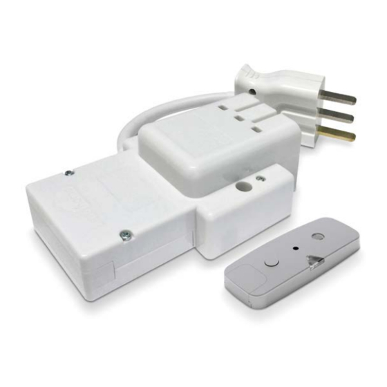
- Page 2 Takk for at du valgte komfyrvakten Innohome SGK4000 Komfyrvakten overvåker og analyserer koketoppens temperatur og endringen av den. I en farlig situasjon avgir komfyrvakten en alarm og slår av koketoppen. Varmesensoren er plassert over koketoppen. Styringsenheten kobles til koketoppens strømuttak. INNHOLD I PAKKEN: •...
-
Page 3: Table Of Contents
INNHOLD MONTERING 4-13 Monter varmesensoren ANBEFALT ALTERNATIVT 1a Monter på avtrekkshette 1b Veggmontering 1c Takmontering S. 6-7 S. 8-9 S. 10-11 Monter styringsenheten Funksjontest BRUKSANVISNING 14-21 Begynn å bruke Innohome komfyrvakt Les dette først 16-17 Godt å vite Ved takmontert sensor Etter alarm: Koketopper med mekaniske brytere Etter alarm: Koketopper med touch-betjening Hvis varmesensoren fjernes fra montasjeplaten... -
Page 4: Montering
MONTERING Monter komfyrvakten Følg nøye anvisningene for feilfri montering. Monter Monter Funksjontest varmesensoren styringsenheten s. 5-11 s. 12 s. 13... -
Page 5: Monter Varmesensoren
MONTER VARMESENSOR Varmesensorens beste plassering er på avtrekkshette, sentrert midt mellom kokesonene. Sensoren kan også monteres på vegg med brakett eller i taket. Én sensor dekker en inntil 90 cm bred koketopp. Følg anvisningene for feilfri montering. VELG DIN METODE FOR MONTERING ANBEFALT ALTERNATIV T 1a Monter på... - Page 6 AVTREKKSHETTE Velg monteringssted Monter sensoren Mål avstanden fra koketopp til avtrekkshette. Sensoren skal stå sentrert Dersom det er fettfilter i flettet over koketoppen og helst innenfor sone 1 (se tabellen og tegningen). metall, vær sikker på at filteret Den kan godt festes på fettristen. Avstand til lampe er min. 10 cm er fettfritt og tørt.
- Page 7 M O N T E R PÅ AV T R E K K S H E T T E La sensoren romtempereres før montering. Sikringen til komfyren/ koketoppen skal være slått av. Se tabellen for monteringshøyde og følg veiledningen fra 1-4. Sett inn batteriet Still følsomhet Trekk ut batteridekselet og...
- Page 8 VEGG 80 cm Velg monteringssted Monter braketten Monter sensoren Veggmontering krever brakett Brakett med fast vinkel skal mon- Under installasjonen kan senso- som selges separat. Braketter le- teres 80 cm over koketoppen. ren pipe for å varsle at senso- veres med fast og justerbar vinkel ren ikke er ordentlig på...
- Page 9 V E G G M O N T E R I N G M E D B R A K E T T La sensoren romtempereres før montering. Sikringen til komfyren/koketoppen skal være slått av. Se tabellen for monteringshøyde og følg veiledningen fra 1-5. Sett inn batteriet Still følsomhet Trekk ut batteridekselet og...
- Page 10 Måle avstanden! Bytt linsen Velg monteringssted Monter sensoren Løft linsen forsiktig ut med en Sensoren skal plasseres rett over Fjern beskyttelsesfolien fra skrutrekker. Trykk ned IR-linse- koketoppen. Bruk et lodd og en montasjeplaten og plasser den forlengelsen (inkludert i pakken) hyssing for å...
- Page 11 TA K M O N T E R I N G M E D L I N S E F O R L E N G E L S E La sensoren romtempereres før montering. Sikringen til komfyren/koketoppen skal være slått av. Se tabellen for monteringshøyde og følg veiledningen fra 1-5.
-
Page 12: Monter Styringsenheten
STYRINGSENHET 1. Koble fra koketoppens sikring (i sikringsskapet). 2. Koble til styringsenheten mellom koketoppen og strømforsyningen. SIKRING Slå av sikringen Slå av kurssikringen til komfyren/koketoppen. Ikke slå på sikringen før sensoren er ferdig innstilt og klar for funksjonstest. Kobling av styringsenhet Koble styringsenheten, se side 24. -
Page 13: Funksjontest
FUNKSJONTEST Monteringen er ferdig når testen er utført. Sensoren vil da gi alarm som kan redde liv og eiendom. Bruksanvisningen, ekstrautstyr og klistremerke skal følge produktet. SIKRING PÅ Slå på sikringen Utfør funksjonstest Aktiver komfyrvakten Trykk og hold inne sensorknap- Slå... -
Page 14: Bruksanvisning
BRUKSANVISNING... -
Page 15: Begynn Å Bruke Innohome Komfyrvakt
BEGYNN Å BRUKE INNOHOME KOMFYRVAKT Platetoppen er klar for bruk 15 minutter etter innstalasjonen er ferdig. Det kan i begynnelsen oppleves alarmer ved normal matlaging. Dette for at sensoren lærer hva som er normal temperaturområde ved matlaging. Hvis komfyrvakten begynner å Må... -
Page 16: Les Dette Først
LES DETTE FØRST Godt å vite Alarmen kan utløses ved bruk av en kjele som er mye mindre enn kokeplaten. Det anbefales å bruke lokk når det er mulig. Dersom stekeovnen også er koblet til komfyrvakten, må også denne slås av når komfyrvakten har løst ut på... -
Page 17: Tiltak Ved Alarm
Tiltak ved alarm BETYDNING TILTAK Sensor Sabotasjealarm Sett sensoren tilbake på montasjeplaten, med lampen vendt mot bruker. 4 pip med 1 sek. intervall Sensoren fjernes fra montasjeplaten. Sensor For-alarm Hvis alarmen ble utløst under vanlig matlaging: Gi sensorknappen et kort trykk mens for-alarmen Korte pip med få... -
Page 18: Innstillinger
INNSTILLINGER Øke/redusere følsomheten Følsomhetsnivået til varmesensoren stilles inn manuelt ved takmontering, veggmontering og når avtrekkshetten er høyere enn 60 cm over koke- toppen. For riktig følsomhetsnivå, se tabell på side 7,9 eller 11. 1. Ta ned varmesensoren. Vent til varmesensoren avgir fire pip – koketoppen blir slått av (alarm ved flytting av varmesensor). 2. -
Page 19: Første Innstilling Av Følsomheten
Sjekk følsomheten Stille følsomhetsnivået tilbake til fabrikk- 1. Ta ned varmesensoren. (Vent innstillingen til sensoren avgirn fire pip og koketoppen blir slått av.) Ta ned varmesensoren. (Vent til sensoren avgirn fire pip og 2. Trykk og hold inne sensor- koketoppen blir slått av.) knappen (cirka 10 sekunder) til to separate pip høres. -
Page 20: Ofte Stilte Spørsmål
OFTE STILTE SPØRSMÅL Jeg klarer ikke å slå på koketoppen, men det med såpevann. Trykk én gang på sensorknappen. kommer ikke noe signal fra komfyrvakten. Avstill alarmen ved å slå av komfyrens/ SVAR 2: Sensoren har blitt fjernet fra eller er ikke platetoppens sikring (i sikringsskapet) i 15 sekunder. - Page 21 Kontroller at sensoren er riktig montert. Alarmen avstilles ved å trykke inn sensorknap- SVAR 2: SVAR: Se side 6 og utover. pen. Sensorens innstilte følsomhetsnivå vil ikke Hvis sensoren er riktig montert, slår du på endres da espressokannen utløser en alarm for SVAR 3: en kokeplate og utfører en testalarm ved å...
-
Page 22: Komfyrvaktens Tekniske Data
KOMFYRVAKTENS TEKNISKE DATA • Hørbart alarmsignal maks. 80 dB(A) @ 1 m • RF 433 MHz • Patentert teknologi • Oppfyller NEK EN 50615:2015 Standard for komfyrvakter VARMESENSOR Signallampe Lyser grønt ved trykk på sensorknappen. Lyser rødt ved alarm. IR-linse Byttes ved høy montering Sensorknapp Batterideksel... -
Page 23: Garanti
Garanti Samsvarserklæring Vi erklærer under vårt eneansvar at dette I tillegg til den lovbestemte garantien fra forhand- produktet samsvarer med leren har dette produktet en 2 års produsentgaranti som dekker mangler i materiale eller utførelse. • Lavspenningsdirektivet 2014/35/EU Garantien gjelder fra og med kjøpsdatoen. Denne ga- •... -
Page 24: Monter Styringsenheten
MONTER STYRINGSENHETEN 1. Koble fra koketoppens sikring (i sikringsskapet). 2. Koble til styringsenheten mellom koketoppen og strømforsyningen. Til festing på veggen Produsert i Kina INNOHOME OY Itsehallintokuja 4 Polaris Business Park, Castor House FI-02600 Espoo, Finland www.innohome.com... - Page 25 INNOHOME STOVE GUARD SGK4000 PLUG & PLAY U S E R M A N UA L INSTALLATION P. 4-13 USER GUIDE P. 14-21 TECHNICAL SPECIFICATIONS P. 22-24 For indoor use only. Do not use in a professional kitchen. The electrician is not required for installation.
- Page 26 Thank you for choosing Innohome Stove Guard! Innohome Stove Guard is a safety product for domestic kitchens. The Stove Guard consists of a state-of-the-art Heat Sensor that monitors the cooker from the top, and a Control Unit that cuts the power if a dangerous situation occurs. The Control Unit is installed behind the cooker or inside the kitchen cabinet next to the cooker.
- Page 27 CONTENTS INSTALLATION 4-13 Installation of the Heat Sensor RECOMMENDED OPTIONAL 1a Installation under cooker hood 1b Wall mounting 1c Ceiling mounting P. 6-7 P. 8-9 P. 10-11 Installation of the Control Unit Function test USER GUIDE 14-21 Getting started with Innohome Stove Guard Read before using Innohome Stove Guard 16-17 Avoiding false alarms...
-
Page 28: Installation
INSTALLATION Installing the Stove Guard To install correctly, follow the instructions. STEP 1: STEP 2: STEP 3: Installation of Installation of Function test the Heat Sensor the Control Unit p. 5-11 p. 12 p. 13... -
Page 29: Installation Of The Heat Sensor
INSTALLATION OF THE HEAT SENSOR The recommended place to install the Heat Sensor is directly above the centre of the cooker, under the cooker hood. The Heat Sensor can also be mounted on a wall with a mounting bracket or on the ceiling. Follow these instructions for correct installation. - Page 30 COOKER HOOD Select the mounting location Mount the Heat Sensor Measure the installation height. The Heat Sensor should be centred The Heat Sensor might beep at above the cooker, preferably within Zone 1 (see the diagram below). this stage indicating that it is not It can be attached to the grease filter.
- Page 31 I N S TA L L AT I O N U N D E R CO O K E R H O O D Allow the Heat Sensor to reach room temperature before use. The power to the cooker must be switched off (at the consumer unit). See the table below for the mounting location and follow instructions 1-4.
- Page 32 WALL 80 cm Select the required location and mount the bracket Mount the Heat Sensor Wall mounting requires a bracket (SAI1000-FBx), sold separately. The The Heat Sensor might beep at bracket is fastened on the wall using adhesive tape or screws. this stage indicating that it is not properly placed on the installa- See the mounting instructions in the bracket package.
- Page 33 WA L L M O U N T I N G W I T H B R A C K E T Allow the Heat Sensor to reach room temperature before use. The power to the cooker must be switched off (at the consumer unit). See the table below for the mounting location and follow instructions 1-5.
- Page 34 CEILING Measure distance! Replace lens Finding the mounting Mount the Heat Sensor position Carefully lift the lens with a The Heat Sensor might beep at screwdriver. Press down the this stage indicating that it is not Measure the distance between IR lens extension (included) properly placed on the installa- the cooker and ceiling.
- Page 35 C E I L I N G M O U N T I N G W I T H I R L E N S E X T E N S I O N Allow the Heat Sensor to reach room temperature before use. The power to the cooker must be switched off (at the consumer unit).
-
Page 36: Installation Of The Control Unit
CONTROL UNIT 1. Disconnect cooker fuse (on the main electricity board). 2. Connect the Control Unit between the cooker and its power supply. POWER Disconnect the power Switch off the power at the consumer unit. Do not turn on the Note! Consumer unit before the Heat Sensor is set and ready for a... -
Page 37: Function Test
FUNCTION TEST The installation is completed when the test has been passed. The Heat Sensor will then give an alarm. This user manual, accessories and stickers should be left with the product for future reference. POWER Return the power Perform function test Reset the alarm Switch on the power at the Wait 30 seconds after switching... -
Page 38: User Guide
USER GUIDE... -
Page 39: Getting Started With Innohome Stove Guard
GETTING STARTED The cooker is ready for use 15 minutes after completing the installation of the Stove Guard. However, at the beginning, it may start to signal during normal cooking. This is because the Heat Sensor learns what the normal temperature ranges are during cooking. The Heat Sensor may start Press the button to indicate that The Heat Sensor has then learned... -
Page 40: Read Before Using Innohome Stove Guard
READ BEFORE Avoiding false alarms Use a pan that covers the entire hotplate to prevent false alarms. Using a lid is recommended. Always use the cooker hood if you have one. If you have a freestanding cooker or an oven under the hob, the oven controls must also be turned off once the power supply to the cooker or hob has been switched off by the alarm. -
Page 41: Action In The Event Of An Alarm
Action in the event of an alarm The cooker will automatically be ready for use after the Stove Guard has detected that the hazardous situation is over, and all the controls are set to “0”. See the alarm overview below for actions. SOUND MEANING MEASURES... -
Page 42: Other Settings
OTHER SETTINGS Change the sensitivity level Due to differences in kitchen environments, the sensitivity level of the Heat Sensor may have to be set manually. 1. Remove the Sensor from the installation plate The Heat Sensor emits 4 “beeps” ( ). -
Page 43: Checking The Sensitivity Level
Checking the Reset the Heat Sensor sensitivity level to factory settings 1. Remove the Sensor from the Remove the Sensor from the installation plate. (The Sensor installation plate. (The Sensor gives gives 4 “beeps” ( ) and the 4 “beeps” ( ) power is cut off cooker is switched off.) to the cooker). -
Page 44: Frequently Asked Questions
FREQUENTLY ASKED QUESTIONS 1. I cannot turn on the cooker, and there is no Make sure that the Heat Sensor is firmly ANSWER 1: signal from the Control Unit. attached to the installation plate and that it is The Sensor has been removed or placed positioned correctly. - Page 45 cooking, and should not give an alarm too easily. The test is recommended when retrofitting the Note! Therefore, the Stove Guard only emits an alarm when cooker and ceiling-mounted Sensor. a certain temperature (or rate of temperature rise) 11. The Heat Sensor gives an alarm when I make is detected, but still long before a real risk situation.
-
Page 46: Technical Specifications
TECHNICAL SPECIFICATIONS • Alarm signal 80 dB(A) @ 1 m • RF 433 MHz • Patented technology • Fulfils NEK EN 50615:2015 Standard for stove guards (Eurofins Expert Services Oy) THE HEAT SENSOR Signal LED should face towards use IR lens (Lens extension for high installations) Button... -
Page 47: Warranty
Warranty EU Declaration of Conformity In addition to the statutory warranty from the As the product's manufacturer, we declare under our retailer, this product has a 2-year manufacturer’s sole responsibility, that this product corresponds to: warranty covering defects in materials or execution. •... -
Page 48: Cooker Connection
COOKER CONNECTION 1. Disconnect cooker fuse (on the main electricity board). 2. Connect the Control Unit between the cooker and its power supply. For attaching to the wall Manufactured in China INNOHOME OY Itsehallintokuja 4 Polaris Business Park, Castor House FI-02600 Espoo, Finland www.innohome.com...
Need help?
Do you have a question about the STOVE GUARD SGK4000 and is the answer not in the manual?
Questions and answers