
Subscribe to Our Youtube Channel
Summary of Contents for Optimus DA-4PM/0F2
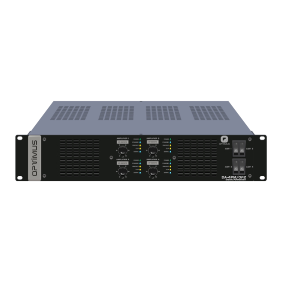
- Page 1 Chassis for 4 power amplifiers DA-4PM/0F2 F2 and F2DC series DA-4PM/0F2 version 1.0...
- Page 2 Note: The information provided in this manual does not include details of design, production or equipment variations. Nor does it include possible hazardous situations during installation, operation or maintenance. If you need special assistance beyond the manual, please contact our technical service. DA-4PM/0F2 version 1.0...
-
Page 3: Table Of Contents
5.1. RSAP-F2 module music program audio input ..................11 5.2. Surety paging relay of module RSAP-F2 ....................13 TECHNICAL CHARACTERISTICS ....................... 14 6.1. DA-4PM/0F2 ............................14 6.2. RSAP-F2 .............................. 14 6.3. Amplifier modules ..........................15 DOCUMENT VERSION TRACKING ......................15 CERTIFICATE OF GUARANTEE ........................ -
Page 4: Description
The F2DC series amplifiers can be powered either at 100- The F2 series amplifiers are powered at 100-240VAC 240VAC 50/60Hz through the DA-4PM/0F2 chassis, or at 50/60Hz through the DA-4PM/0F2 chassis. 24VDC via an individual power strip for each amplifier module. -
Page 5: Rear Panel
5b) (Only if RSAP-F2 module is available) AMPLIFIER 1 surety paging relay. 5c) (Only if you have the RSAP-F2 module) Volume of the auxiliary program input (PROGRAM INPUT). 5d) (Only if RSAP-F2 module is available) AMPLIFIER 1 auxiliary program input. DA-4PM/0F2 version 1.0... -
Page 6: Connection
10% above the rated power of the amplifier. The DA-4PM/0F2 constantly monitors the status of the speaker line output. If a short-circuit is detected on the speaker line, the front LED PROTECT and the yellow LED on the rear RJ45 of the corresponding amplifier flash. -
Page 7: Audio Input Connection
The connection between pin 8 and the shield of the RJ45 connector to the amplifier GND, and the Shielding: connection between the amplifier GND and the DA-4PM/0F2 chassis, is made through the internal jumpers JP1 and JP2. If the installation requires it due to noise caused by ground loops, you can separate these connections by modifying the position of these jumpers. - Page 8 4. Replace the equipment cover and reconnect the power supply. Figure 7 CONNECTION OF THE SHIELD AND PIN 8 AMPLIFIER GROUND CONNECTION OF THE RJ45 CONNECTOR TO GND OF TO DA-4PM/0F2 CHASSIS THE AMPLIFIER CONNECTED CONNECTED (FACTORY SETTING) (FACTORY SETTING) SEPARATE SEPARATE DA-4PM/0F2 version 1.0...
-
Page 9: Activating The Standby Mode Of The Amplifier
STANDBY CONTROL 4.4. Mains connection The DA-4PM/0F2 has a 100-240VAC power input. Use the power cable supplied with the equipment to connect it to the mains. Before connecting, make sure that the mains voltage matches the requirements of the equipment. -
Page 10: 24Vdc Secondary Power Supply (Only F2Dc Series Amplifiers)
AMPLIF. 1 Figure 10 In the F2DC series amplifiers, the 24VDC secondary power input is protected by a blade-type fuse. The DA-4PM/0F2 is supplied with a spare fuse for each amplifier module of the F2DC series. Attention: The fuse value varies depending on the amplifier model, as shown in the table below:... -
Page 11: Accessory Module Rsap-F2
JP1. If the installation requires it due to noise caused by ground loops, you can separate this connection by changing the position of Shielding: jumper JP1 as shown in figure 13 on the following page. DA-4PM/0F2 version 1.0... - Page 12 2. Remove the two screws holding the RSAP-F2 module and pull the module out until the jumper JP1 is visible. 3. Configure jumper JP1. 4. Re-insert the module and connect the power supply. Figure 13 CONNECTION OF THE SHIELD AND PIN 8 OF THE RJ45 CONNECTOR TO GND OF THE AMPLIFIER CONNECTED (CONFIGURATION FACTORY) SEPARATE DA-4PM/0F2 version 1.0...
-
Page 13: Surety Paging Relay Of Module Rsap-F2
Figure 14 shows an example of AV series attenuators connection with surety paging (3-wire speaker lines) and figure 15 with CV series attenuators (4-wire speaker lines). Figure 14. Figure 15. CONNECTION OF AV SERIES ATTENUATORS CONNECTION OF CV SERIES ATTENUATORS WITH SURETY PAGING WITH SURETY PAGING DA-4PM/0F2 version 1.0... -
Page 14: Technical Characteristics
Slots for amplifier modules F2 series amplifiers: Full range 100-240VAC 50/60Hz (via DA-4PM/0F2). Power supply F2DC series amplifiers: Full range 100-240VAC 50/60Hz (via DA-4PM/0F2) and 24VDC (separate power input for each amplifier). Front volume potentiometer (independent for each amplifier). Controls Front ON/OFF switch (independent for each amplifier). -
Page 15: Amplifier Modules
520W (Max.) 7. DOCUMENT VERSION TRACKING Reference system Type of Document Confidentiality DA-4PM/0F2 Installation and operation guide Date Modifications Content Written by: May 2022 Version R+D Department Approved By Function Date Ferran Gironès i Puig R+D Director 05/2022 DA-4PM/0F2 version 1.0... -
Page 16: Certificate Of Guarantee
In the event that the guarantee rights do not to present the original purchase invoice or the guarantee certificate. apply, OPTIMUS S.A. shall duly inform the client. If, within a period of 6 weeks from this communication, no written repair order is received from the client 2. - Page 19 Chasis para 4 etapas de DA-4PM/0F2 potencia series F2 y F2DC DA-4PM/0F2 versión 1.0...
- Page 20 Nota: La información proporcionada por este manual no incluye detalles de diseño, producción o variaciones en el equipo. Tampoco incluye posibles situaciones de riesgo durante la instalación, funcionamiento o mantenimiento. Si usted necesita asistencia especial más allá del manual, por favor contacte con nuestro servicio técnico. DA-4PM/0F2 versión 1.0...
- Page 21 5.1. Entrada de audio de programa musical del módulo RSAP-F2 .............. 11 5.2. Relé de seguridad de avisos del módulo RSAP-F2 ................13 CARACTERÍSTICAS TÉCNICAS ......................... 14 6.1. DA-4PM/0F2 ............................14 6.2. RSAP-F2 .............................. 14 6.3. Módulos amplificadores........................15 DOCUMENT VERSION TRACKING ......................15 CERTIFICADO DE GARANTÍA ........................
-
Page 22: Descripción
Los amplificadores de la serie F2 se alimentan a 100- tanto a 100-240VAC 50/60Hz a través del chasis del DA- 240VAC 50/60Hz a través del chasis del DA-4PM/0F2. 4PM/0F2, como a 24VCC mediante una regleta individual para cada módulo amplificador. -
Page 23: Panel Posterior
5b) (Sólo si dispone del módulo RSAP-F2) Relé de seguridad de avisos del AMPLIFICADOR 1. 5c) (Sólo si dispone del módulo RSAP-F2) Volumen de la entrada auxiliar de programa (PROGRAM INPUT). 5d) (Sólo si dispone del módulo RSAP-F2) Entrada auxiliar de programa del AMPLIFICADOR 1. DA-4PM/0F2 versión 1.0... -
Page 24: Conexión
10% por encima de la potencia nominal del amplificador. El DA-4PM/0F2 supervisa constantemente el estado de la salida de línea de altavoces. En caso de detectar cortocircuito en la línea de altavoces, el LED frontal PROTECT y el led amarillo del RJ45 posterior del amplificador correspondiente parpadean. -
Page 25: Conexión De La Entrada De Audio
La unión entre el pin 8 y el apantallamiento del conector RJ45 a GND del amplificador, y la unión Blindaje: entre el GND del amplificador y el chasis del DA-4PM/0F2, se realiza a través de los puentes internos JP1 y JP2. Si por ruidos causados por bucles de masa la instalación lo requiere, puede separar estas uniones modificando la posición de estos puentes. - Page 26 Figura 7 UNIÓN DE LA PANTALLA UNIÓN DE MASA DEL Y PIN 8 DEL CONECTOR RJ45 AMPLIFICADOR A GND DEL AMPLIFICADOR AL CHASIS DEL DA-4PM/0F2 UNIDO UNIDO (CONFIGURACIÓN DE FÁBRICA) (CONFIGURACIÓN DE FÁBRICA) SEPARADO SEPARADO DA-4PM/0F2 versión 1.0...
-
Page 27: Activación Del Modo Standby Del Amplificador
CONTROL 4.4. Conexión a la red eléctrica El DA-4PM/0F2 dispone de una entrada de alimentación de 100-240VAC. Utilice el cable de alimentación suministrado junto al equipo para conectarlo a la red eléctrica. Antes de conectarlo, asegúrese de que la tensión de red coincide con los requisitos del equipo. -
Page 28: Alimentación Secundaria A 24Vcc (Sólo En Amplificadores De La Serie F2Dc)
En los amplificadores de la serie F2DC, la entrada de alimentación secundaria de 24VCC está protegida mediante un fusible de tipo cuchilla. Junto al DA-4PM/0F2 se entrega además un fusible de recambio por cada módulo amplificador de la serie F2DC. -
Page 29: Módulo Accesorio Rsap-F2
JP1. Si por ruidos causados por bucles de masa la instalación lo requiere, puede separar esta unión modificando la posición del puente Blindaje: JP1 tal y como indica la figura 13 de la página siguiente. DA-4PM/0F2 versión 1.0... - Page 30 3. Configure el puente JP1. 4. Inserte de nuevo el módulo y conecte la alimentación. Figura 13 PUENTE JP1 UNIÓN DE LA PANTALLA Y PIN 8 DEL CONECTOR RJ45 A GND DEL AMPLIFICADOR UNIDO (CONFIGURACIÓN DE FÁBRICA) SEPARADO DA-4PM/0F2 versión 1.0...
-
Page 31: Relé De Seguridad De Avisos Del Módulo Rsap-F2
AV (líneas de altavoces de tres hilos) y la figura 15 con atenuadoras de la serie CV (líneas de altavoces de cuatro hilos). Figura 14. Figura 15. CONEXIÓN DE ATENUADORES SERIE AV CONEXIÓN DE ATENUADORES SERIE CV CON SEGURIDAD DE AVISOS CON SEGURIDAD DE AVISOS DA-4PM/0F2 versión 1.0... -
Page 32: Características Técnicas
Unidades de altura Rack 19” Peso (sin amplificadores) 6,5 Kg 6.2. RSAP-F2 Relé de Seguridad de Avisos 8A / 240VAC Alimentación A través del DA-4PM/0F2 Consumo (máximo) 75mA 1 Entrada de programa, mediante conector RJ45. Entradas de audio Sensibilidad: 0dB (775 mV RMS) Controles Potenciómetro de volumen de programa. -
Page 33: Módulos Amplificadores
520W (Max.) 7. DOCUMENT VERSION TRACKING Reference system Type of Document Confidentiality DA-4PM/0F2 Installation and operation guide Date Modifications Content Written by: May 2022 Version R+D Department Approved By Function Date Ferran Gironès i Puig R+D Director 05/2022 DA-4PM/0F2 versión 1.0... -
Page 34: Certificado De Garantía
Los productos sin derechos de garantía sólo se repararán contra pago de los OPTIMUS S.A. se reserva el derecho de cargar el coste adicional de estos compo- gastos por el cliente. En caso de ausencia de derechos de garantía, OPTIMUS S.A.
Need help?
Do you have a question about the DA-4PM/0F2 and is the answer not in the manual?
Questions and answers