Table of Contents
Advertisement
Quick Links
VS102 Electronic Vibration Switch
VS102 Electronic Vibration Switch
User Manual
Installation, Operation, Maintenance
ProvibTech, Inc.
11011 Brooklet Drive, Suite 300, Houston, Texas 77099, USA
Phone: +1-713-830-7601, Fax: +1-281-754-4972, Email:
pvt@provibtech.com
, Web:
www.provibtech.com
ProvibTech
Phone: +1-713-830-7601 Fax: +1-281-754-4972
,
pvt@provibtech.com
www.provibtech.com
0
VS102-USR-E-C-5
COPY RIGHT PROVIBTECH 2008
Advertisement
Table of Contents

Related Manuals for Provib Tech VS102

Summary of Contents for Provib Tech VS102
- Page 1 VS102 Electronic Vibration Switch VS102 Electronic Vibration Switch User Manual Installation, Operation, Maintenance ProvibTech, Inc. 11011 Brooklet Drive, Suite 300, Houston, Texas 77099, USA Phone: +1-713-830-7601, Fax: +1-281-754-4972, Email: pvt@provibtech.com , Web: www.provibtech.com ProvibTech Phone: +1-713-830-7601 Fax: +1-281-754-4972 pvt@provibtech.com www.provibtech.com...
-
Page 2: Table Of Contents
VS102 Electronic Vibration Switch Table of Content VS102 Electronic Vibration Switch - Introduction..................... 2 Specifications..............................2 Physical................................2 System Default Setting ............................3 VS102 System Installation............................4 Installation - Mechanical Outline Drawing......................4 Installation – Hardware............................5 ... -
Page 3: Vs102 Electronic Vibration Switch - Introduction
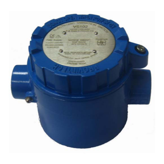
VS102 Electronic Vibration Switch VS102 Electronic Vibration Switch - Introduction The VS102 Electronic Vibration Switch is designed to be the cost effective solution for vibration switch applications. The VS102’s unique rugged design suitable harsh environments and hazardous areas. It has a universal mounting feature, relays or triacs, and a 4-20mA output. -
Page 4: System Default Setting
VS102 Electronic Vibration Switch System Default Setting Channel Type: default is Acceleration Alarm latching**: default is latching input, velocity output. Alarm: dual dry contact relays; single dry Transducer type: internal piezoelectric contract relays; dual TRIAC NO; dual accelerometer TRIAC NC; single TRIAC NO; single Transducer location: internal TRIAC NC;. -
Page 5: Vs102 System Installation
VS102 Electronic Vibration Switch VS102 System Installation Installation - Mechanical Outline Drawing Supply Note: The default case has no local Reset. ProvibTech Phone: +1-713-830-7601 Fax: +1-281-754-4972 pvt@provibtech.com www.provibtech.com... -
Page 6: Installation - Hardware
Installation – Hardware VS102 has two different mounting plates and two different mounting studs. See figuration below. Be aware of that VS102 will sense the vibration in the vertical axis reference to the mounting plate. as shown Mounting plate has two different fixed modes. See figuration below. Default fixed mode is in left figuration. -
Page 7: Installation - Field-Wiring Diagram
VS102 Electronic Vibration Switch Installation – Field-Wiring Diagram Connector Setting: Danger ALERT DANGER Relay NO Remote Reset ARM2 Relay NC Plant Condition Alert System Relay NO ARM1 Relay NC 4-20mA +24V AC 95-250 POWER SUPPLY POWER SUPPLY Factory setting Optional... -
Page 8: Vs102 Operation
Dual SPST Triacs, NO Single SPST Triac, NC Dual SPST Triacs, NC) Power input: VS102 can be configured to work with either high voltage (95 to 250 VAC) or low voltage (22 to 30 VDC). VS102 Zero Set-Point Configuration VS102 can be field configured with zero set-point. -
Page 9: Vs102 Alarm Set-Points Configuration
VS102 Electronic Vibration Switch VS102 Alarm Set-Points Configuration VS102 can be field configured with alarms set-points. Alert Adjust: A) Setup Alarms by Appling Multi-meter. Power on. Connect an ampere meter to the 4-20mA terminal. Hold down RESET/SET button for 10s, OK LED and Alert LED flash and the instrument changes into 4mA calibration mode. -
Page 10: Vs102 Maintenance
VS102 Electronic Vibration Switch VS102 Maintenance Order Information VS102-ABCD-EFGG A: Alarms*** T4@Ta= -40 to +100 ℃ ℃ A = 0: Dual SPDT Relays T6@Ta= -40 to +70 ℃ ℃ A = 1*: Single SPDT Relay PCEC: Ex d ⅡC T4/T6 Gb... - Page 11 VS102 Electronic Vibration Switch GG = 50: 0 –0.5ips rms Note: when user set 4-20mA Outputs item to None, the instrument keeps current output of GG = 51: 0 –1.0ips rms 3mA. GG = 52: 0 –2.0ips rms CAUTION: Due to different regulation and GG = 53: 0 –4.0ips rms...
- Page 12 VS102 Electronic Vibration Switch Mounting Plate , Mounting Studs and Accessories: 165(6.5") 165(6.5") 135(5.3") 135(5.3") 8-R5(0.2") 8-R5(0.2") φ108(4.25") 20(0.79") 8(0.31") 77.7(3.06") 88(3.46") 3/4"NPT or M20×1.5 53.4(2.1") Mounting Mounting 25(0.98") 121(4.76") Holes Holes 5(0.20") 6(0.24") 6(0.24") All dimensions in mm (inches)
-
Page 13: Trouble Shooting
VS102 Electronic Vibration Switch Trouble Shooting The instrument is NOT OK after powered on Inspect whether its power supply is correct referring to the field wiring diagram; inspect whether the delay period expired. The instrument has no 4-20mA output Inspect whether its power supply is correct referring to the field wiring diagram; inspect whether the cables and 4-20mA terminals are connected correctly. - Page 14 VS102 Electronic Vibration Switch Note: If the effect is not apparent, wind the wire around the magnetic ring in a circle as the following figure shows or install another magnetic ring adjacent to the first one as the above figures.
Need help?
Do you have a question about the VS102 and is the answer not in the manual?
Questions and answers