Table of Contents
Advertisement
Quick Links
Advertisement
Table of Contents

Subscribe to Our Youtube Channel
Related Manuals for ALIEN WELD XT200

Summary of Contents for ALIEN WELD XT200
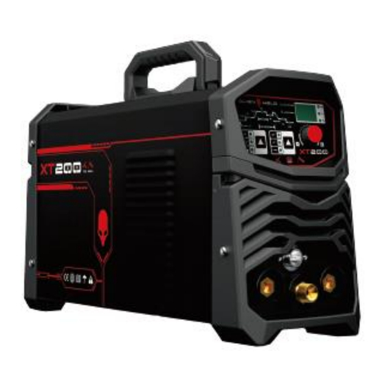
- Page 1 MODEL: TIG HIGH FREQUENCY / MMA OPERATORS’ MANUAL IMPORTANT: Welcome to use the Alienweld XT200 welding machine. Read This Owner's Manual carefully before attempting to use this equipment. Used correctly, can prolong the service life of the arc welding machine!
-
Page 2: Table Of Contents
CONTENT 1. SAFETY ....................................... 1 1.1 SIGNAL EXPLANATION ..................................1 1.2 ARC WELDING DAMAGE ................................1 1.3 INSTALLATION, OPERATION AND MAINTANCE NOTICES ....................4 1.4 THE KNOWLEDGE OF ELECTRIC AND MAGNETIC FIELDS ...................... 5 2. ARC WELDING MACHINE INTRODUCTION ..........................6 2.1 DEVICE BRIEF INTRODUCTION ................................ -
Page 3: Safety
1. SAFETY 1.1 Signal Explanation The above signals mean warning! Notice! Running parts and getting an electric shock or thermal parts will take damage for your body or others. The corresponding notices are as follows. It is quite a safe operation after taking several necessary protection measures. - Page 4 Don't use the dilapidated, damaged, small sized and bad contact cables. ⚫ Don't twine the cables on your body. ⚫ If you touch one electrode of the workpiece、ground or equipment, please don’t touch the another electrode. ⚫ Keep the equipment in good condition, timely maintain or replace the damaged parts, make regular ⚫...
- Page 5 Let your head away from dust, do not inhale the dust. ⚫ If indoors, keep good ventilation, or use exhaust device to drive the smoke and gas that produced by welding. ⚫ Read relevant safety data material, follow the manufacturer’s introduction and suggestions for metals, ⚫...
-
Page 6: Installation, Operation And Maintance Notices
1.3 Installation, operation and maintenance notices FIRE OR EXPLOSION MAY CAUSE DANGEROUS! Don’t place and install the equipment in the fuel and flammable surface or nearby. ⚫ Don't make the power cord overload, ensure that the specifications of power supply system, load rate are not ⚫... -
Page 7: The Knowledge Of Electric And Magnetic Fields
1.4 The knowledge of electric and magnetic fields Electric current flowing through any conductor causes localized Electric and Magnetic Fields (EMF). The discussion on the effect of EMF is ongoing all the world. Up to now, no material evidences show that EMF may have effects on health. -
Page 8: Arc Welding Machine Introduction
2. ARC WELDING MACHINE INTRODUCTION This operation manual is suitable for the inverter DC pulsed (non-pulsed) TIG/MMA machine. 2.1 Brief introduction This series welding machine adopts the latest pulse width modulation (PWM) technology and insulated gate bipolar transistor (IGBT) inverter technology, which can realize TIG operation and change work frequency to medium frequency so as to replace the traditional hulking work frequency transformer with the cabinet medium frequency transformer. -
Page 9: Working Principle
2.2 Working Principle The working principle of THIS- series welding machines is shown as the following figure. Single phase work frequency AC 220V or 230V (50 Hz) is rectified into DC (about 300V), then is converted to medium frequency AC (about 40-60KHz) by inverter device (IGBT), after reducing voltage by medium transformer (the main transformer) and rectifying by medium frequency rectifier (fast recovery diode), and is outputted by inductance filtering. -
Page 10: Installation And Adjustment
3. INSTALLATION AND ADJUSTMENT 3.1 Parameters Type Parameter Input voltage 1 phase,220~230V±10%,50/60Hz Rated input current(A) 16.4 26.4 33.5 40.6 Rated input power(KW) Power factor 0.80 Maximum no-load voltage (V) 62~64 62~64 Welding current range(A) 5~160 5~180 5~200 5~220 Efficiency ≥80% 160A 40%... - Page 11 Type 200/250 Parameter 1 phase, 1 phase, 1 phase,110V±10%, 1 phase,220V±10%, 110V±10%, 220V±10%, Input voltage 50/60Hz 50/60Hz 50/60Hz 50/60Hz Rated input current(A) 33.5 25/28 42/48 Rated input power(KWA) 5.5/6.2 9.2/10.5 Power factor 0.80 Maximum no-load voltage (V) 62~64 62~64 Welding current range(A) 5-145 5-160 5-145...
-
Page 12: Duty Cycle & Over Heat
3.2 Duty cycle and overheat Duty cycle, also called load duration rate, use “X” stands for. It’s defined as the proportion of the time that a machine can work continuously within a certain time (10 minutes). The rated duty cycle means the proportion of the time that a machine can work continuously within 10 minutes when it outputs the rated welding current. -
Page 13: Equipment Connection(Tig/Mma
3.3 Equipment Connection (TIG) TIG TORCH SWITCH POWER CABLE CONNECTOR TIG TORCH CONNECTOR EARTH CLAMP GAS OUTLET CONNECTOR CONNECTOR POWER SWITCH GAS OUTLET CONNECTOR Workpiece is connected to the output positive electrode of welding machine, and welding torch is connected to ⚫... - Page 14 (MMA) POSITIVE CONNECTION NEGATIVE CONNECTION EARTH CLAMP ELECTRODE EARTH CLAMP ELECTRODE HOLDER HOLDER Workpiece is connected to the output negative electrode of welding machine, and welding torch is connected to ⚫ the positive electrode, which is called DC NEGATIVE CONNECTION; otherwise, that is called DC POSITIVE CONNECTION.
-
Page 15: Operation Introduction
4. OPERATION INTRODUCTION 4.1 Layout for the front panel 6 7 8 9 10 11 12 13 14 Pre flow time 0-1 S Pulse Start current 5-200 A Up slope time 0-5 S Welding current 5-200 A Pulse duty factor 5-100 % (Only pulse machine has This function)... - Page 16 12. Crater current 5-200 A 13. Post flow time 0.1-10 S 14. Pulse duty factor light (Only pulse machine has This function) 15. Time unit 16. Frequency unit High frequency TIG 18. LIFT TIG 19. MMA 20. 2T 21. 4T 22.
-
Page 17: Welding Parameters
4.2 Welding Parameters 4.2.1 Joint forms in TIG/MMA a 对接接头 b 角接接头 c 搭接接头 d T形接头 butt joint b comer joint lap joint T joint 4.2.2 The explanation of welding quality The relation of welding area color & protect effect of stainless steel Argent , Welding area Red-grey... - Page 18 The selective range of Gas nozzle diameter and protective gas flow rate DC Positive Connection Alternating Current Welding current Gas nozzle diameter Gas nozzle diameter range/A Gas flow rate /L·min Gas flow rate /L·min 10~100 4~9.5 4~5 8~9.5 6~8 101~150 4~9.5 4~7 9.5~11...
-
Page 19: Operation Environment
Parameters of piping back sealing welding for mild steel (DCEP) Argon Piping Tungsten Gas nozzle Welding Welding wire Welding flow diameter/m electrode diameter speed diameter/mm current/A voltage/V rate diameter/mm /cm·min /L·min 75~90 11~13 6~8 4~5 75~95 11~13 6~8 4~5 75~100 11~13 7~9 4~5... -
Page 20: Welding Notices
4.4 Operation Notices Read §1 carefully before attempting to use this equipment . ⚫ Connect the ground wire with the machine directly. ⚫ The input power should be single phrase、50-60Hz、220-230V alternating current(AC). ⚫ In case closing the power switch, no-load voltage may be exported. Do not touch the output electrode with ⚫... -
Page 21: Electrical Principle Drawing
5. ELECTRIC PRINCIPLE DRAWIN... -
Page 22: Explosive View
6.EXPLOSION DRAWING Name Name Patch Motherboard Power Switch Bottom Plate Buckle Transformer Solenoid Valve Aviation Socket Bracket Rear Plastic Panel Patch Panel European Fast Socket IGBT Quick Connector Radiator 3 Knob Radiator 1 Front Plastic Panel Fast Recovery Diode Front Panel Radiator 2 Arc-Starting Coil Insulation Board 1...
Need help?
Do you have a question about the XT200 and is the answer not in the manual?
Questions and answers