
Summary of Contents for Scanivalve ZOC 33/64Px
- Page 1 ZOC 33/64Px ZOC 33/64PxX2 Electronic Pressure Scanning Module Instruction and Service Manual...
-
Page 2: Preface
Warranty not to be defective, shall be at the expense of Buyer or the end user, whichever has returned such product or compo- Scanivalve Corporation, Liberty Lake, Washing- nent part. ton, hereafter referred to as Seller, warrants to the Buyer... -
Page 3: Trademarks ® And Copyrights
Packaging for Shipment If the product must be shipped, whether being returned to Scanivalve or relocated to another location it must be packaged properly to minimize the risk of damage. The recommended method of packing is to place the instru-... - Page 4 [INTENTIONALLY LEFT BLANK]...
-
Page 5: Table Of Contents
Table of Contents ZOC33 TABLE OF CONTENTS PREFACE Warnings, Cautions and Notes Warranty Trademarks ® and Copyrights © Packaging for Shipment Important Notice Contact Information Section 1: Specifications General Specifications Environment Specifications Section 2: Introduction General Description ZOC33/64Px ZOC33/64PxX2 ZOC33/64Px - Valveless Thermal Control Unit (ZOCTCU) Section 3: Installation &... -
Page 6: Section 1: Specifications
Section 1: Specifications ZOC33 SECTION 1: SPECIFICATIONS Resolution infinite General Specifications Size (WxHxD) 1.43” x 1.69” x 4.98” Inputs (Px) 64 or 128 (PxX2) (36.42cm x 42.8cm x 126.37cm) Pneumatic Connectors Weight ZOC Px .042” tubulations ZOC33/64Px oz (312g) ZOC Control Pressures 0.063”... - Page 7 Section 1: Specifications Section 1: Introduction ZOC33...
-
Page 8: Section 2: Introduction
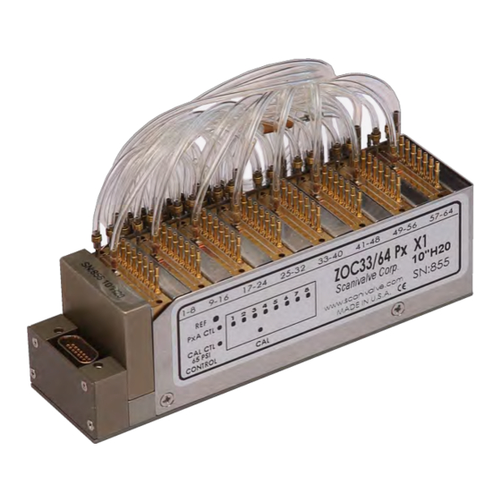
Section 2: Introduction ZOC33 SECTION 2: INTRODUCTION General Description The ZOC33 is an electronic pressure scanner which can accept up to 128 pneumatic inputs. Each ZOC33 module incorporates 64 individual piezoresistive pressure sensors. Each eight pressure sensors are manufactured in a housing designed to facilitate field replacement. -
Page 9: Zoc33/64Px
The output of each sensor is directed to the multiplexer/ amplifier. The channel to be output is selected by a CMOS level binary address supplied by either a Scanivalve data acquisition system or by the customer’s data acquisition system. -
Page 10: Zoc33/64Pxx2
Section 2: Introduction ZOC33 ZOC33/64PxX2 Figure 2.2 depicts a ZOC33/64PxX2, Serial number 398 and earlier. This module contains sixty four (64) pressure sensors in Figure 2.3 depicts a ZOC33/64PxX2, Serial number 399 and eight sensor packs. Each sensor pack contains: later. - Page 11 Section 2: Introduction ZOC33 Figure 2.3 - Current ZOC33/64PxX2 Dimensions [inches(mm)]...
-
Page 12: Zoc33/64Px - Valveless
The output of each sensor is directed to the multiplexer/ amplifier. The channel to be output is selected by a CMOS level binary address supplied by either a Scanivalve data acquisition system or by the customer’s data acquisition system. -
Page 13: Thermal Control Unit (Zoctcu)
Section 2: Introduction ZOC33 Thermal Control Unit (ZOCTCU) An optional Thermal Control Unit (ZOCTCU) (Figure 2.5) is available for applications where temperature swings my be great enough to exceed the compensated range of the sen- sors. Exceeding the compensated temperature range can induce errors in the pressure measurements. -
Page 14: Section 3: Installation & Operation
ZOC cable serviced modules. The ZOC33 may of shipping damage. However, damage can still occur. The be installed into any existing Scanivalve systems without customer must inspect the modules and shipping materials changing configurations. If the ZOC33 is to be used in a for obvious signs of damage. - Page 15 Section 3: Installation & Operation ZOC33...
-
Page 16: Pneumatic Inputs
All Px inputs are .040 inch(1.067mm) bulged tubulations. These tubulations are designed to accept any .042 inch tubing manufactured by Scanivalve Corp. Each sensor pack valve block contains eight (8) or, in the duplex version, sixteen(16) Px inputs. ZOC33 modules are capable of mea- suring pressures up to 50 psid. -
Page 17: Calibration Valve Operation
Section 3: Installation & Operation ZOC33 Purge Mode This mode connects the Px inputs to the pressure sensors and the calibration input. A safe purge pressure can be applied to purge input lines. Isolate Mode This mode isolates the pressure sensors from the Px and calibration lines. -
Page 18: Zoc33 Zoctcu Connectors
Section 3: Installation & Operation ZOC33 ZOC33 ZOCTCU Connectors Table 3.4 - ZOCTCU Pneumatic Inputs Figure 3.7 shows the pneumatic and electrical connectors Channels Connector Tubes Notes on a ZOC33 ZOCTCU. View B shows the electrical connec- 1-64 View A 1-64 tor, View A shows the pneumatic connector for inputs 1-64, PxA CTL... -
Page 19: Sensor Installation
(2) If necessary, remove the valve from the sensor housing. in the field is possible but not recommended without prior This should be done only if tubing restrictions do not allow training from Scanivalve. If a sensor must be replaced, the sensor pack to be pulled. follow these instructions. - Page 20 Section 4: Electronic Components ZOC33 [INTENTIONALLY LEFT BLANK]...
-
Page 21: Section 4: Electronic Components
Section 4: Electronic Components ZOC33 SECTION 4: ELECTRONIC COMPONENTS Amplifier Board The amplifier board receives an millivolt input from the channel selected by the multiplexer. The signal is ampli- fied to a nominal 2.5 Vdc full scale and output through the decoder board to the I/O connector. -
Page 22: Multiplexer Board
Section 4: Electronic Components ZOC33 Multiplexer Board The multiplexer receives millivolt input signals from each of the sensors. It also receives inputs from the decoder board Each eight (8) channel sensor pack has its own combina- which select the channel to be output to the amplifier tion multiplexer and excitation board. -
Page 23: Decoder Board
Section 4: Electronic Components ZOC33 Decoder Board The data system outputs an address for a channel to be read. The address is sensed by the decoder board and The decoder board is the main circuit board in the ZOC33. converted to an address and enable output. The enable All of the sensor packs and the amplifier plug into this line selects the sensor pack and the address line selects board. - Page 24 Section 4: Electronic Components ZOC33 Figure 4.5 - ZOC33 Decoder Board Connector Pinouts...
- Page 25 Section 4: Electronic Components ZOC33...
- Page 26 ZOC33 [INTENTIONALLY LEFT BLANK]...
- Page 27 ZOC33 1722 N. Madson St. Liberty Lake, WA 99019 Phone: 1-800-935-5151 1-509-891-9970 Fax: 1-509-891-9481 scanco@scanivalve.com www.scanivalve.com ZOC33 Service Manual March 16, 2016...
Need help?
Do you have a question about the ZOC 33/64Px and is the answer not in the manual?
Questions and answers