Table of Contents

Summary of Contents for RHEINTACHO rotas CR
- Page 1 Operating Instructions Programmable Speed Monitor rotas CRRA • • • RHEINTACHO Messtechnik GmbH Tel. +49 (0)761 45 13 - 0 Waltershofener Straße 1 Fax +49 (0)761 44 52 74 79111 Freiburg sales@rheintacho.de Germany www.rheintacho.com...
- Page 2 The device is state of the art. It meets the legal requirements of the EC. 2002 All rights reserved. The contents of this booklet including data, statements and drawings for the application and operation of the device are protected by copyright and may not be reproduced in any form whatsoever without the prior written permission of the manufacturers.
- Page 3 The Purpose of this booklet These Operating Instructions are essential for the safe application and operation of the Programmable Speed Monitor (hereafter referred to as the 'device'). It is essential that the safety notes and operational sequences contained in the manual are strictly observed, non-compliance with any of these could cause danger to personnel and damage to machinery.
-
Page 4: Table Of Contents
Contents: 1. Safety Limits of application Assembling, electrical connections, programming and operation If problems occur Maintenance and warranty Disposal and recycling Explanation of symbols 2. Description of the device and its functions Technical features Monitoring modes Principle of measurement 3. Identification Package contents Labelling 4. -
Page 5: Safety
1. Safety 1.1 Limits of application The safety notes and operational sequences described in this manual must be understood and observed by all personnel using the device. The device is designed only for building into a control box. Assembly and operational criteria described in 'Technical data' (Section 7) must be observed in all respects. -
Page 6: If Problems Occur
Operation and programming should be by personnel who have been trained to perform these activities and who are authorized by the factory management. Information regarding the safe handling of the device can be found in sections 3 to 6 of this manual. 1.3 If problems occur A watchdog is controlling all device functions. -
Page 7: Explanation Of Symbols
1.6 Explanation of symbols The following symbols are to warn or advise, they appear adjacent to the certain parts of the text to emphasize the relative importance of that item. DANGER! Potential for injury or death. ATTENTION! Potential for damage to the device or application. INFORMATION! Critical to the correct functioning of the device -43-... -
Page 8: Description Of The Device And Its Functions
2. Description of the device and its functions 2.1 Technical features Figure 1 Basic circuit diagram Power supply (Figure 1, In 1, ' Power supply U Depending on the model, the device will require 18 to 36 V DC or, with a built-in DC/DC converter, 10 to 36 V DC. Signal input (Figure 1, In 3) The device disposes of a variable signal input: Three types of signals (PNP, NPN and Sine) and the Trigger... - Page 9 However the device is prepared to process signals of two-wire sensors as well as three-wire sensors. Input (Figure 1, In 2, 'Active starting-bridge') A pulse signal of > 2.5V activates the Starting-bridge. This condition is maintained until the pulse signal drops below 1V and until the programmed Starting-bridge Time has elapsed.
-
Page 10: Monitoring Modes
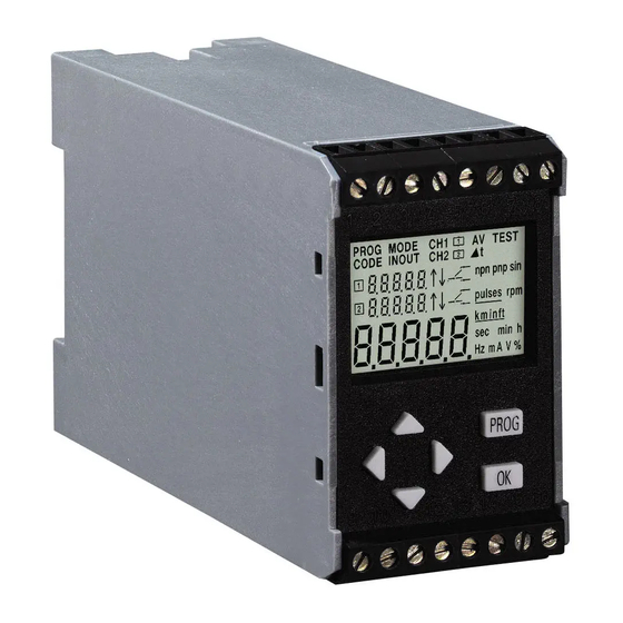
Figure 2 Front face of the device The six key control panel (Figure 2, item 1) The six keys allow simple programming of all functions. The display (Figure 2, items 2 to 8) During the monitoring mode the LCD display shows: Item 2. - Page 11 Over-speed monitoring The active relay switches to the alarm mode if the upper set speed limit is exceeded. When the speed drops back below the switch back value and when the switch back time delay has expired, the relay switches back to the normal phase.
-
Page 12: Principle Of Measurement
Switch back value Set value Activation of the Starting-bridge Starting-Bridge time Figure 4 Under speed monitoring and controlling Scope The models CRR and CRRA are capable of monitoring simultaneously over-speed and under-speed. 2.3 Principle of measurement The signal frequency at the signal input is modified by measuring a number of frequency periods to give an average figure. - Page 13 A typical example would be to measure the pulse period variations over a complete revolution of the machine and then take the average. Step-width 1P/200 Hz Figure 5 Acceptable number of periods allowed for averaging ATTENTION! The system is calculating an average value after each measurement time.
-
Page 14: Identification
3. Identification 3.1 Package contents When delivered the package will contain: A Speed Monitor to specification ordered This Operating Instruction booklet 3.2 Labeling There are two labels on the exterior of the device that show the following data: Model Code −... - Page 15 3.3 Variants Model Output Analogue Power supply Part number output 1 Relay without 18…36 V DC 5810.100 2 Relays without 18…36 V DC 5810.200 1 Relay with 18…36 V DC 5820.100 CRRA 2 Relays with 18…36 V DC 5820.200 1 Relay without 10…36 V DC/DC 5813.100...
-
Page 16: Assembly And Electrical Connections
4. Assembly and electrical connections ATTENTION! Possible impairment of the device function! To ensure correct functioning, the device should only be operated within the conditions described in Section 7, 'Technical Data'. The switching delay of the relay outputs subsequent to detection of under or over speed, is governed by the number of periods required to determine an average value. - Page 17 DANGER! Danger voltage! Before any wiring connections are made to the relays of the device, the relays must be in power down positions and the power supply switched off. The relay contacts must both operate at the same voltage. Examples: NOT allowed: Relay 1 with mains voltage (230 V) and relay 2 with low voltage (24 V) Allowed: Relay 1 and relay 2 with mains voltage (230 V)
- Page 18 Terminal Type CR Types CrxA and CRRx CRxA = CRA and CRRA CRRx = CRR and CRRA Input NPN/PNP/Sine Sensor supply 0 V (GND) Sensor supply 12 V Starting-bridge (+) Starting-bridge (-) FREE CRxA: Analogue output Power supply U DC (+) Power supply U DC (-) Relay 1 no...
-
Page 19: Procedure At Start-Up
5. Procedure at start-up The device has three modes: Monitoring mode. See Section 5.1. − Test mode. See Section 5.2. − Programming mode. See Section 5.3. − ATTENTION! Before using the device, check that its specification is correct for the application and that, if required, it has been correctly programmed. -
Page 20: Test Mode
5.2 Test Mode ATTENTION! Potential for inadvertent switching! When the Test mode is activated, the relay will switch if the system is currently running at a level outside the parameters for which the device is programmed. Monitoring Mode = measuring value*1,15 = Measuring value*0,85... -
Page 21: Programming Mode
5.3 Programming mode Assuming that a customer has not specified programming at the factory, the device will be delivered with the standard default settings as shown in Table 3. No. Parameter Default values Access User code 00000 Signal processing Unit* No. - Page 22 The programming mode is started by pressing the 'PROG' key. Programming stages There are three programme stages, the programming steps referred to below are described In Section 6: The first stage establishes the User Code (see Table 3); it covers steps 1 to 5. The second stage programmes the Standard Functions;...
-
Page 23: Programming
6. Programming INFORMATION! When the Programme Mode is entered and pre-set parameters are changed, these settings should be noted and retained on file, for future reference. Programming / Abort Confirm Selection Setting numerals Figure 8 The programming keyboard INFORMATION! Refer to the fold-out diagram of the of the programming path for assistance during programming. - Page 24 Enter user code or PROG. INFORMATION! At the first time of programming for standard devices, (i.e. not customized by the factory) the code will read '00000'; this may be left, in which case ignore steps 3 & 4. The mode is accessible until another code is entered during steps 3 or 4 at which time the display changes to '- - - - -' therefore the new code must be noted.
- Page 25 ATTENTION! The number of pulses per unit governs the maximum limiting value when monitoring speed. If the existing number is changed, the existing limiting values must be checked during steps 10 & 10’. The number of pulses per unit must always be entered except when the selected unit is Hz.
- Page 26 Set the decimal point for the measuring range. The position of the decimal point defines the resolution of the measuring range. Set the limiting value of Relay 1. ATTENTION! Potential for system malfunction! The limiting value must be lower than the maximum value governed by the number of pulses per unit (see step 7).
- Page 27 Special function 'Switch back delay' is only programmable on Relay 1. This ist the point at which the alarm phase is entered. Set the monitoring direction of Relay 1. Monitoring over-speed is indicated by an up arrow (↑). Monitoring under-speed is indicated by a down arrow (↓).
- Page 28 Setting the optional Relay 2 Steps 10’ to 13’ are the same as 10 to 13 carried out for Relay 1. Set the relay value for Relay 2. Set the monitoring direction of Relay 2. Set the contact position for relay 2. Set the switch back value of relay 2.
- Page 29 Start the programme path 'Special functions' pressing the left and right arrows simultaneously (instead of step 16). Set the Switch Back delay time. This function is only used for over speed monitoring in combination with Relay 1. Setting range is 0.00 to 99.9 seconds. Set the Starting-bridge time.
- Page 30 Set the trigger level of the signal input: Based on the programmed type of signal done in the programming step “Set type of signal input” the software of the device proposes a value. On principle the trigger level should be selected as high as possible to provide high disturbance resistance.
-
Page 31: Technical Data
7. Technical data 7.1 Operational Data Speed monitoring Range 0,01Hz…20 000 Hz Accuracy < +/- 0,03% of final value +/- 1 Digit Temperature coefficient < +/- 0,01% of final value Switch delay < 20 ms + measuring time (see page 65) Power supply UB Voltage 18...36 V DC... - Page 32 Min. interpulse period 25 μs „Active starting-bridge“ input Trigger level 2,5 V...36 V; U < 1,0 V high Relay outputs Number 1 or 2 (optional) Type Change-over contacts Switching voltage AC: ≤ 250 V (!!! Safety note sect. 4.2) DC: ≤ 42 V Nominal switching current AC: 5 A DC: 2 A...
-
Page 33: Operating Conditions
7.2 Operating Conditions Operating temperature -25°C...+70°C (LCD-Display -10°…+70°C) -13°C...158°F (LCD-Display+14°...+158°F) Storage temperature -25°...+85°C -13...185°F Relative humidity Max. 95 % not condensing Protection (IEC 529) IP 20 Vibration (IEC 68-2-6) 0,7 g @ 1...100 Hz Protective class Protective insulation EMV Norms Disturbance resistance: EN 61326-1;... -
Page 34: Mechanical Data
7.3 Mechanical Data Casing type Normal rail case (for 35 mm mounting rail EN 50 022) Casing dimensions 43 * 70 * 114 (mm; W*H*D) Casing material GFK, polycarbonate (inflammability class UL94-V-0) Terminals 16 screw clamps with tension contacts Connection cross section 1 * 2,5 mm2 1 * 1,5 mm2 with end sleeve for strands...
Need help?
Do you have a question about the rotas CR and is the answer not in the manual?
Questions and answers