Table of Contents
Advertisement
Quick Links
Advertisement
Table of Contents

Summary of Contents for Triol TM01
- Page 2 Dear Customer! Thank you for purchasing Triol TM01 Downhole Measuring System, the key to your successful oil production strategy. We are sure that our Downhole Measuring System technologies will allow you to advance and maximize your production. TM01 is complete with the following manuals: ...
- Page 3 Copyright © Triol Corporation Ltd. 1993-2020 All rights reserved. No part of this publication may be reproduced or copied without prior written permission from Triol Corporation Ltd. All products and company names mentioned in this manual are trademarks or registered trademarks of their respective holders.
-
Page 4: Table Of Contents
CONTENTS List of abbreviation and warning indicators ..................5 Triol blocks compatibility ........................6 Safety requirements ......................... 7 Description ............................9 Surface Card description ......................9 Surface Board description......................13 Surface Panel description ......................16 High-Voltage Choke IP56 description ..................19 High-Voltage Choke Flexible description .................. -
Page 5: List Of Abbreviation And Warning Indicators
List of abbreviation and warning indicators Abbreviation: TM01 – Downhole Measuring System SB – Surface Board SP – Surface Panel SC – Surface Card TM01-XXi – Downhole Intake Sensor TM01-XXd – Downhole Discharge Sensor HVC – High-Voltage Choke ESM – Electric Submersible Motor ESP –... -
Page 6: Triol Blocks Compatibility
Surface unit Downhole unit Add. equipment TM01-05 When connecting the TM01-09 secondary winding of the "Delta" transformer, TM01-10 Triol High-Voltage Triol Surface Board ST TM01-15 Choke IP56 or Triol Board TM01-20 High-Voltage Choke TM01-25 Flexible (without filter) TM01-28 is used... -
Page 7: Safety Requirements
Safety requirements The safety requirements for the control, operation, maintenance and repair of the system must comply with the Occupational Health and Safety Management Systems (BS OHSAS 18001:2007), Safety Rules for Operation of Customers’ Electrical Installations, Rules for Safety in the Oil and Gas Industry, and Inter-industry Rules on Labor Safety. - Page 8 Safety recommendation The Downhole Measuring System must be installed, adjusted, and serviced by qualified electrical maintenance personnel. Improper installation or operation may cause injury to personnel or damage to equipment. The Downhole Measuring System must be installed and grounded in accordance with local and national electrical codes.
-
Page 9: Description
Description Surface Card description Surface Card (IP20 enclosure) is designed for inside the VSD installation. Figure 2 – Surface Card Surface Card specification with all parameters, operating conditions, and overall dimensions: Table 1 – Surface Card specification Input/Output parameters Rated voltage 24VDC +10, -20% Power consumption, not more than Duration mode... - Page 10 There are indicators and various signs on the Surface Card, the description of which are given below. Figure 3 – Surface Card (front view) Description of the elements of the Surface Card: Power – Surface Card powered Sensor – communication available / no communication with downhole sensor R ins –...
- Page 11 Figure 4 – Surface Card (bottom view) Description of the elements of the block Surface Card: 1. Interface port (RS-232, RS-485) 2. Dout port (Dout1, Dout2) 3. Supply port (24VDC) 4. Output port (supply downhole sensor) To switch on Surface Card, it is necessary to supply power to the unit. Table 2 shows the possible status indications on the Surface Card.
- Page 12 Table 2 - Description of LED indicators on the Surface Card Status Description Power 24VDC power applied no 24 VDC power applied Sensor there is no communication failure with downhole (green) sensor there is communication failure with downhole sensor (red) R ins insulation resistance/current leak measurements data transmission from downhole sensor...
-
Page 13: Surface Board Description
Surface Board description The Triol Surface Board ST, LF, DG (IP20 enclosure) is designed for inside the VSD installation. The Surface Board offers RS-485 and RS-232 Modbus ports as standard. Figure 5 - Surface Board Surface Board specification with all parameters, operating conditions, and overall dimensions: Table 3 –... - Page 14 There are indicators and various signs on the Surface Board, the description of which are given below. Figure 6 – Surface Board Description of the elements of the Surface Board: Heating – heating work R ins. – insulation resistance measurement Sensor –...
- Page 15 Table 4 - Description of LED indicators on the Surface Board Status Description R ins. When power is applied to the SB, all LEDs Sensor are turned on for 5 seconds. Checking the health of Power LEDs R ins. The SB is not powered or the power Sensor supply in the SB is faulty Power...
-
Page 16: Surface Panel Description
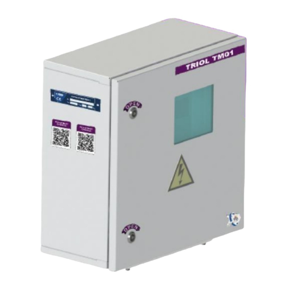
Surface Panel description The Triol Surface Panel (IP56 enclosure) shows information on the display for operators to read and process data in real time relating to the fluid parameters and parameters of the submersible equipment. The SP offers an RS-485 Modbus port as standard. Digital and analog I/O are optional. - Page 17 There are indicators and various signs on the SP, the description of which are given below. The layout of the SP controls is shown in figures 8 and 9. Figure 8 – Surface Panel (front view)
- Page 18 QF1 circuit breaker according to the wiring diagram. The Surface Panel can exchange data with the upper level via an RS-485 interface using one of the following protocols: Triol, TriolAK, and Transfer. Description of the protocols are presented in Appendix C.
-
Page 19: High-Voltage Choke Ip56 Description
High-Voltage Choke IP56 description Triol High-Voltage Choke IP56 provides a zero “wye” point when the transformer is connected in «delta» mode. Figure 10 High-Voltage Choke High-Voltage Choke specification with all parameters, operating conditions, and overall dimensions: Table 6 – High-Voltage Choke specification... -
Page 20: High-Voltage Choke Flexible Description
High-Voltage Choke Flexible description Triol High-Voltage Choke Flexible (IP56, IP65, IP00) provides a zero “wye” point when the transformer is connected in «delta» mode. Figure 11 High-Voltage Choke Flexible High-Voltage Choke specification with all parameters, operating conditions, and overall dimensions: Table 7 –... -
Page 21: Connection And Configuration
Connection and configuration Triol Surface Card Connection The Surface Card is installed in the control station (VSD / VFD) on a 35mm DIN rail. Apply power to the Surface Card at the "supply port" 24VDC We recommend connecting the Surface Card to SCADA via RS-485, according to the diagram in Figure 12. - Page 22 Table 8 – Surface Card port pinout Port name Port pin Pin name 1 – RS-485 A Interface port 2 – RS-485 B 3 – NC 4 – NC 5 – 0V RS-232/485 6 – 0V RS-232/485 7 – RS-232 RxD 8 –...
-
Page 23: Surface Card Menu Description
Surface Card menu description Surface Card menu structure Description of the "Sensor data" menu Upper setpoint value Measured parameter value: value within set point value is out of the set point Lower setpoint value Unit of measurement Indication of the change of the measured parameter in comparison with the previous value:... - Page 24 Parameter menu description 1 – Display of the current value of the measured parameter, indication of the change in comparison with the previous value. By pressing (Enter), buttons select unit measurement, - confirm the change, - cancel. 2 – Time and date display. 3 –...
- Page 25 Description of the main menu 1 – Displaying the current state of the system: - Wi-Fi connection status: - external device connected, - external device not connected - USB Flash connection status: - device recognized (event log reading completed), - device not recognized (reading event file not completed), - device not connected - the state of the digital outputs: - the parameter is linked to the digital output within the...
-
Page 26: Starting Up A Surface Card
To configure recording by time, go to the "Events log" menu. It is recommended to set the "TM recording period" parameter for blocks according to Table 9. Table 9 – The recommended set period for recording in the event log. Downhole sensor TM recording period, s TM01-05 TM01-10 TM01-15 TM01-20 TM01-25 To read the log onto a flash drive, you must specify the well number in the "Settings"... -
Page 27: Setting Wi-Fi
To connect to the device, you need to find a device named “Triol XXXXX” on your smartphone in the Wi-Fi menu, where XXXXX is the well number. Enter the Wi-Fi password, which can be found on the website www.trilcorp.eu. - Page 28 You can navigate through the menu of all settings in the same way as on the Surface Card.
-
Page 29: Triol Surface Board
Triol Surface Board Connection RS-485 RS-485 AC INPUT RS-232 GND – ground 0-SUT Heating Mounting Mounting "0"-SUT R ins (or Sensor Power holes holes current GND – leakage) ground Figure 13 – Surface Board description Table 10 – Pin assignment of RS-232, RS-485 Surface Board Interface Connectors... -
Page 30: Surface Board Testing
Surface Board testing For a test option with HV Choke and Intake sensor, you need to connect the VSD or automatic control system through pins interface board connectors Test unit TM01 RS-485/232 Out 220V 0-SUT “0-SUT” Connector HV Choke... - Page 31 Surface Board testing procedure using TM01 Test Unit To check the Surface Board with the downhole sensor simulator, it is necessary to assemble the connection diagram according to Figure 16. In this test mode, the Test Unit is used as a controller. Connect with Test Unit off.
- Page 32 Figure 17 - Position of the switches to select a mode Table 11 - Switch 1 Position Parameter Value Switch position (Left) 4309kOhm ±5% R Insulation resistance (when the switch position is “4309kOhm” of the Imitator) 9999kOhm ±5% R Insulation resistance (when the switch position is “9999kOhm”...
-
Page 33: Starting Up A Surface Board
Starting up a Surface Board Supply voltage to Surface Bboard. "Rins.", "Sensor", and "Power" indicators must light up for 5 seconds to check the health of the LEDs. The “Power” indicator always indicates the presence of power on the Surface Board. Then the “Sensor” indicator turns off, “Rins.” and “Power”... - Page 34 2 – ON “Transfer” (ability to set speed and 3 – OFF address) 4 – OFF 1 – ON 2 – OFF «Triol» 3 – OFF 4 – OFF 3 – OFF Temperature oil motor 3 – ON Temperature winding...
- Page 35 To operate the VSD controller with the Surface Board, the controller must set the data transfer rate via RS-485/RS-232 to 19.2kB, select the data transfer protocol corresponding to the protocol selected on the Surface Board, and also set the address in SC 68 (0x44). Pinout RS-232 and RS-485 interfaces are listed in Table 10 of the operation manual.
-
Page 36: Triol Surface Panel
Triol Surface Panel Connection RS-232 output RS-485 output open-end wrench 10mm (3/8”) Network 0-SUT Extreme inclusion of a surface panel Mounting eyes outside the rack (0,394”) (0,67”) Figure 19 – Surface Panel connection... -
Page 37: Surface Panel Testing
It is prohibited to disconnect and connect detachable joints during voltage supply. It is prohibited to disconnect and connect detachable joints if supply voltage is available. Surface Panel testing RS-485/232 TM01 Test Unit 0-SUT Out 220V “0-SUT” Connector HV Choke Intake Figure 20 –... -
Page 38: Starting Up A Surface Panel
Starting up a Surface Panel Supply the voltage to the Surface Panel. Turn on the QF1 circuit breaker. The operation of the “R ins.”, “Sensor”, and “Power” indicators is described above; see the starting process for the Surface panel. Wait 1-2 minutes after switching on and check the static and dynamic data readings. -
Page 39: Setting Event Log Recording
1. Protocol: - Transfer - Triol - Triol AK - Apergy 2. Exchange rate: - 2.4kB - 4.8kB - 9.6kB - 19.2kB - 38.4kB - 57.6kB - 76.8kB - 115.2kB 3. Network address: 1…247. 4. Stop bit: 1, 2. Setting event log recording The event log is configured in the “Event log”... -
Page 40: Setting Up Analog Outputs (If Included)
Setting up analog outputs (if included) To configure the analog outputs, you must go to the menu “Downhole sensors” → “AOUT8 setup”. In the menu "AOUT8 setup" all parameters measured by the Downhole Measuring System are indicated, namely: Actual Rins ... -
Page 41: Triol High-Voltage Choke
Triol High-Voltage Choke Connection General view Figure 23 – HVC description Socket SP16 2 pin IP68 Plug Figure 24 – HVC connection... - Page 42 Mounting eyes (0.394”) (0.67”) Figure 25 – HVC mounting...
-
Page 43: Installation Of Surface Equipment On Shelving
Installation of surface equipment on shelving The Surface Panel and High-Voltage Choke are installed on the shelving of a surface unit. You can install the High-Voltage Choke and Surface Panel together and install the unit separately. There is a certain order for installing the shelving and equipment on it. Figure 26 - Shelving with the Surface Panel and High-Voltage Choke, general view Initially, the shelving is disassembled in a package with the surface unit, with the following parts: 9 racks, screws M8x25 DIN 933 A2-80, washer 8 DIN 7980, washer 8 DIN 125 –... - Page 44 Installation instructions for the shelving: Install the shelving according to the figures below. Figure 28 – The shelving installation instructions...
- Page 45 Instructions for installing equipment on the shelving: 1. Install Surface Panel on the shelving. ATTENTION Until the Surface Panel wiring is complete do not install the High- Voltage Choke, since installation / connection of the Surface Panel is not possible when the High-Voltage Choke is already installed. 2.
-
Page 46: Troubleshooting
Troubleshooting Diagnostics flow charts This section describes the following Downhole Measuring System failure diagnostics: 1. Telemetry indicators are not active Surface Card indicators are not active Surface Board indicators are not active Surface Panel indicators are not active 2. Missing telemetry data on the controller of the control station 3. - Page 49 If the problem persists, go to the next item "The downhole sensor does not transfer data to SC/SB/SP"...
- Page 54 Figure 30 – Indication of the controller UMKA-04...
-
Page 55: Fuse Replacement Instructions For High-Voltage Choke
Fuse replacement instructions for High-Voltage Choke 1. To replace the fuse, remove the protective glass: - unscrew 8 screws (in Figure 31, highlighted in green) - remove the protective glass. 2. Remove the 2 screws that secure the fuse holder that has failed (Figure 31, highlighted in yellow for HVC IP56, Figure 32 for HVC Flexible). - Page 56 3. Unscrew the fuse holder as shown in Figure 33. Figure 33 – Loosening the fuse holder 4. Remove the fuse from the holder according to Figure 34. Figure 34 – Removing a failed fuse 5. Install a new fuse in the holder as shown in Figure 35. Figure 35 –...
- Page 57 6. Screw on the holder as shown in Figure 36. Figure 36 – Screwing the holder 7. Reinstall the fuse holder and protective glass...
-
Page 58: Storage
Storage TM01 and its components (spare parts) must be stored in a sealed packing. To prevent damage during storage, avoid exposure to corrosive gases and vapors. Storage conditions of TM01-25 must correspond to the climate: • storage temperature from -40 to +75°C (from -40 to 168°F) •... - Page 59 APPENDIX A Surface Card Modbus map Protocol Link Level Possible data transfer rate – 9600, 19200, 38400, 57600, 115200 baud. Default value 19200 baud, 8-N- Protocol Application Level 1 The basis of the protocol – Modbus RTU. 2 Supported protocol Modbus RTU function: 03 –...
- Page 60 SC input register tables Table A.5 Parameter Address, Initial number The name of the parameter, Attachment Notes Data width value at units (offset) power up 0х2000 reserve … … reserve 0х2004 DS exchange protocol number 0х2005 DS software version number static data format - a single...
- Page 61 Table A.6 Parameter Address, The name of the parameter, Initial value number Attachment Notes units at power up (offset) 0х2100 Insulation resistance, kOhm 15000 0x2101 Current leak, mA … … reserve 0х2104 Service information 0х2105 Frame type 0х2106 reserve 0х2107 reserve 0х2108 SB exchange protocol number...
- Page 62 Motor winding temperature, °С Motor oil temperature, °С reserve X axis vibration, m/s Y axis vibration, m/s Z axis vibration, m/s Discharge pressure, MPa Annulus pressure, MPa Discharge temperature, °С (TM01-15, TM01-25) Table A.8 Parameter Initial Address, Attachment number The name of the parameter, units...
- Page 63 APPENDIX B Surface Board Modbus map Protocol Link Level Possible data transfer rate – 9600, 19200, 38400, 57600, 115200 baud. Default value 19200 baud, 8-N- Protocol Application Level 1 The basis of the protocol – Modbus RTU. 2 Supported protocol Modbus RTU function: 03 –...
- Page 64 SB input register tables Table B.5 Parameter Address, Data Initial value number The name of the parameter, Attachment Notes width at power up units (offset) 0х2000 reserve … … reserve 0х2004 DS exchange protocol number 0х2005 DS software version number static data format –...
- Page 65 Table B.6 Parameter Address, The name of the parameter, Initial value number Attachment Notes units at power up (offset) 0х2100 Insulation resistance, kOhm 1500 … … reserve 0х2104 Service information 0х2105 Frame type 0х2106 reserve 0х2107 reserve 0х2108 SB exchange protocol number 0х2109 SB software version number Format - a single...
- Page 66 Temperature winding motor, °С Temperature oil motor, °С reserve X axis vibration, m/s Y axis vibration, m/s Z axis vibration, m/s Pressure discharge, MPa Annulus pressure, MPa Temperature discharge, °С (TM01-15, TM01-25) Table B.8 Parameter Initial Address, Attachment number The name of the parameter,...
- Page 67 Apergy Modbus map Table B.10 № Data width Description Units 40129 Serial Number High 40130 Serial Number Low 40131 Packet Time Stamp High Seconds 40132 Packet Time Stamp Low Seconds 40133 Packet Count High 40134 Packet Count Low 40135 Intake Pressure Psia °F 40136...
- Page 68 APPENDIX C Surface Panel Modbus map (UMKA-04) Transfer Modbus map Table C.1 - Transfer Modbus map Modbus Data № Description Units Transfer Transfer Function width 8196 2004 DS protocol number 8197 2005 DS software version 8198 2006 DS factory number (low) 8199 2007 DS factory number (high)
- Page 69 Table C.2 - Triol Modbus map & Triol AK Modbus map Modbus Data № Triol Triol Description Units Triol Triol Function width 00BD 0380 DS protocol number 00BE 0381 DS software version 00BF 0382 DS model code 00C0 0383 DS factory number (low)
- Page 70 Table C.3 - Apergy Modbus map № Data width Description Units 40129 Serial Number High 40130 Serial Number Low 40131 Packet Time Stamp High Seconds 40132 Packet Time Stamp Low Seconds 40133 Packet Count High 40134 Packet Count Low 40135 Intake Pressure Psia °F...
- Page 71 APPENDIX D TM01 technical drawings Surface Card Figure D.1 – Surface Card drawing...
- Page 72 Surface Board Figure D.2 – Surface Board drawing...
- Page 73 Surface Panel Figure D.3 – Surface Panel drawing...
- Page 74 High-Voltage Choke IP56 Figure D.4 – HVC IP56 drawing...
- Page 75 Figure D.5 – HVC IP56 drawing...
- Page 76 High-Voltage Choke Flexible Figure D.6 – HVC Flexible drawing...
- Page 77 Figure D.7 – HVC Flexible drawing...
- Page 78 Shelving for installing Surface Panel and High-Voltage Choke IP56 It is possible to install shelving AT.305142.455 for mounting the Surface Panel and High- Voltage Choke. The shelving can be installed on a concrete panel. There are holes in the legs of the shelving with a diameter of 14mm / 0.55in (number of holes - 8 pc.) for the anchor mounting.
- Page 79 Figure D.9 – The shelving drawing...
- Page 80 APPENDIX E SB External Connections Figure E.1 – SB external connections...
- Page 81 SP External Connections Figure E.2 – SP external connections * - additional options...
- Page 82 SC External Connections Figure E.3 – SC external connections...
- Page 83 APPENDIX F SB/SP system connection diagram System with High-Voltage Choke (connecting a delta transformer) Figure H.1 – System connection diagram with the HVC (transformer delta connection) Figure H.2 – System connection diagram without the HVC (wye transformer connection)
- Page 84 APPENDIX G SC system connection diagram Figure G.1 – Surface Board connection diagram with the HVC flexible (transformer delta connection Figure G.2 – System connection diagram without the HVC flexible (wye transformer connection...
- Page 85 APPENDIX H Menu structure of the UMKA controller...
Need help?
Do you have a question about the TM01 and is the answer not in the manual?
Questions and answers