Table of Contents
Advertisement
Quick Links
Switcher-2 Assembly guide
Safety warning
The kits are main powered and use potentially lethal voltages. Under no circumstance should someone undertake the
realisation of a kit unless he has full knowledge about safely handling main powered devices.
Please read the "DIY guide" before beginning.
Print or open the following documents :
• Switcher-2 Schematics
• Switcher-2 Components layout
• Switcher-2 Parts list
Follow this guide from item number 1 till the end, in this order. The assembly order is based on components height, from
low to high profile, in order to ease the soldering process : The component you are soldering is always taller than the
previously assembled ones and it is pressing nicely against the work area foam.
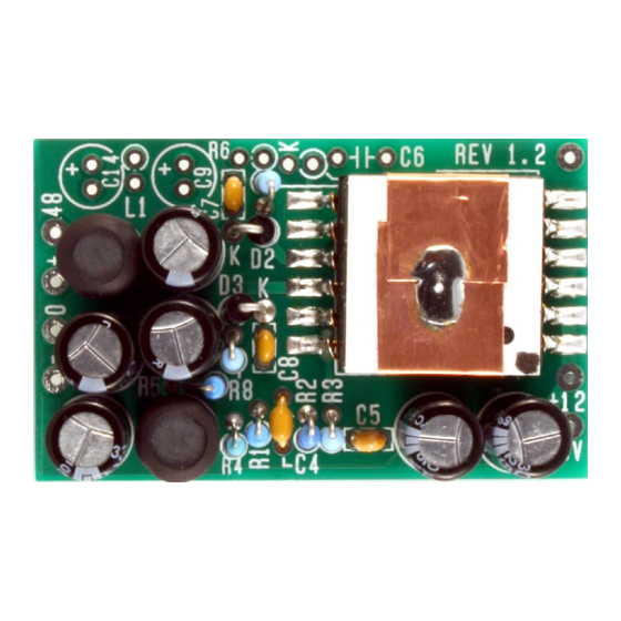
Switcher-2 Assembly guide – Main PCB
1.
Ceramic capacitors
Add C4, C5, C7, C8.
C3 which is placed under the PCB will be installed later.
2.
Resistors
Add R1 to R5 and R8. R7 will be installed later in order to leave an easy access for soldering the
transformer.
The resistors are installed vertically.
Warning
: It is very important to check the resistors value with a DMM because the colour code can be
ambiguous. For example 1K (brown-black-black-brown-brown) can be confused with 110R (brown-brewn-
black-black-brown).
Copyright ©2013 to Today SoundSkulptor
Document revision 1.3 – Last modification : 09/10/14
www.soundskulptor.com
Advertisement
Table of Contents

Related Manuals for Sound Skulptor Switcher-2

Summary of Contents for Sound Skulptor Switcher-2
- Page 1 : The component you are soldering is always taller than the previously assembled ones and it is pressing nicely against the work area foam. Switcher-2 Assembly guide – Main PCB Ceramic capacitors Add C4, C5, C7, C8.
- Page 2 Document revision 1.3 – Last modification : 09/10/14 Switcher-2 Assembly guide – Main PCB Ceramic capacitor C3 Add C3 under the PCB. Cut the leads ultra short. Copper shorted turn In order to reduce the transformer radiations we will add a copper foil turn around the outside of the transformer.
- Page 3 Document revision 1.3 – Last modification : 09/10/14 Switcher-2 Assembly guide – Main PCB LM2586 The LM2586 is soldered on the back side of the PCB. It is a surface mount component with relatively close pins. In order to make the soldering process easier, we are going to cheat a little: Lift pins 4 and 6 (counting from the left) and cut them off.
- Page 4 Document revision 1.3 – Last modification : 09/10/14 Switcher-2 Assembly guide – Main PCB 12. Spacer Stick the rubber spacer on the Switcher3 PCB, at the position shown on the picture, between the solder pads. Switcher-2 Quick testing The switcher can be tested directly in the SK501 module but it is a good idea to check it alone if you can. What you need is a 12V DC source and a voltmeter.
- Page 5 Use a tool with a sharp right angle, like a ruler or an aluminium profile to help position the sides. Place the top side flat on the table (“Sound Skulptor” facing down) and the (A) labelled side at a 90° angle. (A) edge against (A) edge.
- Page 6 Document revision 1.3 – Last modification : 09/10/14 Switcher-2 Assembly guide – Shield Switcher-Shield assembly Warning: This must be done after the switcher has been fully tested in the MC624. Insert the switcher PCB into the shield, making sure the pins position follows the shield top writing.
Need help?
Do you have a question about the Switcher-2 and is the answer not in the manual?
Questions and answers