Table of Contents
Advertisement
Quick Links
Advertisement
Table of Contents

Summary of Contents for Kobold ZFC
- Page 1 Operating Instructions Differential Flow Computer Model: ZFC...
-
Page 2: Table Of Contents
Control panel ..................7 Operator Information and functions ............. 8 Configuration ....................9 How to program the ZFC ..............10 Installation ....................24 General directions ................24 Installation / Surrounding conditions ..........24 ... - Page 3 Manufactured and sold by: Kobold Messring GmbH Nordring 22-24 D-65719 Hofheim Tel.: +49(0)6192-2990 Fax: +49(0)6192-23398 E-Mail: info.de@kobold.com Internet: www.kobold.com Hardwareversion : 03.01.xx Softwareversion : 03.01.xx ZFC K03/0522 page 3...
-
Page 4: Note
Differential Flow Computer model: ZFC 4. Regulation Use Any use of the Differential Flow Computer, model: ZFC, which exceeds the manufacturer’s specification, may invalidate its warranty. Therefore, any resulting damage is not the responsibility of the manufacturer. The user assumes all risk for such usage. -
Page 5: Operating Principle
Flowmeter and temperature input This manual describes the unit with a pulse input from the flowmeter. The ZFC has also a PT100 temperature input. Other versions are available to process (0)4-20 mA signals. Two flowmeters with a passive or active pulse, Namur or sine wave (coil) signal output can be connected to the ZFC. - Page 6 Configuration The ZFC is designed for use in many types of applications. For that reason, a setup menu is available to program the ZFC according to your specific requirements. The setup includes several important features, such as K-Factors, engineering units, signal selection, etc. All settings are stored in a non- volatile memory and therefore kept in the event of a power failure.
-
Page 7: Operation
Take careful notice of the "Safety rules, instructions and precautionary measures" in the front of this manual. This chapter describes the daily use of the ZFC. This instruction is meant for users / operators. Control panel The control panel has three keys. The available keys are:... -
Page 8: Operator Information And Functions
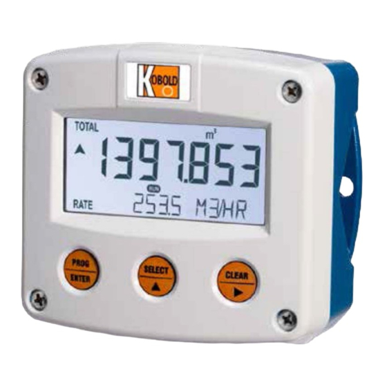
Display calculated differential flow rate and calculated differential total This is the main display information of the ZFC. After the selection of any other information, it will always return to this main display automatically. Total is shown on the upper line of the display and flow rate on the bottom line. When selected in the setup menu, the display shows the flow rate only. -
Page 9: Configuration
The SETUP menu is used to program the ZFC The SETUP menu is accessible at all times while the ZFC remains fully operational. Be aware that in this case any change to the settings may have an influence on the operation. -
Page 10: How To Program The Zfc
ZFC goes back to the related main menu. in the last setting and you navigate to the next setting, the ZFC goes to the related main menu. - Page 11 The explanation assumes that you are in the submenu TOTAL and the setting UNIT. If you do not want to save the change, wait for approximately 20 seconds or press and hold the PROG/ENTER key for approximately 3 seconds. ZFC K03/0522 page 11...
- Page 12 12 DC; 24 DC TEMPERATURE A/B display °C; °F; K no. of wires 2; 3 filter 01 - 99 FORMULA equations type EL (fixed) thermal expansion coefficient 0.000000 - 9.999999 (*10-3/K) normal temperature 0.00 - 99,999.99 K page 12 ZFC K03/0522...
- Page 13 0000000; 111111.1; 22222.22; 3333.333 amount 0.001 – 9999999 COMMUNICATION speed 1200; 2400; 4800; 9600 address 1 - 247 mode bus-rtu; bus-asc; off OTHERS model software version nn:nn:nn serial no. nnnnnnn password 0000 - 9999 tag-nr 0000000 - 9999999 ZFC K03/0522 page 13...
- Page 14 K-Factor. 14 decimals K-factor This setting is used to set the amount of digits behind the decimal point for the K-Factor (A). page 14 ZFC K03/0522...
- Page 15 This setting does influence the update time for the analog output directly. If the output response is too slow, decrease the number of pulses. The shorter the update time, the higher the power consumption of the unit will ZFC K03/0522 page 15...
- Page 16 . A more accurate K-Factor (more decimals, as set in decimals K-Factor) allows for a more accurate operation of the system. decimals K-factor This setting is used to set the amount of digits behind the decimal point for the K-Factor (B). page 16 ZFC K03/0522...
- Page 17 The backlight brightness can be adjusted from 0% (off) to 100% (full brightness) in steps of 20%. When the ZFC is only loop powered, the backlight is disabled. An external power supply is required to supply the backlight. 53 measurement To solve undesired display readings during low or even negative consumption situations, four different measurement methods have been implemented.
- Page 18 62 battery mode The ZFC has two modes: operational or shelf. After "shelf" has been selected, the ZFC can be stored for several years; it will not process the sensor signal; the display is switched off but all settings and totals are stored.
- Page 19 7.1.8 EXPLANATION OF SETUP-MENU 7 - FLOWMETER The ZFC is able to handle several types of input signal. The pickup / signal is selected with: SETUP 71 (Input A), Read also chapter 8 SETUP 72 (Input B), Read also chapter 8.
- Page 20 for petrol is 0.00110 per K. Enter: 1100000. 93 normal temperature Enter here the reference temperature T in degrees Kelvin (K). In most normal applications, the volume has to be calculated at 15°C which is 288,15 K. page 20 ZFC K03/0522...
- Page 21 / decreased with the arrow keys and is directly active. Press ENTER to store the new value. If required, you can program the analog output 'up-side-down'. The 4mA represents the maximum flow rate and the 20mA represents the minimum flow rate. ZFC K03/0522 page 21...
- Page 22 On pulse output R1 a pulse will be sent when the total has increased with the set quantity (SETUP B4). On pulse output R2 a pulse will be sent when the total has decreased with the set quantity (SETUP B4). page 22 ZFC K03/0522...
- Page 23 7.1.14 EXPLANATION OF SETUP-MENU D - OTHERS For support and maintenance it is important to have information about the characteristics of the ZFC. Your supplier will ask for this information when support is required. OTHERS D1 model This setting shows the model name.
-
Page 24: Installation
ZFC is rated for IP65/TYPE 4(X)! When used in very cold surroundings or varying climatic conditions, inside the instrument case, take the necessary precautions against moisture. Mount the ZFC onto a solid structure to avoid vibrations. page 24 ZFC K03/0522... -
Page 25: Installing The Hardware
8.3.1 General installation guidelines In the ZFC, different types of bonding and earthing are used. The common (ground) is mostly used for termination of the wire shields. For V AC applications, the terminal 00 shall not be connected to avoid earth loops. - Page 26 8.3.2 Plastic (GRP) enclosure The PE connection The ZFC in a GRP enclosure meets the requirements of class 2 (double insulated). Therefore the incoming PE wire is terminated with an insulating end cap. Type OR (8-24V AC) Type (8-30V DC)
- Page 27 The sensor supply voltage is selectable: 1.2; 3; 8.2; 12 or 24V DC. Set the sensor supply Make the ZFC safe. If applicable, mind the battery power. Open the ZFC and carefully remove the cable-connectors and the protective cover. Find and set the switches and select the V out as required.
- Page 28 Risk of electrocution - High voltage! Make sure, all the leads to the terminals are disconnected from the ZFC and NEVER connect the mains power supply to the unit when the protection cover has been removed! Type 3 Power supply in: 8-24V AC / 10-30V DC...
- Page 29 (depending on the type of signal). The input signal type has to be selected in the flowmeter setup (read chapter 7). Sine-wave signal (Coil): The ZFC is suitable for use with flowmeters which have a coil output signal. Two sensitivity levels can be selected: COIL-LO: sensitivity from about 80 mV pp ;...
- Page 30 Terminal connections - NPN signal input (typical) Pulse-signal PNP / PNP-LP: The ZFC is suitable for use with flowmeters which have a PNP output signal. 3 V is offered on terminal 11 which has to be switched by the sensor to terminal 10 (SIGNAL).
- Page 31 Terminal connections - Active signal input (typical) Reed-switch: The ZFC is suitable for use with flowmeters which have a reed-switch. To avoid pulse bounce from the reed-switch, it is advised to select REED LP - low-pass filter (read chapter 7).
- Page 32 NAMUR-signal: The ZFC is suitable for flowmeters with an NAMUR signal. With external power supply the 8.2V f o r t h e sensor (terminal 11) can be realized. Terminal connections - NAMUR signal input (typical) Terminal 20-22 and 23-25; Temperature inputs FT - PT100 Two types of PT100 elements can be connected: 2- or 3-wire.
-
Page 33: Problem Solving
9. Problem solving In this chapter, several problems are included that can occur when the ZFC-EL is going to be installed or while it is in operation. Flowmeter does not generate pulses: Check: Signal selection; Pulse amplitude; Flowmeter, wiring and connection of terminal connectors;... -
Page 34: Communication
(4x references are typically used by PLCs), please add a value of 40001 to the Modbus PDU address. E.g. reading the serial number of the product with PLC-based addressing means: 165 + 40001 = register 40166. page 34 ZFC K03/0522... - Page 35 48, 49, 50 [d] 588 [h] 40589 Flow rate-B uint32 0…9999999 0x24C Representation: unit, time, decimals depending on variables 48, 49, 50 40213 Temperature-A [d] 212 [h] uint16 0…9999999 0x0D4 [d] 218 40219 Temperature-B uint16 0…9999999 [h] 0x0DA ZFC K03/0522 page 35...
- Page 36 [d] 33 40034 decimals (A and B) uint16 0…3 [h] 0x021 [d] 34 40035 K-factor uint32 1...9999999 [h] 0x022 Representation: 0.000010…9999999 depending on variable 54: decimals K-factor. [d] 37 40038 decimals K-factor uint16 0…6 [h] 0x025 page 36 ZFC K03/0522...
- Page 37 Representation: 0.000000…9999999 REGISTER VARIABLE TYPE VALUE / REMARKS ADDRESS POWER MANAGEMENT REGISTERS [d] 80 40081 LCD update time uint16 0=fast 2=3sec 4=30sec [h] 0x050 1=1sec 3=15sec 5=off [d] 81 40082 power mode uint16 0=operational 1=shelf [h] 0x051 ZFC K03/0522 page 37...
- Page 38 [d] 128 uint16 0…9999, (0=disabled) [h] 0x080 Representation: 0.000 – 9.999 sec [d] 133 40134 decimals uint16 0…3 [h] 0x085 40131 amount [d] 130 uint32 1...9999999 [h] 0x082 Representation: 0.001…9999999 depending on variables 133 page 38 ZFC K03/0522...
- Page 39 [d] 162 uint32 0…999999 [h] 0x0A2 Representation: nn:nn:nn 40166 serial no [d] 165 uint32 0…9999999 [h] 0x0A5 Representation: nnnnnnn [d] 168 40169 password uint16 0…9999 [h] 0x0A8 40171 tag-nr [d] 170 uint32 0...9999999 [h] 0x0AA Representation: nnnnnnn ZFC K03/0522 page 39...
-
Page 40: List Of Configuration Settings
62 battery mode operate FLOWMETER 71 signal A coil-lo 72 signal B coil-lo TEMPERATURE A/B 81 display unit °C 82 no. of wires 83 filter FORMULA 91 type 92 thermal exp. coefficient 0.000000 93 normal temperature 288.15 K page 40 ZFC K03/0522... -
Page 41: Maintenance
(danger from electrical shock). The housing may only be opened by trained persons authorized by the operator of the facility. Take careful notice of the "Safety rules, instructions and precautionary measures" in the front of this manual. ZFC K03/0522 page 41... -
Page 42: Instructions For Repair
It is the user’s responsibility to take all precautions to dehumidify the internal atmosphere of the ZFC in such a way that no condensation will occur, e.g. to put a dose of desiccant (drying agent) inside the enclosure just before closing it. -
Page 43: Technical Data
Seven 17mm (0.67") and eleven 8mm (0.31"). Various symbols and measuring units. Refresh rate User definable: 8 times/sec - 30 secs. Type ZFC LCD with LED backlight. Good readings in full sunlight and darkness. Power requirements: 12-24V DC + 10% or type PD, PF, PM. Power consumption max. 1 Watt. - Page 44 Units ml; l; m ; mg; g; kg; ton; gal; bbl; lb; cf; rev; - - - - (no unit); scf; nm ; nl; p Decimals 0000000; 111111,1; 22222,22; 3333,333 Time units /sec; /min; /hour; /day page 44 ZFC K03/0522...
-
Page 45: Order Codes
Equations liquid – flow computer for corrected liquid volume. Formel Qnormal = Q * (1 + (Tnormal – T)) where: = thermal expansion coefficient. 14. Order Codes Example: ZFC-K FT 4T 0 3 0 0 Model Enclosure Input Output... -
Page 46: Dimensions
15. Dimensions Housing dimensions ZFC page 46 ZFC K03/0522... -
Page 47: Eu Declaration Of Conformance
16. EU Declaration of Conformance We, KOBOLD Messring GmbH, Hofheim-Ts, Germany, declare under our sole responsibility that the product: Differential Flow Computer Model: ZFC to which this declaration relates is in conformity with the standards noted below: EN 61000-6-2:2005 Electromagnetic compatibility (EMC) - Part 6-2: Generic standards - Immunity for...
Need help?
Do you have a question about the ZFC and is the answer not in the manual?
Questions and answers