
Summary of Contents for Advanced AXIS AX AV-VBM
- Page 1 Audio Panels AV-VBM Audio Panel w/Microphone and AV-VB Distributed Audio Booster Installation, Operation & Programming Manual www.advancedco.com...
-
Page 2: Table Of Contents
Table of Contents Page INTRODUCTION / OVERVIEW ..........................4 ..........................4 RODUCT ESCRIPTION ........................7 ENERAL NSTALLATION OTES FCC ................................7 1.3.1 Emissions ..............................7 INSTALLATION ..............................8 ..............................8 OUNTING AV-VBM AND AV-VB MODULES ........................10 AX-PSU-6 P ......................10 OWER UPPLY HARGER 3.1.1 AX-PSU-6 AC Wiring ..........................10 3.1.2 AX-PSU-6 Battery Circuit Wiring ......................11 3.1.3... - Page 3 6.3.2 AV-VB Interfaced to a Listed (Host) EVAC System (Non Synchronized Independent Messages/Tones) 6.3.3 AV-VBM Interfaced to a Listed (Host) Fire Alarm Control Panel ............41 6.3.4 AV-VBM Interfaced to a Listed (Host) Fire Alarm Control Panel and the AV-VB Distributed Audio Booster (Synchronized Messages/Tones) ......................
-
Page 4: Introduction / Overview
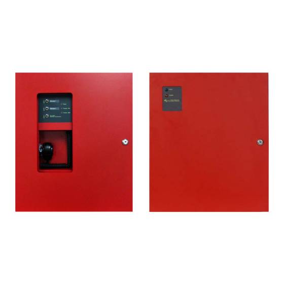
In addition, the AV-VB distributed audio booster can be utilized in an Axis PBUS (RS485) audio installation, supporting sixteen (16) prioritized messages and Advanced “PerfectSync” synchronization. Both the AV-VBM audio panel w/microphone and AV-VB distributed audio booster are designed to provide audio signaling during an emergency situation (alarm, alerts, warnings, mass notification, etc.). - Page 5 AV-AMP-80 AX-PSU-6 Audio Amplifier Module Power Supply Charger Figure 1 – AV-VBM and AV-VB Backbox www.advancedco.com www.advancedco.com...
- Page 6 In addition, the AV-SM switch/LED module provides terminals for host fire alarm control panel monitoring interface. An optional AV-ZS-CM AV splitter switch module is available for installations utilizing the Advanced’ optional AV-ZS amplifier speaker circuit zone splitter module.
-
Page 7: General Installation Notes
1.2 General Installation Notes WARNING: Disconnect all sources of power (AC and WIRING: CHECK that the installation wire sizes are battery) before installing/removing circuit cards or adequate to deliver the required load current and servicing the AV-VBM audio panel w/microphone or AV- maintain compatibility with the specific device operating VB distributed audio booster. -
Page 8: Installation
2 Installation Mount the AV-VBM and/or AV-VB enclosure in a clean, dry, vibration-free area where extreme temperatures are not encountered. The area should be readily accessible with sufficient room to easily install, utilize and maintain the product. Determine the number of conductors required for control and supervision to be installed. Sufficient knockouts (4 double 1 ¾”... - Page 9 Mounting Plate Screws Mounting Plate Screw AV-MIC 6-way Ribbon Cable (AV-VBM Only) Mounting Plate Screws Figure 3 – AV-VBM and AV-VB Module Removal www.advancedco.com www.advancedco.com...
-
Page 10: Av-Vbm And Av-Vb Modules
#14 or #12 AWG (Refer to NEC) FUSE Non-Power Limited Fuse 5A, 250VAC Ceramic, Time Delay (size 5x20mm) (Advanced part number 620-003, Bussmann S505-5-R, Littelfuse 0215005.XP) Over-current protection for this circuit must comply with (HOT/LOAD) Article 760 of the National Electrical Code (NEC) and/or (NEUTRAL) local codes. -
Page 11: Ax-Psu-6 Battery Circuit Wiring
3.1.2 AX-PSU-6 Battery Circuit Wiring AX-PSU-6 Battery Charger Charger current 1.5A (Maximum 45Ah). Supervised, Non-Power Limited. Charging voltage 27.4 VDC typical. Charging temperature compensated. Start the power supply charger on AC power first then connect the batteries. If AC power is not available the power supply charger can be started directly from the batteries. -
Page 12: Ax-Psu-6 Leds
3.1.4 AX-PSU-6 LEDs There are seven (7) onboard LEDs associated with the AX-PSU-6. Refer to the opposite diagram and list below for LED descriptions and purpose. 1. Earth Fault: Illuminates on ground fault (within 10 seconds). 2. Heart Beat: Flashes to indicate proper microprocessor operation. -
Page 13: Av-Amp-80 Audio Amplifier Module
3.2 AV-AMP-80 Audio Amplifier Module The AV-AMP-80 audio amplifier module provides the digital audio capabilities (live voice communications with AV- VBM) of the AV-VBM audio panel w/microphone and AV-VB distributed audio booster and requires 24 VDC nominal power from the AX-PSU-6 (see figure 4). The AV-AMP-80 contains two (2) electrically independent Class “A”... -
Page 14: Av-Amp-80 Wiring
3.2.1 AV-AMP-80 Wiring Class “B” Wiring 4.7K EOL AMP 1 Audio Input Class “A” Wiring AMP 2 Audio Input Microphone Input (Prewired to AV-MIC on AV-VBM) (MIC Supervision Jumper on AV-VB) Trigger Input 1 Trigger Input 2 (Prewired to AV-SM (Prewired to AX-PSU-6 Power Switch/LED on AV-VBM) 24VDC... -
Page 15: Pbus (485) Av-Amp-80 Wiring
3.2.1.1 PBUS (485) AV-AMP-80 Wiring As previously indicated, AV-VB distributed audio boosters can also be configured for use in Axis PBUS (485) amplifier installations. When an AV-VB is utilized in this configuration, the amplifier is wired as a PBUS (485) floor (area) amplifier. -
Page 16: Av-Amp-80 Leds
3.2.2 AV-AMP-80 LEDs There are six (6) onboard LEDs associated with the AV-AMP-80 (see figure 6). 1. Transmit (TX): Flashes when sending data via USB or RS485 port. 2. Heart Beat (HB): Flashes to indicate proper microprocessor operation. 3. Amplifier 1 (AMP 1): On steady when amplifier 1 is active. Flashes on amplifier 1 trouble or open/short circuit on amplifier 1 speaker circuit. -
Page 17: Microphone Wiring (Av-Vbm Only)
3.2.4 Microphone Wiring (AV-VBM only) To allow for live voice communications, the AV-VBM audio panel w/microphone has a 6-way ribbon cable that is prewired from an AV-MIC microphone assembly, located on the AV-VBM inner door, to the AV-AMP-80 audio amplifier module input connector PL2 (see figure 8). This connection not only allows for live voice communications, but also monitors the AV-VBM microphone for both placement and open microphone condition. -
Page 18: Optional Av-Zs Audio Zone Splitter Module
3.2.5 Optional AV-ZS Audio Zone Splitter Module The AV-AMP-80 audio amplifier module is capable of accommodating an optional Advanced AV-ZS audio zone splitter module. The AV-ZS audio zone splitter module is designed to take one or both AV-AMP-80 amplifiers (audio notification appliance circuits) and split these into additional audio notification appliance circuits, each capable of delivering 20 Watts per circuit. -
Page 19: Av-Zs Wiring
Nylon Spacer AMP1 AMP2 Figure 9 – AV-ZS to AV-AMP-80 Mounting 3.2.5.2 AV-ZS Wiring Wire 24 VDC (from AV-AMP-80 power output terminals) to the power input terminals of the AV-ZS audio zone splitter module. Wire one or both AV-AMP-80 amplifiers (audio notification appliance circuits) to the Audio Input 1 and Audio Input 2 terminals of the AV-ZS module and set jumpers J6 and J7 to their appropriate position [1 audio input or 2] (see figure 10). -
Page 20: Av-Zs Speaker Circuit Activation
Figure 10 – Optional AV-ZS Audio Zone Splitter Module Note: For additional information regarding the installation and operation of the AV-ZS audio zone splitter module, refer to AV-ZS Audio Zone Splitter Module Installation Instructions. 3.2.5.2.1 AV-ZS Speaker Circuit Activation The AV-ZS audio zone splitter module speaker circuits are activated by switching the common (COM) of the Input Zone Selection terminal block, through an activation relay contact back to the specific Input Zone Selection (Z1, Z2, Z3, Z4) terminal block for the specific speaker circuit activation. -
Page 21: Optional Av-Zs-Cm Av Splitter Switch Module
Note: Speaker circuit activation is unsupervised; wiring must be within 20 feet of the activation relay contact. When the AV-ZS audio zone splitter module is utilized with a PBUS (RS485) AV-AMP-80 amplifier, the “All” Input Zone Selection must be constantly activate, allowing tracking of the two (2) onboard AV- AMP-80 amplifiers for audio control via the AX-CTL base card PBUS (RS485). -
Page 22: Av-Sm Switch/Led Module (Av-Vbm Only)
3.3 AV-SM Switch/LED Module (AV-VBM only) To allow for control and status of an AV-VBM audio panel w/microphone an AV-SM switch/LED module is provided behind a locked outer door. The AV-SM switch/LED module is the user interface to the AV-VBM audio panel w/microphone. -
Page 23: Av-Sm Switch/Led Operation
3.3.1 AV-SM Switch/LED Operation With proper key access to the AV-VBM audio panel w/microphone inner door, there are three (3) manual user controlled functions that can be performed; Activate Message One (latching toggle switch), Activate Message Two (latching toggle switch) and perform an All-Call live voice page (non-latching toggle switch – hold down to page)[see figure 13]. - Page 24 Power Trouble Figure 15 – AV-RMIC All-Call Remote Microphone The AV-RMIC consists of: AV-MIC-REM: Lockable enclosure (with removable inner and outer doors) and microphone. AV-RM-PCB: Remote microphone module, located in the AV-RMIC, which interfaces to AV-RMI and AV- AMP-80 amplifier (see figure 17). The AV-RM-PCB supervises the AV-RMIC microphone for open circuit, short circuit and disconnection conditions.
- Page 25 AV-RMI Module Mounting Location Figure 16 – AV-RMI Mounting Note: For AV-VBM and AV-VB enclosures manufactured prior to August 2014 an AV-RMI-RP retrofit plate will be required for mounting the AV-RMI remote microphone interface module. www.advancedco.com www.advancedco.com...
- Page 26 Figure 17 – AV-RMIC Wiring www.advancedco.com...
-
Page 27: Recommended Cable Routing
4 Recommended C ble Routing Power limited and non-power limited circuit wiring must remain separate in the cabinet. All power limited circuit wiring must remain at least 0.25” (6.35 mm) away from any non-power limited circuit wiring. Furthermore, all power limited and non-power limited circuit wiring must enter and exit the cabinet through different knockouts and/or conduits (see figure 18). -
Page 28: Av-Vbm And Av-Vb Battery Calculations
5 AV-VBM and AV-VB Battery Calculations Quiescent Load Alarm Load Equipment I (A) Total I (A) Total AV-AMP-80 0.035 = 0.035 0.220 = 0.220 AV-ZS (optional) 0.075 Amplifier 1 Amplifier 2 Total Quiescent Load Alarm Load x 24 hr or 60 hr x 0.0833 Total Quiescent Current Total Alarm Current... -
Page 29: Av-Amp-80 Amplifier Audio Message Programming
6 AV-AMP-80 Amplifier Audio Message Programming To program AV-AMP-80 amplifier messages, you will need the Advanced Axis AV-AMP audio message programming tool (Windows based) version 1.1.4 or higher. 6.1 Installing the Axis AV-AMP audio message programming tool To install the Axis AV-AMP audio message programming tool on your PC, run the program ‘Setup.exe’... -
Page 30: File Menu
6.2.1 File Menu The File Menu contains standard Windows functions such as New, Open, Save and Close. To open a new file, place the mouse cursor over the “New” icon and click. Recent files will be listed in the Recent Files area. -
Page 31: Product View (Description)
6.2.3 Product View (Description) The selected product, AV-VB or AV-VBM, will now be added to the Product View section of the screen. Note: The description associated with the AV-VB or AV-VBM (i.e. AV-VBM) in the Product View can be edited. Simply click on the text and type the label you’d like. -
Page 32: Audio Section 2 - Main Tone/Message
6.2.3.1.3 Audio Section 2 – Main Tone/Message File Name: Is the Audio File name for the message added to Audio Section 2 (i.e.: Female Evac 1. Wav) Repeats: Indicates the number of repeat cycles ( [infinity] to 99) that the Audio Section 2 message will play. When an Audio Selection 2 message is added default is 1, plays Audio Section 2 message once. - Page 33 To add an Audio Section 1 message, navigate to the Audio Files Categories area: Select the Audio File message category required (i.e. “Fire Evacuation”); the following screen will be displayed: Scroll to the required “Fire Evacuation” message, click on the required message and drag it into the “Selected Message”...
- Page 34 If no additional audio sections are required for audio message 1, the following audio message would be placed immediately below the first (1) audio message “Audio Section 1” in the same manner as it was previously done. Again, if the audio message requires a leading tone/message (“Audio Section 1”), a main tone/message (“Audio Section 2”) and a trailing tone/message (“Audio Section 3”).
-
Page 35: Npfa 72 (2013 Edition) Message Requirement
6.2.5.1 NPFA 72 (2013 Edition) Message Requirement 6.2.5.1.1 Example of an NFPA 72 Programmed Message Note: The TNTemporal HighF.wav audio file message plays two rounds, so only 1 repeat is required. 6.2.6 Remove Audio Messages To remove an audio message, select the required message and click on the “Remove Message”... -
Page 36: Moving Messages Up And Down
6.2.7 Moving Messages Up and Down The message order can be changed using the “Move Up” and “Move Down” icon buttons. To move a message up, select the bottom (message 2) message and the “Move Up” icon button will be accessible. Click on the “Move Up” icon button and message two will move to message one location and message one will move to message two location. -
Page 37: Importing Audio Files
6.2.9 Importing Audio Files The Axis AV-AMP audio message programming tool requires .wav audio files with the following requirements: .wav File Type 8000Hz Sample Rate Bits Per Sample 1 (Mono) Channels Note: Audio files that do not meet the above requirements will not be able to be imported into the Axis AV-AMP audio message programming tool. -
Page 38: Uploading Audio Messages
“Upload” icon button. Note: The uploading of amplifier audio messages can only be done after proper Advanced USB Drivers have been installed on to the programming PC. 6.2.11 Canceling an Upload An upload can be cancelled while it is in progress, by simply clicking on the “Cancel” icon button. -
Page 39: Typical Av-Vb And Av-Vbm Applications
6.3 Typical AV-VB and AV-VBM Applications Below are a number of application examples utilizing the Advanced’ AV-VB and AV-VBM products. 6.3.1 AV-VB Interfaced to a Listed (Host) Audio EVAC System (Synchronized Messages/Tones) www.advancedco.com www.advancedco.com... -
Page 40: Av-Vb Interfaced To A Listed (Host) Evac System (Non Synchronized Independent Messages/Tones)
6.3.2 AV-VB Interfaced to a Listed (Host) EVAC System (Non Synchronized Independent Messages/Tones) www.advancedco.com... -
Page 41: Av-Vbm Interfaced To A Listed (Host) Fire Alarm Control Panel
6.3.3 AV-VBM Interfaced to a Listed (Host) Fire Alarm Control Panel www.advancedco.com www.advancedco.com... -
Page 42: Av-Vbm Interfaced To A Listed (Host) Fire Alarm Control Panel And The Av-Vb Distributed Audio Booster (Synchronized Messages/Tones)
6.3.4 AV-VBM Interfaced to a Listed (Host) Fire Alarm Control Panel and the AV-VB Distributed Audio Booster (Synchronized Messages/Tones) AV-VBM Audio Panel w/Microphone Interface to AV-VB Distributed Audio Booster (Synchronized Audio) Host FACP AV-VBM AV-VB Audio Panel Distributed Audio Booster Microphone Bus 40W Speaker Circuit 40W Speaker Circuit... -
Page 43: Av-Vbm Interfaced To A Listed (Host) Fire Alarm Control Panel And The Av-Vb Distributed Audio Booster Independent Messages (Non Synchronized Messages/Tones)
6.3.5 AV-VBM Interfaced to a Listed (Host) Fire Alarm Control Panel and the AV-VB Distributed Audio Booster Independent Messages (Non Synchronized Messages/Tones) AV-VBM Audio Panel w/Microphone Interfaced to AV-VB Distributed Audio Booster Independent Messages (non Synchronized) Host FACP AV-VBM AV-VB Audio Panel Distributed Audio Booster Microphone Bus... -
Page 44: Specifications
7 Specifications AV-VBM and AV-VB Specifications AV-VBM and AV-VB Temperature 32–120 F (0-48 Humidity 10-95% (non condensing) Enclosure Dimensions 16”W x 19 ”H x 5”D Weight 19lb 5oz AX-PSU-6 Operating Voltage 120 -240 VAC Output Voltage/Current 24 VDC nominal @ 6 Amp Charger Current 1.5 Amp maximum (subtracted from 6 Amp supply) 45 Ah maximum batteries... -
Page 45: Ordering Information
8 Ordering Information Ordering Information AV-VBM Audio Panel w/Microphone AV-VB Distributed Audio Booster AX-PSU-6 Power Supply Charger Module AV-AMP-80 Audio Amplifier Module AV-ZS Optional Audio Zone Splitter Module AV-MIC Microphone Assembly (AV-VBM only) AV-SM Switch/LED Module (AV-VBM only) AV-ZS-CM Optional AV Splitter Switch Module (AV-VBM use only) AV-RMIC Optional All-Call Remote Microphone (for single amplifier installations only) www.advancedco.com... - Page 46 Page Intentionally Left Blank www.advancedco.com...
- Page 47 Doc Number: 682-027 AFS Revision: 100 South Street, Hopkinton, Massachusetts 01748 Tel: (508) 435-9995 Fax: (508) 435-9990 Email: usa@advancedco.com Web: www.advancedco.com www.advancedco.com...
Need help?
Do you have a question about the AXIS AX AV-VBM and is the answer not in the manual?
Questions and answers