Advertisement
Quick Links
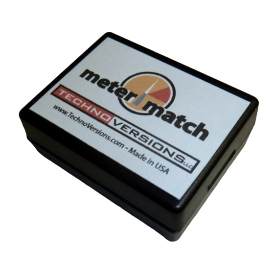
MeterMatch
™
Overview
MeterMatch™ by TechnoVersions LLC is for making analog
gauges more accurate, or to allow you to mix and match
different gauges and senders. It can be used with many
gauges that have resistive senders - such as common fuel, oil-
pressure and temperature gauges. In addition, it allows you to
have low and/or high set-points that will trigger a bright, blinking
LED indicator to alert if the gauge exceeds normal values.
Note: If you are having trouble reading the small print of this instruction manual, go to the
TechnoVersions website and open the on-line copy. You can print it out full size.
Theory of Operation
MeterMatch is wired between your sender (sensor) and your gauge. It reads the resistance of the
sender, then based on the calibration values, sends a signal to drive your gauge to the desired
reading. It treats the input and output entirely separately, so it doesn't care if the input to the gauge is
scaled differently than the sender, or even if the sender signal has a reversed sender signal than the
gauge - it can correct for that.
To calibrate MeterMatch, you first set the sender to a known value. For example, fill your fuel tank.
Set the MeterMatch to program mode, then with Up and Dn buttons, make your gauge read what you
want for that sender value. When you are happy with that, press the Save button, and the value is
remembered in the MeterMatch. Do the same process with the sender reading a value near the other
Advertisement

Related Manuals for TechnoVersions MeterMatch

Summary of Contents for TechnoVersions MeterMatch
- Page 1 - it can correct for that. To calibrate MeterMatch, you first set the sender to a known value. For example, fill your fuel tank. Set the MeterMatch to program mode, then with Up and Dn buttons, make your gauge read what you want for that sender value.
- Page 2 MeterMatch interpolates from these values to make the gauge read proportionately at values above, below, and between the calibration values. If you know the resistance of your sender, you can also calibrate to common end-values of senders, even without the sender being at that specific resistance.
-
Page 3: Installation
Installation MeterMatch is contained in a plastic enclosure that is 1.85" by 2.4" x .93". To install and calibrate it, you will need to expose the circuit by removing the small Phillips-head screw in the bottom center of the enclosure. Use a #1 or smaller Phillips screwdriver. Take care that the circuit board doesn't touch any metal which could short things out, and when finally installed, make sure it is in a dry spot that doesn't get overly hot. - Page 4 2. Set the rotary switch Ѳ to position "1" (High Calibration Point). The LED in MeterMatch will light 3. Use the Up/Dn buttons to make your gauge read the appropriate setting for the present sender output.
- Page 5 Method 1: Connect a resistor (available at places such as Radio Shack) of the desired value on the MeterMatch sender input pin (pin 3) to ground, and then perform calibration at that point just as with the standard calibration process previously shown.
- Page 6 Up/Dn buttons to make gauge read the desired setting, then Save). When the Save button is pressed (and the rotary switch Ѳ is not set to 0), MeterMatch will use the resistance value you just entered, and then reset itself to back normal operation (measuring the connected sender resistance).
- Page 7 If that's the case, simply reverse the calibration (use high for low and vice-versa). If you have more than one MeterMatch installed, you can logic "or" the LED signals so that if any of the alarm signals become true, they will set off a single LED. Simply connect the LED positive (anode) to any one of the MeterMatch circuits, and then connect all of the MeterMatch LED negative (cathode) wires to the LED negative side wire.
- Page 8 Four calibration points provided, minimum of two necessary for operation. LED Output Programmed blinking Source impedance to anode 400, open-collector to cathode Controls Up, Down, Save buttons 8-Position rotary switch (MeterMatch Instruction Manual - Rev 6/2017) - 8 -...
-
Page 9: Theory Of Operation
- it can correct for that. To calibrate MeterMatch, you first set the sender to a known value. For example, fill your fuel tank. Set the MeterMatch to program mode, then with Up and Dn buttons, make your gauge read what you want for that sender value. - Page 10 MeterMatch interpolates from these values to make the gauge read proportionately at values above, below, and between the calibration values. If you know the resistance of your sender, you can also calibrate to common end-values of senders, even without the sender being at that specific resistance.
- Page 11 Installation MeterMatch is contained in a plastic enclosure that is 1.85" by 2.4" x .93". To install and calibrate it, you will need to expose the circuit by removing the small Phillips-head screw in the bottom center of the enclosure. Use a #1 or smaller Phillips screwdriver. Take care that the circuit board doesn't touch any metal which could short things out, and when finally installed, make sure it is in a dry spot that doesn't get overly hot.
- Page 12 2. Set the rotary switch Ѳ to position "1" (High Calibration Point). The LED in MeterMatch will light 3. Use the Up/Dn buttons to make your gauge read the appropriate setting for the present sender output.
- Page 13 Method 1: Connect a resistor (available at places such as Radio Shack) of the desired value on the MeterMatch sender input pin (pin 3) to ground, and then perform calibration at that point just as with the standard calibration process previously shown.
- Page 14 Up/Dn buttons to make gauge read the desired setting, then Save). When the Save button is pressed (and the rotary switch Ѳ is not set to 0), MeterMatch will use the resistance value you just entered, and then reset itself to back normal operation (measuring the connected sender resistance).
- Page 15 If that's the case, simply reverse the calibration (use high for low and vice-versa). If you have more than one MeterMatch installed, you can logic "or" the LED signals so that if any of the alarm signals become true, they will set off a single LED. Simply connect the LED positive (anode) to any one of the MeterMatch circuits, and then connect all of the MeterMatch LED negative (cathode) wires to the LED negative side wire.
- Page 16 Four calibration points provided, minimum of two necessary for operation. LED Output Programmed blinking Source impedance to anode 400, open-collector to cathode Controls Up, Down, Save buttons 8-Position rotary switch (MeterMatch Instruction Manual - Rev 6/2017) - 8 -...
- Page 17 - it can correct for that. To calibrate MeterMatch, you first set the sender to a known value. For example, fill your fuel tank. Set the MeterMatch to program mode, then with Up and Dn buttons, make your gauge read what you want for that sender value.
- Page 18 MeterMatch interpolates from these values to make the gauge read proportionately at values above, below, and between the calibration values. If you know the resistance of your sender, you can also calibrate to common end-values of senders, even without the sender being at that specific resistance.
- Page 19 Installation MeterMatch is contained in a plastic enclosure that is 1.85" by 2.4" x .93". To install and calibrate it, you will need to expose the circuit by removing the small Phillips-head screw in the bottom center of the enclosure. Use a #1 or smaller Phillips screwdriver. Take care that the circuit board doesn't touch any metal which could short things out, and when finally installed, make sure it is in a dry spot that doesn't get overly hot.
- Page 20 2. Set the rotary switch Ѳ to position "1" (High Calibration Point). The LED in MeterMatch will light 3. Use the Up/Dn buttons to make your gauge read the appropriate setting for the present sender output.
- Page 21 Method 1: Connect a resistor (available at places such as Radio Shack) of the desired value on the MeterMatch sender input pin (pin 3) to ground, and then perform calibration at that point just as with the standard calibration process previously shown.
- Page 22 Up/Dn buttons to make gauge read the desired setting, then Save). When the Save button is pressed (and the rotary switch Ѳ is not set to 0), MeterMatch will use the resistance value you just entered, and then reset itself to back normal operation (measuring the connected sender resistance).
- Page 23 If that's the case, simply reverse the calibration (use high for low and vice-versa). If you have more than one MeterMatch installed, you can logic "or" the LED signals so that if any of the alarm signals become true, they will set off a single LED. Simply connect the LED positive (anode) to any one of the MeterMatch circuits, and then connect all of the MeterMatch LED negative (cathode) wires to the LED negative side wire.
- Page 24 Four calibration points provided, minimum of two necessary for operation. LED Output Programmed blinking Source impedance to anode 400, open-collector to cathode Controls Up, Down, Save buttons 8-Position rotary switch (MeterMatch Instruction Manual - Rev 6/2017) - 8 -...
- Page 25 - it can correct for that. To calibrate MeterMatch, you first set the sender to a known value. For example, fill your fuel tank. Set the MeterMatch to program mode, then with Up and Dn buttons, make your gauge read what you want for that sender value.
- Page 26 MeterMatch interpolates from these values to make the gauge read proportionately at values above, below, and between the calibration values. If you know the resistance of your sender, you can also calibrate to common end-values of senders, even without the sender being at that specific resistance.
- Page 27 Installation MeterMatch is contained in a plastic enclosure that is 1.85" by 2.4" x .93". To install and calibrate it, you will need to expose the circuit by removing the small Phillips-head screw in the bottom center of the enclosure. Use a #1 or smaller Phillips screwdriver. Take care that the circuit board doesn't touch any metal which could short things out, and when finally installed, make sure it is in a dry spot that doesn't get overly hot.
- Page 28 2. Set the rotary switch Ѳ to position "1" (High Calibration Point). The LED in MeterMatch will light 3. Use the Up/Dn buttons to make your gauge read the appropriate setting for the present sender output.
- Page 29 Method 1: Connect a resistor (available at places such as Radio Shack) of the desired value on the MeterMatch sender input pin (pin 3) to ground, and then perform calibration at that point just as with the standard calibration process previously shown.
- Page 30 Up/Dn buttons to make gauge read the desired setting, then Save). When the Save button is pressed (and the rotary switch Ѳ is not set to 0), MeterMatch will use the resistance value you just entered, and then reset itself to back normal operation (measuring the connected sender resistance).
- Page 31 If that's the case, simply reverse the calibration (use high for low and vice-versa). If you have more than one MeterMatch installed, you can logic "or" the LED signals so that if any of the alarm signals become true, they will set off a single LED. Simply connect the LED positive (anode) to any one of the MeterMatch circuits, and then connect all of the MeterMatch LED negative (cathode) wires to the LED negative side wire.
- Page 32 Four calibration points provided, minimum of two necessary for operation. LED Output Programmed blinking Source impedance to anode 400, open-collector to cathode Controls Up, Down, Save buttons 8-Position rotary switch (MeterMatch Instruction Manual - Rev 6/2017) - 8 -...
- Page 33 - it can correct for that. To calibrate MeterMatch, you first set the sender to a known value. For example, fill your fuel tank. Set the MeterMatch to program mode, then with Up and Dn buttons, make your gauge read what you want for that sender value.
- Page 34 MeterMatch interpolates from these values to make the gauge read proportionately at values above, below, and between the calibration values. If you know the resistance of your sender, you can also calibrate to common end-values of senders, even without the sender being at that specific resistance.
- Page 35 Installation MeterMatch is contained in a plastic enclosure that is 1.85" by 2.4" x .93". To install and calibrate it, you will need to expose the circuit by removing the small Phillips-head screw in the bottom center of the enclosure. Use a #1 or smaller Phillips screwdriver. Take care that the circuit board doesn't touch any metal which could short things out, and when finally installed, make sure it is in a dry spot that doesn't get overly hot.
- Page 36 2. Set the rotary switch Ѳ to position "1" (High Calibration Point). The LED in MeterMatch will light 3. Use the Up/Dn buttons to make your gauge read the appropriate setting for the present sender output.
- Page 37 Method 1: Connect a resistor (available at places such as Radio Shack) of the desired value on the MeterMatch sender input pin (pin 3) to ground, and then perform calibration at that point just as with the standard calibration process previously shown.
- Page 38 Up/Dn buttons to make gauge read the desired setting, then Save). When the Save button is pressed (and the rotary switch Ѳ is not set to 0), MeterMatch will use the resistance value you just entered, and then reset itself to back normal operation (measuring the connected sender resistance).
- Page 39 If that's the case, simply reverse the calibration (use high for low and vice-versa). If you have more than one MeterMatch installed, you can logic "or" the LED signals so that if any of the alarm signals become true, they will set off a single LED. Simply connect the LED positive (anode) to any one of the MeterMatch circuits, and then connect all of the MeterMatch LED negative (cathode) wires to the LED negative side wire.
- Page 40 Four calibration points provided, minimum of two necessary for operation. LED Output Programmed blinking Source impedance to anode 400, open-collector to cathode Controls Up, Down, Save buttons 8-Position rotary switch (MeterMatch Instruction Manual - Rev 6/2017) - 8 -...
Need help?
Do you have a question about the MeterMatch and is the answer not in the manual?
Questions and answers