Table of Contents
Advertisement
Quick Links
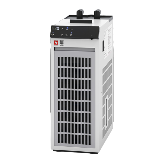
Closed Cooling Water Circulator
Neocool
model
Instruction Manual
Thank you for choosing CF302L-A
®
Neocool
Scientific Co., Ltd.
For proper equipment operation, please
read and become thoroughly familiar with
this instruction manual before use. Always
keep equipment documentation safe and
close at hand for convenient future
reference.
Warning
Yamato Scientific Co. Ltd.
®
Circulator
CF302L-A
First Edition
Circulator from Yamato
:
Read instruction manual
warnings and cautions
carefully and completely
before proceeding.
Printed on recycled paper
Advertisement
Table of Contents
Troubleshooting

Subscribe to Our Youtube Channel
Related Manuals for Yamato Neocool CF302L-A

Summary of Contents for Yamato Neocool CF302L-A
- Page 1 Always keep equipment documentation safe and close at hand for convenient future reference. Warning Read instruction manual warnings and cautions carefully and completely before proceeding. Yamato Scientific Co. Ltd. Printed on recycled paper...
-
Page 3: Table Of Contents
TABLE OF CONTENTS 1. SAFETY PRECAUTIONS ......................1 Explanation of Symbols ......................1 Symbol Glossary ........................2 Warnings and Cautions ......................3 Residual Risk Map ........................6 List of Residual Risks ........................ 7 2. COMPONENT NAMES AND FUNCTIONS ................. 10 External View .......................... - Page 4 13. OPTIONAL ACCESSORIES ..................... 36 List of Options ......................... 36 14. WIRING DIAGRAM ........................39 CF302L-A ..........................39 15. REPLACEMENT PARTS LIST ....................40 16. LIST OF HAZARDOUS SUBSTANCES ..................41 17. STANDARD INSTALLATION MANUAL ..................42...
-
Page 5: Safety Precautions
1. SAFETY PRECAUTIONS Explanation of Symbols... -
Page 6: Symbol Glossary
1. SAFETY PRECAUTIONS Symbol Glossary WARNING / CAUTION Danger! Danger! Danger! Danger! General High Voltage Extremely Hot Moving Parts Blast Hazard Caution: Caution: Caution: Caution: Caution: Do Not Heat Water Only Shock Hazard! Burn Hazard! May Leak Water! Without Water! Caution: Toxic Chemicals RESTRICTION... -
Page 7: Warnings And Cautions
1. SAFETY PRECAUTIONS Warnings and Cautions WARNING Install in a location free of flammables and explosives. Never install or operate unit in a flammable or explosive gas atmosphere. Unit is NOT fire or blast resistant. Simply switching earth leakage breaker (ELCB) "ON" or "OFF" can produce a spark, which can then be relayed during operation, causing fire or explosion when near flammable or explosive fluids, chemicals or gases/fumes. - Page 8 1. SAFETY PRECAUTIONS Warnings and Cautions Handle power cable with care. ・Do not operate unit with power cable bundled or tangled. Operating unit with the power cable bundled or otherwise tangled, may cause power cable to overheat and/or catch fire. ・Do not modify, bend, forcibly twist or pull on power cable.
- Page 9 1. SAFETY PRECAUTIONS Warnings and Cautions CAUTION DO NOT operate equipment during thunderstorms In the event of a thunderstorm, turn OFF (○) ELCB and disconnect power cable immediately. A direct lightning strike may cause equipment damage, fire or electric shock, resulting in serious injury or death.
-
Page 10: Residual Risk Map
1. SAFETY PRECAUTIONS Residual Risk Map These figures indicate positions of caution labels. The numbers shown in the figure indicate the numbers listed in the "List of Residual Risks" in this manual. For details of individual residual risks, see the List of Residual Risks. Rating label 2, 3, 6, 7, 10, 12, 14, 16... -
Page 11: List Of Residual Risks
1. SAFETY PRECAUTIONS List of Residual Risks List of residual risks (instructions for risk avoidance) This list summarizes residual risks to avoid personal injuries or damages to properties during or related to the use of equipment. Be sure to fully understand or receive instructions on how to use, maintain and inspect equipment before starting operation. - Page 12 1. SAFETY PRECAUTIONS List of Residual Risks Degree of Risk Protective measures taken by the user Relevant risks description page(s) DO NOT process explosive or flammable WARNING Explosion/Fire substances Fire/ Turn OFF (○) ELCB immediately when an WARNING Electric shock abnormality occurs.
- Page 13 1. SAFETY PRECAUTIONS List of Residual Risks Daily inspection/maintenance Degree of Risk Protective measures taken by the user Relevant risks description page(s) Fire/ Be sure to disconnect power cable before daily WARNING Electric shock inspection and maintenance. Burn/ Perform inspections and maintenance when unit WARNING Injury and circulating water is at room temperature.
-
Page 14: Component Names And Functions
2. COMPONENT NAMES AND FUNCTIONS External View Earth leakage circuit breaker Reservoir Cover (ELCB) Rating label Serial number label Condensate drain hose Control panel (included) Drain hose Intake dust filter Drain plug Drain hose Hose clamp (included) Rubber foot Drip tray (Please prepare separately) One-touch connector (L-type) Discharge... -
Page 15: Circulation System
2. COMPONENT NAMES AND FUNCTIONS Circulation System Discharge Return Rc3/8 (OUT) (IN) Rc3/8 Water reservoir Cooling coil ▼ ▼ Temperature sensor Circulation pump Drain plug Drain... -
Page 16: Control Panel
2. COMPONENT NAMES AND FUNCTIONS Control panel ① ② ⑨ ⑩ ⑥ ⑧ ④ ⑤ ③ ⑦ ⑪ Panel item Description Shows current temperature, temperature setting, Temperature display ① parameters, etc. Up key ② Increases or decreases set value, scrolls items in user setting, and switches setting items. -
Page 17: Pre-Operation Procedures
3. PRE-OPERATION PROCEDURES Installation Precautions Choose an appropriate installation site. DO NOT install unit: ・where installation surface is not completely level, not even or not clean. ・where flammable or corrosive gases/fumes may be present. ・where ambient temperature will exceed 35 °C, will fall below 5 °C or will fluctuate. ・where liquid is assumed to splash on unit ・in excessively humid or dusty locations. - Page 18 3. PRE-OPERATION PROCEDURES Installation Precautions Always connect power cable to appropriate facility outlet or terminal. Connect power cable to a suitable facility outlet or terminal, according to the electrical requirements. Electrical 115V AC 7.5 A (ELCB capacity: 10 A) requirements: Standard test conditions with no load should be as follows.
- Page 19 -20 to 5 °C: Z1 60% * Do not use pure water as circulating water ® The ready-to-use Raku-raku line of Nybrine solutions from Yamato Scientific is ® recommended. Contact original dealer of purchase for Raku-raku Nybrine solutions. Standard...
-
Page 20: Installation Procedures
4. INSTALLATION PROCEDURES Installation Procedure 1. Hose connection Connect hoses to the discharge port and return port of the cooling water circulation system. CF series units are an external closed loop circulation system. Connection can be made with 10 mm O.D. rigid hose, or with 9 mm I.D flexible hose. With optional nozzle attached, other hoses can be connected. - Page 21 4. INSTALLATION PROCEDURES Installation Procedure 2. Hose connection to the external device When a connection between unit and hose is made, connect to an external device as shown in the figure. Rotatable connector on the connection port allows free change in the direction. Adjust the direction so that the hose does not bend when connected to an external device.
- Page 22 4. INSTALLATION PROCEDURES Installation Procedure 4. Filling water reservoir Select circulating water according to "Preparation of circulating water" (P.15) 1. Open the lid and let circulating water flow into the reservoir Cooling coil until the cooling coil is immersed. 2. In this state, turn ELCB ON (|) and press the Power switch to operate and begin liquid circulation.
-
Page 23: Operation Procedures
5. OPERATION PROCEDURES Operation procedure 1. Turn on power 1. Turn ELCB ON (|). 2. Turn the Power switch ON (|). Temperature : Shows temperature reading display following the software version "V. ○.○" Ref lamp : Flashing (goes off after about three minutes) indicates flashing. -
Page 24: User Setting
5. OPERATION PROCEDURES User Setting List of user setting items Press and hold key for three seconds. User setting items will be shown. Select an item using the ∧∨ keys. Press key again to edit the displayed item. While the user setting item is displayed, leaving unit without key operation for about two minutes ... -
Page 25: Calibration Offset
5. OPERATION PROCEDURES Calibration offset Calibration offset is a function which can correct for any differences discovered between actual liquid temperature and the temperature displayed on the control panel. Offset function can correct to either the positive or negative side of the entire unit temperature range. ・Run unit at desired temperature. -
Page 26: Auto-Resume Function
5. OPERATION PROCEDURES Auto-resume function Select recovery mode for the event of a power failure. OFF: Unit goes into idle at power recovery. (Default setting) ON: Unit automatically reverts to status just before power loss and begin operation once again from that point. -
Page 27: Selection Of Circulation Pump Operation At Temperature Upper Limit Alert
5. OPERATION PROCEDURES Selection of circulation pump operation at temperature upper limit alert Select the circulation pump operation for the time temperature upper limit alert (Hi) is raised and temperature reading exceeds 40 °C. OFF: Circulation pump will remain in idle. ON: Circulation pump begins running with the pump key ON. -
Page 28: Led Brightness Setting
5. OPERATION PROCEDURES LED brightness setting Change the LED brightness of the control panel. The brightness can be set in 8 levels from 0 to 7. (Default setting: "3"). Enter user setting Turn power switch ON (|) and press key for three seconds while temperature reading is on the screen. -
Page 29: Handling Precautions
6. HANDLING PRECAUTIONS Warnings and Cautions CAUTION NEVER process explosive or flammable substances Never attempt to process explosives, flammables or any items which contain explosives or flammables. Fire or explosion causing serious injury or death may result. See "16. LIST OF HAZARDOUS SUBSTANCES"... - Page 30 6. HANDLING PRECAUTIONS Warnings and Cautions Circulation pump. ・Never operate circulation pump dry. Damage or malfunction may result. Operating unit without circulating water in the reservoir and circulation pump may cause seizure of the pump and/or other problems. ・Keep water reservoir covered and do not allow any debris to enter and remain in the reservoir.
-
Page 31: Maintenance Procedures
7. MAINTENANCE PROCEDURES Inspection and Maintenance WARNING Be sure to disconnect power cable before conducting inspection and maintenance, unless otherwise necessary. Inspect and perform maintenance when unit and circulation water is at room temperature. Never attempt to disassemble unit. CAUTION ... -
Page 32: Inspection And Maintenance
7. MAINTENANCE PROCEDURES Inspection and Maintenance Water reservoir maintenance Remove any foreign substances and debris from water reservoir as frequently as possible. Failure to do so may cause damage to circulation pump. Wear proper gloves when performing reservoir maintenance. Cleaning intake dust filter. A clogged intake dust filter will degrade cooling performance and may result in refrigeration system malfunction. -
Page 33: Extended Storage And Disposal
Dispose of this unit in accordance with local laws and regulations. Dispose of or recycle this unit in a responsible and environmentally friendly manner. ・ Yamato Scientific Co., Ltd. strongly recommends disassembling unit, as far as is possible, in order to separate parts and recycle them in contribution to preserving the global environment. Major... -
Page 34: Troubleshooting
9. TROUBLESHOOTING Error Codes Unit has a self-diagnostic function built into the CPU board and a separate safety device, independent of the CPU board. The table below shows possible causes and measures to take when safety device is triggered. [Error Codes] If an abnormality occurs, the following error code and measured temperature are displayed alternately on the screen, and operation stops. -
Page 35: Troubleshooting Guide
9. TROUBLESHOOTING Troubleshooting Guide Symptom Possible causes Possible measures ● Power supply failure ● Check power supply voltage Display is blank when ELCB and (must be 115 V AC ±10%) the Power switch ● ELCB failure ● Replace relevant parts are turned ON (|). -
Page 36: Service & Repair
Warranty period is 1 (one) year from date of purchase. ● Consult with original dealer of purchase or Yamato sales office for any repair after warranty ended. Charged repair service of this equipment will be available on customer's request when it can be maintained functional by its repair. -
Page 37: Specifications
11. SPECIFICATIONS ® Product Name Neocool circulator Model CF302L-A System/circulating water Closed circulation/tap water, antifreeze solution (below 10 °C) Operating ambient temperature range 5 to 35 °C Temperature setting range *1 -20 to 30 °C ±1.0 °C (≧0 °C) Temperature control accuracy (JTM K05) *2 ±1.5 °C (<0 °C) 3.0 °C(≧0 °C) -
Page 38: Reference Data
12. REFERENCE DATA Cooling Capacity Curve The following graphs show cooling capacities and characteristics. Findings may vary with sample quantity, ambient temperature, individual differences and other factors. Use graph values as reference only. Analysis provisions ・Room temperature measurement: at the center of condenser inlet ・Circulating water: 60% dilution of Nybrine ・Power supply: 115 V AC ®... -
Page 39: Pump Performance Curve
12. REFERENCE DATA Pump Performance Curve The following graph shows the pump performance curve. Findings may vary with sample quantity, ambient temperature, individual differences and other factors. Use graph values as reference only. Analysis provisions ・Room temperature: 23 °C ・Circulating water: 20 °C tap water, 60% dilution of Nybrine ®... -
Page 40: Optional Accessories
13. OPTIONAL ACCESSORIES List of Options A variety of optional accessories are available to suit the piping system of external device and for a wide range of uses. Contact original dealer of purchase for requests for options. Circulation connection components (fittings) Product Name Product Description... - Page 41 13. OPTIONAL ACCESSORIES List of Options Circulation connection components (hoses) Product Name Product Description Contents code Thermal insulation 221581 Usable temperature range: Standard: φ9 mm × φ13 mm × 2 m 2 pc hose -20 to 80 °C (insulation: 28 mm O.D.) * No freezing of circulating water Hose clamp 4 pc...
- Page 42 13. OPTIONAL ACCESSORIES List of Options External interlock input terminal Product Name Product code Description 281484 Unit will be shipped with the terminal block (2P) attached to the rear of unit. External interlock input terminal This function is to start and stop cooling operation + circulation operation, or only circulation operation of unit by external control input (no-voltage a INPUT contact input).
-
Page 43: Wiring Diagram
14. WIRING DIAGRAM CF302L-A... -
Page 44: Replacement Parts List
15. REPLACEMENT PARTS LIST Part name Part code Standard Manufacturer Yamato One-touch LT00039314 R3/8 Scientific connector (L-type) Hose nozzle Yamato LT00039316 10 mm O.D. connectors for Scientific flexible hose with 9 mm I.D. Yamato Intake dust filter CF30243000 Front air intake... -
Page 45: List Of Hazardous Substances
16. LIST OF HAZARDOUS SUBSTANCES Never attempt to process explosives, flammables or any items which contain explosives or flammables. ①Nitroglycol, Glycerine trinitrate, Cellulose Nitrate and other explosive nitrate esters ②Trinitrobenzen, Trinitrotoluene, Picric Acid and other explosive nitro compounds ③Acetyl Hydroperoxide, Methyl Ethyl Ketone Peroxide, Benzoyl Peroxide and other organic peroxides ④Metallic Azide, including Sodium Azide, etc. -
Page 46: Standard Installation Manual
17. STANDARD INSTALLATION MANUAL * Install this equipment according to following format (check options and special specifications separately). Charged Personnel Installation Installation Model Serial Number or Company Name Judgment Date proved by for Installation № Item Implementation method Chapter № & Reference page of Judgment instruction manual Specifications... - Page 47 Notice ● Instruction manual descriptions and specifications are subject to change without notice. ● Yamato Scientific Co., Ltd. will replace flawed instruction manuals (pages missing, pages out of order, etc.) upon request. Instruction Manual ®...
Need help?
Do you have a question about the Neocool CF302L-A and is the answer not in the manual?
Questions and answers