Advertisement
Quick Links
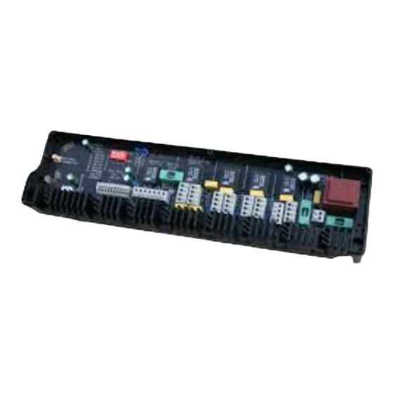
SE1
SMART ENERGY SWITCH
The SE1 Smart Energy Switch is a wiring
control centre for most central heating/
cooling system on the market today.
The device is capable of controlling
heating/cooling appliances as well as the
zoned distribution of the heating/cooling
water.
Connections for up to 9 pumps/zone
valves with 5 control points that can
be connected to any of the 4 zones.
Applications include S, Y, W plan heating
systems, zone pump control heating
systems, underfloor heating and many
other applications including cooling.
It is possible to have more than 1 SE1
device in the same network for virtually
limitless control combinations. Designed
for easy/rapid installation with built-in
manual override switches for fast testing
and commissioning. Enables the installer
to create complex control systems
with ease and without the need for an
engineer.
App control as standard.
Works as a part of the MUONIO
smart control system for heating and
ventilation.
USER MANUAL
Advertisement

Summary of Contents for Muonio SE1
- Page 1 Applications include S, Y, W plan heating systems, zone pump control heating systems, underfloor heating and many other applications including cooling. It is possible to have more than 1 SE1 device in the same network for virtually limitless control combinations. Designed for easy/rapid installation with built-in manual override switches for fast testing and commissioning.
- Page 2 Wiring external to the printed circuit board MUST be in accordance with current statutory wiring regulations and any local regulations that apply. The power supply must be 230 V~, 50/60 Hz, Single Phase. Attaching the SE1 board to more than one phase will cause irreparable damage.
- Page 3 Relay 2-5 each have 3 parallel power outputs Ground/Earth Terminal Points Easy ‘Push-Open’ Connections WIRELESS FREQUENCY 2.4 GHz with external antenna option ENCLOSURE RATING IP20 TRANSIENT SUPPRESSION DEFROST SUPPORT CONTENT IN THE BOX SE1 device, DHW sensor, manual, external antenna HARDWARE VERSION...
- Page 4 Terminal Identification & Description MANUAL RELAY S WITCH: RELAY 2 POWER OK 1) RELAY 1 RESERVED FOR 2) RELAY 2 DOMESTIC RELAY 1 BOILE R HOT WATER 3) RELAY 3 RELAY 4 RELAY 5 RELAY 3 4) RELAY 4 BOILER FUSE 12 34 56 5) RELAY 5...
-
Page 5: Auxiliary Inputs
Relay 1 will trigger and fire the boiler, this happens regardless of any software settings. The auxiliary terminals can be used to daisy chain multiple SE1 relay boards, for frost protection, for triggering the boiler after a valve relay is closed (S-plan wiring) and more. - Page 6 If for some reason the system does not detect the attached sensor it will continue to operate as per the schedule without temperature control until the issue is rectified. Each SE1 device in the system can have one control point for DHW. Relay 2 is reserved for DHW control and cannot be used for other purposes.
- Page 7 ID KEY into the SE1 relay board (Figure 9) while it is powered off. Once this is done power on the SE1 device while the ID KEY is still inserted into it. If all the steps have been done correctly and the SE1 is within FIGURE 9.
- Page 8 Adjacent relay 1, there are terminals for the boiler power supply fused at 3 A ensuring all boiler wiring requirements can be supplied from the SE1 device. Relay 1 can be triggered by the auxiliary inputs as explained erlier.
- Page 9 Figure 11 above. This is done by connection the boiler switch (terminals 9 & 10) from one board to the Auxiliary input (terminals 7 & 8) on a different board. When SE1 - DEVICE 1 is calling for heat it will trigger the auxiliary input on SE1 - DEVICE 2, which will trigger the boiler connected to SE1 - DEVICE 2 terminals 9 &...
- Page 10 (or cooling) it will trigger relay 3. Connect the auxiliary end switches in the zone valve to any pair of volt free inputs (6a,7a) (6b,7b) (6c,7c) or (6d,7d) on the SE1 device. Relay 1 will be triggered when the volt-free input contacts on the SE1 are closed by the motorized valve auxiliary end switch, thus firing the boiler.
- Page 11 Software HOME PAGE The top right-hand side of the home page shows the ALARM button and the MENU button on the top left. By pressing the MENU button you get a list of options to choose from. By pressing the ALARM button you can check the current alarm status for the various devices connected.
- Page 12 Software explained ZONE SETINGS MENU EXPLAINED Current zone parameters. Depending on the type of sensor in the zone, it can read temperature/humidity and additionally air quality data if required. Heating settings OFF - The Zone is fully off but it will turn on if the ambient temperature drops OFF F below 4°C for frost protection.
- Page 13 Software explained HEATING/COOLING SETTINGS* Schedule ON/OFF - if you turn on schedule, the current mode of work will be set as per the schedule. If a schedule is not selected you will be able to manually select any of the 4 modes of work (Home, Away, Sleep, Off)and no further settings are considered.
- Page 14 Software explained HEATING/COOLING SCHEDULE Each day can have a separate schedule. There are default values inside that you can alter. Each day is divided into a maximum of 24 periods with a minimum duration of 1-hour. Each period can have one of the 4 modes of work (OFF, HOME, AWAY, SLEEP) selected.
-
Page 15: Software Settings
RELAY 4 RELAY 5 HOT WATER COOLING relay is used for heating and cooling. In that case the heat pump and the Muonio software have to be switched between heating and cooling twice a year.(Typically RELAY 1 RELAY 2 RELAY3... -
Page 16: Domestic Hot Water Settings
NO. FIG 12. shows how valves with auxiliary switches are connected. CONNECTION OF THE SENSOR Connect the DHW sensor to connections 1, 2 and 3 on the SE1 board by plugging it into the correct position. Place the sensor head in a designated pocket that can... - Page 17 Domestic Hot Water Settings RELAY 2 EXPLANATION T- L Aux- L T-SL EXPLANATION: N - Neutral AUX_L - aux call for the boiler (Relay 1). If you supply this terminal with a 230Vac Switch Live, it will trigger Relay 1 (boiler relay). This terminal has the same function as 6a,b,c,d and 7a,b,c,d except 6/7 terminals are volt free inputs.
- Page 18 In this scenario, we are using the hot water sensor supplied DHW TANK * SENSOR with the SE1 device (FIGURE 8.) immersed in the tank. When the setpoint is higher than the actual temperature in the tank, the system will call for DHW (depending on the schedule or mode selected).
- Page 19 1 CALL is set to NO because we don’t want Relay 2 to fire the boiler when there is a need for DHW, instead we want the boiler to fire when Valve 1 is fully open. RELAY 1 CALL If your system doesn’t have a DHW sensor installed the SE1 can still control the FIGURE 20. S PLAN SOFTWARE DHW, but without temperature control.
- Page 20 Wiring examples - Y plan heating Y PLAN HEATING Typical 3 port valve wiring RADIATOR RADIATOR Blue (Neutral) 3 PORT Green/Yellow (Earth) White (Heating on) * SENSOR Orange (Boiler and pump live) BOILER FIGURE 22. Y PLAN HEATING EXAMPLE MANUAL RELAY S WITCH: RELAY 2 POWER OK 1) RELAY 1...
- Page 21 FIGURE 25. OPTIONAL WIRING FOR Y Do not wire an immersion heater to the SE1. The relay board is not designed for such high outputs. If you need to control an immersion heater for DHW you have to use an additional relay.
- Page 22 Wiring examples - Heating/Cooling with pumps HEATING/COOLING WITH ZONE Systems with multiple circulation pumps, if executed correctly, deliver good water flow to all the branches of the system. They are easy to balance, and they don’t require the boiler to wait for a valve to open before firing. Boiler SYSTEM MANIFOLD Sensor...
- Page 23 FIGURE 29. OPTIONAL WIRING FOR If your system doesn’t have a DHW sensor installed the SE1 can still control the DHW, but without temperature control. From the app you will be able to turn DHW generation ON/OFF, or you can set up an hourly schedule for DHW generation.
- Page 24 Wiring examples - W plan heating W PLAN HEATING This scheme uses a 3 port diverter valve, which has only 2 settings - heating only or hot water only. The valve is in position A by default, which is for hot water. The valve moves to position B (Heating) when power is applied. RADIATOR RADIATOR DIVERTER VALVE...
- Page 25 SOFTWARE SETTINGS For the W-Plan system in this example only Relay 1 is SE1 DEVICE SETT INGS selected for the heating zone. This is because the valve is in the heating position whenever there is no call for hot water SETUP BOARD so Relay 3-5 are not needed.
-
Page 26: Software Setup
Software setup RELAY MAC ADDRESS _____________________________ NAME _______________________ ZONE 1 MAC ADDRESS _____________________________ NAME _______________________ RELAY RELAY 2 - HOT WATER RELAY RELAY RELAY ZONE 2 MAC ADDRESS _____________________________ NAME _______________________ RELAY RELAY 2 - HOT WATER RELAY RELAY RELAY ZONE 3 MAC ADDRESS _____________________________... - Page 27 Schematics & Notes MANUAL RELAY S WITCH: RELAY 2 POWER OK 1) RELAY 1 RESERVED FOR 2) RELAY 2 DOMESTIC RELAY 1 BOILE R HOT WATER 3) RELAY 3 RELAY 4 RELAY 3 RELAY 5 BOILER FUSE 4) RELAY 4 12 34 56 5) RELAY 5 F3:3A...
- Page 28 Schematics & Notes DATE________________JOB___________________ CUSTOMER SIGNATURE_______________________...
- Page 29 Contacts YOUR INSTALLER DISTRIBUTOR: WWW.MUONIO.ME...
-
Page 30: Warranty
CUSTOMER FOR INSTALLATION OR REMOVAL OF WARRANTED ITEMS. YEAR AFTER THE CAUSE OF THE ACTION HAS OCCURRED. THIS WARRANTY DOES NOT COVER PARTS OR EQUIPMENT USED WITH MUONIO MISCELLANEOUS UNITS THAT MOUNIO DOES NOT MANUFACTURE OR SUPPLY AS PART OF THEIR EXCEPT AS PROVIDED HEREIN, NO EMPLOYEE, AGENT, DEALER OR OTHER PERSON IS PRODUCT.
Need help?
Do you have a question about the SE1 and is the answer not in the manual?
Questions and answers