Advertisement
Quick Links
Advertisement

Related Manuals for XVIVO Liver Assist

Summary of Contents for XVIVO Liver Assist
- Page 1 11.01.601.07a EN...
- Page 2 Model Numbers: 11.01.201, 11.01.202, 11.01.203, 11.01.204 Patented 2797 XVIVO B.V. Bornholmstraat 84 9723 AZ Groningen THE NETHERLANDS +3150 3131905 info.xnl@xvivogroup.com www.xvivogroup.com 24/7 Helpdesk (for urgent calls only) +31 50 3640116 MedEnvoy Switzerland Gotthardstrasse 28 6302 Zug Switzerland 11.01.601.7c EN Page...
- Page 3 Product description 1.1 Intended use 1.2 Pump unit 1.3 Thermo unit 1.4 Trolley 1.5 Disposable set 1.6 Ordering information 1.7 Product specifications Installation Operation 3.1 Preparing the perfusion procedure 3.2 Perfusion procedure 3.3 In-hospital transport 3.4 Stopping the operation Cleaning 4.1 After every procedure 4.2 Weekly: disinfection thermo unit 4.3 Yearly: decalcifying thermo unit...
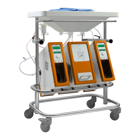
- Page 4 Temperature sensors (3x) • Flow sensors (2x) • Instructions for Use • Thermo water tubing • Water tubing couplers (2x) Figure 1: Liver Assist with pump units, thermo unit, and disposable holder connected to the trolley 11.01.601.7c EN Page 4 of 40...
- Page 5 6 hours. The Liver Assist is intended for use by trained professionals in a professional healthcare environment. Users are expected to be familiar with standard medical practices as required for organ perfusion.
- Page 6 Figure 3: Right and left-hand side view of the pump units Control panel Reservoir temperature Oxygen cylinder connection (T Oxygen cylinder compartment Perfusion temperature Electrical power inlet connection (T Data cable connection Pressure sensor cable USB connection connection Equipotentiality pin Flow sensor connection Product label Magnetic pump coupling...
- Page 7 Control Panel Control display, showing menu and relevant data Display showing Display showing perfusion actual flow temperature OK button Down button Up button Attention temperature Attention indicator indicator Power Pump on/off indicator indicator Pump on/off Power button button Pause audible alarm button Figure 4: Control panel.
- Page 8 Figure 5: Front and rear view of the thermo unit Figure 6: Right and left-hand side view of the thermo unit 11.01.601.7c EN Page 8 of 40...
- Page 9 Figure 7: Accessories thermo unit; quick-connect thermo water connectors, flow indicator, thermo water coupling tube and tubing Thermo reservoir Thermo water outlet Electrical power inlet connector Data cable connection Air intake vents Electrical power outlet Air outlet vents Equipotentiality pin Water connector Product label Water tubing coupler...
- Page 10 Figure 8: Trolley Table Screw holes for connection of Organ reservoir holder pump and thermo units Push Bar Product label Oxygenator holder Pressure sensor holder 11.01.601.7c EN Page 10 of 40...
- Page 11 Figure 9. Disposable set Sterile lid with drape Flow sensor tube PV Inner lid Perfusion lines PV Sterile reservoir Bile line Filling line PV Filling line HA Pressure sensor PV Pressure sensor HA Temperature sensor T2 Sample line HA connection Oxygen line HA Sample line PV Oxygenator HA...
- Page 12 The following Liver Assist parts, accessories and single use disposables can be (re)ordered: Item Order number Liver Assist 11.01.101 Pump unit (PV) 11.01.201 Pump unit (HA) 11.01.202 Thermo unit 11.01.203 Trolley 11.01.204 Work table 11.01.212 Disposable NL40046511 11.451 Temperature sensor blue 05.01.301...
- Page 13 Perfusion pump: Rotary pump, pulsatile 60 BPM (HA) + continuous (PV) Perfusion flow: HA: up to 570 ml/min @ 12 °C / up to 1 L/min @ 37 °C PV: up to 500 ml/min @ 12 °C / up to 2 L/min @ 37 °C Perfusion pressure: HA: up to 50 mmHg @12°C / up to 90 mmHg @ 37 °C PV: up to 11 mmHg @12 °C / up to 16 mmHg @ 37 °C...
- Page 14 The complete Liver Assist is shipped in separate cardboard packages. The device has to be unpacked, checked and installed by an XVIVO authorized person. • Set the trolley in the correct position (figure 8). • Position the pump and thermo units on the trolley, the HA pump unit on the left side, the PV pump unit on the right side (figure 1).
- Page 15 Before starting the procedure, check the units, trolley, sensors, cables and connections. Do not use a damaged device. • Power on the Liver Assist by pushing the power button on the control panel. • Wait until the self test is completed.
- Page 16 Connect the pump head to the magnetic pump coupling located on the outer sides of the Liver Assist pump units (figure 3, item 14). Push the pump head in the coupling and turn the pump head to lock it, see figure 11, ensure it is placed correctly. The outlet of the pump heads shall be orientated horizontal to easily de-air the pump heads.
- Page 17 Every sensor is different and is not interchangeable. Connect the sensors to the right sub connectors, else it could cause damage. Do not spill any fluid on the electronic connectors; this may cause a deviation of the measured values or to an alarm. Do not load more than 15 Kg on the table top, including organ and liquids.
- Page 18 push turn Figure 14: Connection of the temperature sensor to the disposable system • To fill the circuit; connect the 2 separately packed filling lines to the PV and HA oxygenators, see figure 15. Take care to connect it tightly and maintain sterility. •...
-
Page 19: Priming System
If you are uncertain about which solutions are appropriate, contact XVIVO for information on recommended perfusates that work best with the Liver Assist. Using other solutions than machine perfusion solution with the Liver Assist may result in organ damage or the cause of complications. PORTAL VEIN... - Page 20 HEPATIC ARTERY PORTAL VEIN Pressure zeroing Pressure zeroing Turn transducer Turn transducer valve valve Press to continue Press to continue • Remove cap on top of the pressure sensor (transducer) and place a sterile syringe on the opened port (figure 15). •...
- Page 21 Before continuing to the next step, please ensure that the pressure sensor valve is in the correct position (figure 14). HEPATIC ARTERY PORTAL VEIN Set Temp Setpoint Press -/+ to adjust Value: .. °C Press to continue • Set the preferred temperature of the perfusion solution by using the up- and down buttons.
- Page 22 • Turn on the oxygen supply and adjust oxygen flow such that required saturation is reached (please check the user manual of the oxygenator for maximal flow). • Cannulate aortic stump (24 Fr, straight) and portal vein (24 Fr, bend). •...
- Page 23 XVIVO. If perfusion is unrecoverable, continue preservation using static cold storage. In case of an emergency, stop the Liver Assist by pressing the pump buttons to stop the operation, the device will stop the pumps.
- Page 24 Powering off the Liver Assist will reset all values back to the manufacturer’s settings. Note; The system is equipped with temperature dependent limits on flow and pressure to prevent damage or organ loss. These values are a preset safety value and cannot be changed.
- Page 25 The Liver Assist can be battery operated for a limited time (20 minutes) to allow transportation within the hospital from room to room during the perfusion procedure. During transport perfusion will continue but temperature control shall not be available. When the mains is disconnected for transport, an alarm will warn the user every minute as a reminder that the device is running on batteries.
- Page 26 • Clean the exterior of the device with a non-aggressive cleaning fluid or detergent to remove all inequities. • Allow to air dry and inspect for damage or deterioration of the surfaces. • Do not use any abrasives as this will damage the surface of the device. •...
- Page 27 14. Power off the PV pump unit and drain the thermo unit and water tubing (see step 15. Second Rinse: Add 2 liter of demineralized water to the thermo unit, circulate the water for 5 minutes at room temperature; check if the red flow indicator wheel is spinning to ensure flow.
- Page 28 Use of the device in procedures other than those described in this manual may result in injury. • Safe use of the Liver Assist can only be guaranteed when the operator is a skilled and trained professional and has successfully followed a Liver Assist training course.
- Page 29 • The Liver Assist is not intended to be in contact with the patient and therefore falls outside the definition of applied part. The disposable set is in contact with the subsequent isolated organ.
- Page 30 Message Priority Audible Signal Visible Signal (LED) Warning Low priority (LP) Yellow: general alarms User awareness is required, — __ Cyan: temperature related alarms optimal perfusion compromised. Error Medium priority (MP) C C C Yellow: general alarms Prompt user response is required, —...
- Page 31 Prio Alarm Problem Probable Cause Solution Self-test FAILED Internal hardware Failure of device Service message on display problem during startup (MP) Medium priority alarm No pressure sensor Pressure sensor not Connect pressure sensor with no display connected to pump unit message during startup (LP) Sensor disconnected...
- Page 32 No Power at outlet Make sure outlet has power Fuse blown Call XVIVO service Beeping or flashing Errors detected by the Liver Assist Follow the instructions in 6.1, Fault Message Explanation. LEDs Pump not working Defect pressure sensor Replace pressure sensor...
- Page 33 (WEEE). Do not dispose the device yourself. If users in the European Union wish to discard the device at the end of its useful life, contact XVIVO to arrange a retrieval of your Liver Assist. XVIVO shall ensure that your discarded product undergoes the necessary treatment, recovery and recycling procedures free of charge.
- Page 34 Table 2. Guidance and manufacturer’s declaration – electromagnetic immunity The Liver Assist is intended for use in the electromagnetic environment specified below. The customer or the user of this device should assure that it is used in such an environment.
- Page 35 If the user voltage variations 0°, 45°, 90°, 135°, 0°, 45°, 90°, 135°, of the Liver Assist requires continued operation on power supply 180°, 225°, 270° and 180°, 225°, 270° and during power mains interruptions, it is input lines 315°...
- Page 36 Table 3. Guidance and manufacturer’s declaration – RF wireless communication equipment Immunity The Liver Assist is intended for use in the electromagnetic environment specified below. The customer or the user of this device should assure that it is used in such an environment.
- Page 37 Warning LOT number SERIAL number Sterile, method using Ethylene Oxide Reference model number Do not reuse or resterilize, single use only Do not use if package is damaged Date of manufacture Manufacturer Storage condition, temperature Indicates the range of humidity to which the medical device can be safely exposed 106kPa Indicates the range of atmospheric pressure to which the medical...
- Page 38 Equipotentiality terminal for the connection of a Potential Equalization Conductor Replaceable fuse, specific type, current and voltage ratings noted above this symbol USB-port, should only be used for servicing activities by XVIVO- certified personnel Importeur / importateur / importatore Amperes...
- Page 39 …………………………………………………………………………………… …………………………………………………………………………………… …………………………………………………………………………………… …………………………………………………………………………………… …………………………………………………………………………………… …………………………………………………………………………………… …………………………………………………………………………………… …………………………………………………………………………………… …………………………………………………………………………………… …………………………………………………………………………………… …………………………………………………………………………………… …………………………………………………………………………………… …………………………………………………………………………………… …………………………………………………………………………………… …………………………………………………………………………………… …………………………………………………………………………………… …………………………………………………………………………………… …………………………………………………………………………………… 11.01.601.7c EN Page 39 of 40...
- Page 40 11.01.601.7c EN Page 40 of 40...