Table of Contents
Advertisement
Quick Links
Advertisement
Table of Contents

Summary of Contents for GME AISR120
- Page 1 AISR120 AIS RECEIVER INSTRUCTION MANUAL AISS120 Instruction Manual...
-
Page 2: Table Of Contents
ABOUT YOUR AIS RECEIVER About AIS ....................5 What’s in the Box? ..................6 INSTALLATION ..................8 Preparing for Installation ................8 Installation Procedures ................9 OPERATION ..................16 Using the AIS Receiver ................16 Indicator Functions ..................16 TROUBLESHOOTING ................17 SPECIFICATIONS ..................18 GME WARRANTY AGAINST DEFECTS ............19 AISS120 Instruction Manual... -
Page 3: Notices
NOTICES When reading this manual please pay particular attention to warnings marked with the warning triangle shown on the left. These are important messages for safety, ! installation and usage of the product. SAFETY WARNINGS • This equipment must be installed in accordance with the instructions provided in this manual. - Page 4 Warranty The product is supplied with standard warranty as defined in the Warranty statement supplied with the product. Any attempt to tamper with or damage the product will invalidate the warranty. Disposal of this Product and Packaging Please dispose of this AIS antenna splitter in accordance with the European WEEE Directive or with the applicable local regulations for disposal of electrical equipment.
-
Page 5: About Your Ais Receiver
ABOUT YOUR AIS RECEIVER ABOUT AIS The marine Automatic Identification System (AIS) is a location and vessel information reporting system. It allows vessels equipped with AIS to automatically and dynamically share and regularly update their position, speed, course and other information such as vessel identity with similarly equipped vessels. -
Page 6: What's In The Box
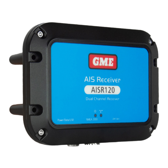
WHAT’S IN THE BOX? Figure 1 shows the items included with your AIS antenna splitter purchase. The following sections give a brief overview of each item. Please ensure all items are present and if any of the items are not present contact your dealer. Dual channel AIS receiver Power and data cable Screws... - Page 7 Indicator lights GreenA mber Mounting Mounting holes holes Power and data VHF antenna NMEA 2000 Figure 2 AIS receiver overview Electrical Connections The AIS receiver has the following electrical connections: • Power supply • NMEA0183 data port for connection to chart plotters •...
-
Page 8: Installation
INSTALLATION PREPARING FOR INSTALLATION Figure 4 shows a typical installation configuration for the AIS receiver. Please take the time to familiarise yourself with the system elements and their connections prior to attempting installation. Chartplotter VHF antenna Dual channel AIS receiver Power in NMEA0183 device... -
Page 9: Installation Procedures
Antenna Cables Please check that the VHF antenna you intend to use has sufficient cable to reach between the VHF antenna and the AIS receiver unit. If it is not sufficient you will need an extension cable. Please contact your dealer for details of suitable products. For reference the VHF antenna connector type on the AIS receiver unit is SO239, and is intended to mate with a PL259 connector. - Page 10 Step 1 - Installing the AIS Receiver Please note the following guidelines when selecting a location for your AIS receiver: • The AIS receiver must be fitted in a location where it is at least 0.5m from a compass. • There should be adequate space around the AIS receiver for routing of cables. See Figure 5 for details of the AIS receiver dimensions.
- Page 11 Figure 6 AIS receiver mounting Step 2 - Connecting the VHF Antenna Route the cable from the VHF antenna to the AIS antenna splitter and connect to the VHF antenna connector on the AIS antenna splitter as shown in Figure 7. A standard marine band VHF antenna or AIS antenna should be used with the AIS antenna splitter.
- Page 12 Step 3 - Connecting the Accessory Cable An accessory cable is supplied with the product to provide connections to power, the NMEA0183 data ports and USB. The cable has a premoulded connector at one end which should be connected to the connector on the unit marked ‘PWR/DATA’. The other end of the cable has eight colour coded bare wires ready for connection and a USB connector for use with a PC.
- Page 13 Step 4 - Connecting to NMEA0183 Compatible Equipment The two independent NMEA0183 data ports provide connection to your chart plotter and other NMEA0183 compatible equipment. Each port consists of two wires colour coded as shown in the table in Figure 8 and in the diagram in Figure 9. Connect the wires to the appropriate connections on your NMEA0183 compatible equipment.
- Page 14 Mac. To install the drivers please follows the steps below: 1. Download the installation software from the GME website located on the product page. 2. Double click on the setup.exe file to launch the installer.
- Page 15 Step 9 - Connecting to a Power Supply The AIS receiver requires either a 12V or 24V power supply typically provided by the vessel’s battery, or it can be powered via USB. It is recommended that crimped and soldered lugs are used to connect the AIS receiver to the power source.
-
Page 16: Operation
OPERATION USING THE AIS RECEIVER Once the unit has been installed it is ready for use. Providing other vessels with AIS transceivers installed are within radio range of your vessel you should see their details appear on your chart plotter or PC. Specific details of how to configure your chart plotter to make use of the AIS receiver features will be given in your chart plotter manual. -
Page 17: Troubleshooting
TROUBLESHOOTING Issue Possible Cause and Remedy No data is being received by the chart Check that the power supply is connected plotter correctly. Check that the connections to the chart plotter are correct. Check that the VHF antenna is correctly connected in accordance with the instructions in the manual The power indicator is not illuminated... -
Page 18: Specifications
SPECIFICATIONS Parameter Value Dimensions 140 x 100 x 42 mm (L x W x H) Weight 250g (AIS receiver unit only) Power DC (9.6 - 31.2V) or USB powered Average power consumption <1W Current consumption <200mA at 12VDC Electrical interfaces NMEA0183 38.4kBaud output NMEA0183 4.8kBaud input NMEA2000 LEN=1... -
Page 19: Gme Warranty Against Defects
GME WARRANTY AGAINST DEFECTS This warranty against defects is given by GME Pty Ltd ACN 000 346 814 (We, us, our or GME). Our contact details are set out in clause 2.7. Consumer guarantees 1.1 Our goods come with guarantees that cannot be excluded under the Australian Consumer Law. - Page 20 (f)) goods where the serial number has been removed or made illegal. Warranty period 4.1 We provide the following warranty on GME and Kingray products. No repair or replacement during the warranty period will renew or extend the warranty period past the period from original date of purchase.
- Page 21 GME Pty Ltd 17 Gibbon Road, Winston Hills NSW 2153, Australia Part Number: 310549 Drawing Number: 45908-3...
Need help?
Do you have a question about the AISR120 and is the answer not in the manual?
Questions and answers