Table of Contents
Advertisement
Advertisement
Table of Contents

Summary of Contents for Rishabh RISH LM 1340
- Page 1 Operating Manual RISH LM 1340...
-
Page 3: Table Of Contents
DIGITAL MULTIFUNCTION INSTRUMENT Installation & Operating Instructions Section Contents Introduction Measurement and Energy/Counter Screens 2.1 Current Reversal Screen Phase Rotation Error Screen 2.3 Phase Absent Screen 2.4 Individual Harmonics 2.5 Load Health Monitor Screen 2.5.1 Load Health Monitor Fault Screens 2.6 Pre-Paid Energy Menu 2.7 Timer 1 &... - Page 4 3.2.2 Communication Parameter Selection 3.2.2.1 Address Setting 3.2.2.2 RS 485 Baud Rate 3.2.2.3 RS 485 Parity 3.2.2.4 Quit Communication Parameters 3.2.3 IP Parameter Selection 3.2.3.1 IP Address Setting 3.2.3.2 Subnet mask Setting 3.2.3.3 Default gateway Setting 3.2.3.4 Server Port Setting 3.2.3.5 Quit IP Parameters 3.2.4 Reset Parameter Selection 3.2.4.1 Resetting Parameter...
- Page 5 3.2.5.1.1.3.5 Quit Timer Output 3.2.5.1.1.4 Health Monitor Output 3.2.5.1.1.4.1 Health Monitor Configuration 3.2.5.1.1.5 Pre Paid Energy Output 3.2.5.1.1.5.1 Parameter Selection 3.2.5.1.1.5.2 Unit Cost 3.2.5.1.1.5.3 Topup Recharge 3.2.5.1.1.5.4 New Recharge 3.2.5.1.1.5.5 Quit Pre Paid Energy Output 3.2.6 Health Monitor Parameters Selection 3.2.6.1 Unbalance Voltage Limit 3.2.6.2 Unbalance Current Limit 3.2.6.3 Under Frequency Limit...
- Page 6 3.2.9.1.4 Display Test Screen 3.2.9.1.5 Quit Display Parameters 3.2.10 Factory Reset 3.2.10.1 Factory Reset Selection 3.2.11 Setup Quit Energy Auto-Ranging On Display 4.1 Calculating Display energy (Auto-ranging) 4.2 Entering Energy start count Relay Output 5.1 Pulse Output 5.2 Limit Switch 5.3 Timer Output 5.4 Health Monitor Output 5.5 Pre-Paid Energy Output...
-
Page 7: Introduction
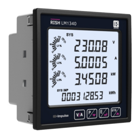
1. INTRODUCTION The Multifunction Instrument is a panel mounted 96 x 96mm DIN Quadratic Digital Panel Meter, which measures important electrical parameters in 3 ph 4 wire / 3 wire / 1ph Network and replaces the multiple analog panel meters. It measures electrical parameters like AC voltage, Current, Frequency, Power, Energy (Active / Reactive / Apparent), phase angle, power factor, individual harmonics &... -
Page 8: Measurement And Energy/Counter Screens
2. MEASUREMENT AND ENERGY/COUNTER SCREENS In normal operation, the user is presented with two simultaneous screens: 1. One of the Measurement screens out of the screens of Table 1.1 / 1.3 / 1.4 . These screens may be scrolled through one at a time in an incremental order by pressing the respective key. Few important screens are explained in Section 2.1 to 2.7. - Page 9 RS485 Connection Indication It indicates that the serial communication between the instrument and the computer / control / automation system is activated through the RS485 output of the instrument by glowing continuously. In case the communication is not active, the indication is not shown. Digital Input Indication The Digital Input (DI) symbols indicate the following : 1.
- Page 10 TABLE 1 : Measurement & Energy/Counter Screens Table 1.1 System Parameters Screens : Parameter On Modbus On Display Parameters 3P 4W 3P 3W 1P 2W 3P 4W 3P 3W 1P 2W System Voltage/ Current/ Active Power ...
- Page 11 Table 1.1 System Parameters Screens Continued... Parameter On Modbus On Display Parameters 3P 4W 3P 3W 1P 2W 3P 4W 3P 3W 1P 2W System Voltage Unbalance System Current Unbalance ...
- Page 12 Table 1.2 Energy Parameters Screens Continued... Parameter On Modbus On Display Parameters 3P 4W 3P 3W 1P 2W 3P 4W 3P 3W 1P 2W Run hour On hour ...
- Page 13 Table 1.2 Energy Parameters Screens Continued... Parameter On Modbus On Display Parameters 3P 4W 3P 3W 1P 2W 3P 4W 3P 3W 1P 2W Old L1-L2-L3 Active Energy Import(Overflow) ...
- Page 14 Table 1.3 Power Parameters Screens : On Modbus On Display Parameter Parameters 3P 4W 3P 3W 1P 2W 3P 4W 3P 3W 1P 2W L1 VA-VAr-Watt L2 VA-VAr-Watt ...
- Page 15 Table 1.4 Voltage/Current Parameters Screens : On Modbus On Display Parameter Parameters 3P 4W 3P 3W 1P 2W 3P 4W 3P 3W 1P 2W L1-L2-L3 Voltage L12-L23-L31 Voltage ...
-
Page 16: Current Reversal Screen
2.1 Current Reversal Screen This screen is one of the Voltage / Current Parameter Screens and is useful to indicate if current in any phase is reversed or not. If current in any phase gets reversed, then corresponding phase will be indicated on this screen. -
Page 17: Phase Absent Screen
2.3 Phase Absent Screen This screen is one of the Voltage / Current Parameter Screens and is useful to indicate if voltage or current in any phase is absent. Hence, user will know which voltage or current is missing and take corrective action. XX XX XX XX XX XX... - Page 18 2.5.1. Health Monitor Fault Screens XX XX XX XX XX XX XX XX XX XX XX XX XX XX XX XX XX XX This screen indicates that current This screen indicates that phase This screen indicates that voltage unbalanced fault is present. fail fault is present.
-
Page 19: Pre-Paid Energy Menu
2.6 Pre Paid Energy Menu This screen is one of the System Parameter Screens. XX XX XX XX XX XX XX XX XX XX XX XX XX XX XX XX XX XX Pre Paid Menu shows Balance This Screen shows the Balance This Screen shows Balance energy &... -
Page 20: Timer 1 & Timer 2 Screens
2.7 Timer 1 & Timer 2 Screens This screen is one of the System Parameter Screens. No. of Cycles = 10 ON Delay = 12 sec OFF Delay = 5 sec Relay 1 in Timer mode XX XX XX XX The screen shows the No. -
Page 21: Run Hour
Similarly, for Timer Configuration, Relay 2 parameters and status can also be set and accessed (respectively) in a way similar to that of Relay 1. 2.8 Run Hour This Screen is one of the Energy Parameter screens and shows the total no. - Page 22 Setup Parameter Screens CodE (PassWord ) SEL (Select) HL Mn dGiP PArA SYS PArA rESEt Ser PArA Out PArA (Digital Input (Health Monitor) (System Parameter) (Serial Comm.Parameter) (Reset Parameter) (Output Parameter) Parameter) (Sec 3.2.6) (Sec 3.2.1) (Sec 3.2.2) (Sec 3.2.4) (Sec 3.2.5) (Sec 3.2.7) dEV Addr...
- Page 23 Setup Parameter Screens FACt rESEt quit tAriF PArA DiSP PArA (Quit Setup Menu) (Taariff Parameter) (Display Parameter) (Factory Reset Para) (Sec 3.2.9) (Sec 3.2.10) (Sec 3.2.11) (Sec 3.2.8) bcLit PArA No oF tArif (Backlit Parameter) (Number of Tariff) Exit From Setup (Sec 3.2.9.1) (Sec 3.2.8.1) Parameter...
- Page 24 Output Options Parameters nonE PuLSE out LiMit out tiMEr HELtH Mntr PrEPd EnrGy (No Output) (Pulse Output) (Limit Output) (Timer) (Health Monitor) (Pre-Paid Enregy) (Sec 3.2.5.1.1.0) (Sec 3.2.5.1.1.1) (Sec 3.2.5.1.1.2) (Sec 3.2.5.1.1.3) (Sec 3.2.5.1.1.4) (Sec 3.2.5.1.1.5) LiM-N PArA PArA SEL CycLE PArA SEL ConF SEL...
-
Page 25: Programming
3. PROGRAMMING The following sections comprise step by step procedures for configuring the Multifunction Meter according to individual user requirements.To access the set-up screens press and hold “ UP ” and “ DOWN ” keys simultaneously for 5 seconds. This will take the User into the Password Protection Entry Stage (Section 3.1). 3.1. - Page 26 Enter Password, second digit entered, prompt for third digit. Press the “ ” key to scroll the value of first digit from 0 through to 9, the value rolls back from 9 round to 0 and “ ” key to scroll the value of first digit from 9 through to 0, the value rolls back from 0 round to 9.
- Page 27 Password Incorrect. The unit has not accepted the Password entered. Pressing the “ ” or “ ” key advances to the Enter Password stage. Pressing the “ ” key exits the Password menu & returns operation to the measurement reading mode. New / Change Password Prompting for first digit.
-
Page 28: Menu Selection
New/ Change Password, third digit entered, prompting for fourth digit. . Press the “ ” and “ ” keys to scroll the value of second digit from 0 through to 9 and from 9 through to 0,respectively with digit roll around feature. -
Page 29: Communication Parameter Selection
3.2.2 Communication Parameter Selection This screen is used to select the different communication parameters like “Address selection”,“RS485 Parity selection”, “RS485 baud rate”, etc. Pressing the “ ” key allows the user to set different Communication parameters (see Section 3.2.2.1 to 3.2.2.3). Pressing the “... - Page 30 3.2.5 Output Option Selection This screen will allow the user to select Output Options like “Relay Output”. Pressing the “ ” key allows the user to select and configure the output options (see Section 3.2.5.1). Pressing “ ” key advances to the “Load Health Parameters Selection” screen (see section 3.2.6) and pressing “...
- Page 31 3.2.8 Tariff Parameter Selection This screen will allow the user to select Tariff Parameter options like configuring the 6 tariff energies, No. of tariff, Tariff Mode. Pressing the “ ” key allows the user to select and configure the parameter options.(see Section 3.2.8.1 to Section 3.2.8.3) Pressing the “...
-
Page 32: System Type
3.2.1 System Parameter Selection 3.2.1.1 System Type This screen is used to set the system type. Pressing the “ ” key advances into the system type edit mode and pressing the “ ” and “ ” key scrolls through the options available: System type “3P3W”... - Page 33 Potential Transformer Primary Decimal Point Edit (Flashing decimal point indicates the cursor position).Initially the “decimal point must be selected, pressing the “ ” or “ ” key moves the decimal point position to the right until it disappears, which means that it has reached # # # #.
-
Page 34: Potential Transformer Secondary Value
3.2.1.3 Potential Transformer Secondary Value The value must be set to the nominal full scale secondary voltage which will be obtained from the Transformer when the potential transformer (PT) primary is supplied with the voltage defined in 3.2.1.2 Potential Transformer Primary voltage.The ratio of full scale primary to full scale secondary is defined as the transformer ratio.The PT Secondary value can be set from 100VL-L to 600VL-L (according to input voltage range). -
Page 35: Current Transformer Primary Value
3.2.1.4 Current Transformer Primary Value The nominal Full Scale Current that will be displayed as the Line currents. This screen enables the user to display the Line currents inclusive of any transformer ratios, the values displayed represent the Current in Amps. -
Page 36: Current Transformer Secondary Value
3.2.1.5 Current Transformer Secondary Value This screen is used to set the secondary value for Current Transformer. Secondary value “5” for 5A or “1” for 1A can be selected. Pressing the “ ” key accepts the present value and advances to the “System Frequency”... -
Page 37: Demand Integration Time
3.2.1.7 Demand Integration Time This screen is used to set the period over which current and power readings are to be integrated. The Unit of displayed value is minutes. Pressing the “ ” key enables editing and pressing keys “ ”... -
Page 38: Of Poles
Pressing the “ ” key confirms the selection and advances to “Low Current Noise Cutoff” screen (see Section 3.2.1.9). NOTE: Default value is set as ‘0’ mA. 3.2.1.10 No. of Poles This screen enables to set No. of poles of a Generator of which RPM is to be measured and to which the instrument is connected to monitor its parameters. -
Page 39: Energy Digit Reset Count
NOTE: 1. Default value is set to ‘2’ i.e. Energy will be in terms of kWh/kVArh/kVAh respectively. 2. If (PT primary(VLL) * CT primary * Root3) >30000 kW, then Energy Output can be set only as kWh and MWh. 3. Energy on display is auto-ranging & so this setting is only applicable for modbus energy counters. (For Energy auto-ranging refer Section 4.1.) 3.2.1.12 Energy Digit Reset Count This screen enables user for setting maximum energy count after which... -
Page 40: Impulse Rate
Pressing the “ ” key advances to the Energy Rate edit mode. Pressing “ ” and “ ” scrolls the count in minutes from 1 to 60 and from 60 to 1, respectively. Ex. If Energy Rate is set to 2 then energy will get stored after 2 minutes on the modbus. -
Page 41: Address Setting
3.2.1.16 Quit System Parameters This screen allows user to Exit from System Parameter selection setup. Pressing the “ ” key advances to “System Type” screen (see Section 3.2.1.1). Similarly, pressing the “ ” key advances to “Version Information” screen (see Section 3.2.1.15). Pressing the “ ”... -
Page 42: Rs 485 Baud Rate
3.2.2.2 RS 485 Baud Rate This screen allows the user to set Baud Rate of RS 485 port. The values displayed on screen are in kbaud. Pressing “ ” key accepts the present value and advance to the “RS 485 Parity Selection”... -
Page 43: Ip Parameter Selection
3.2.3 IP Parameter Selection 3.2.3.1 IP Address Setting This screen allows the user to set Ip address. Pressing “ ” key accepts the present value and advance to the “Quit Ip parameters” screen (see Section 3.2.3.5) and pressing the “ ”... -
Page 44: Default Gateway Setting
Edit mode Pressing the “ ” or “ ” key scrolls the value of the most significant digit from 0 through 9 or 9 through 0, respectively Pressing the “ ” key accepts the present value at the cursor position and advances the cursor to the next less significant digit. -
Page 45: Server Port Setting
3.2.3.4 Server Port Settings This screen allows the user to set Server Port for the meter. The allowable range of addresses is 001 to 999. Press “ ” key to advance to “Default Gateway” screen (see Section 3.2.3.3) or press the “ ”... -
Page 46: Reset Parameter Selection
3.2.4 Reset Parameter Selection 3.2.4.1 Resetting Parameter This screen allows the users to reset Energy, Low(Min), high(Max), Demand, Run hour, On hour, No. of Interrupts, Tariff, Digital Input External Energy. Reset Parameters Reset (None) Pressing “ ” key advances to “Reset Parameters” screen. Pressing the “... -
Page 47: Output Option Selection
3.2.5. Output Option Selection This screen applies to the relay output option selection. Pressing “ ” key advances to “Relay Selection” menu (see Section 3.2.5.1). 3.2.5.1 Relay Selection Pressing “ ” and “ ” keys scrolls through the following screens: rEL1 : To select options for relay 1 (See section 3.2.5.1.1). -
Page 48: Pulse Output
3.2.5.1.1.1 Pulse Output This screen is used to set the pulse output parameter. Pressing “ ” key advances to “Parameter Selection” screen (see Section 3.2.5.1.1.1.1) whereas pressing “ ” key advances to “Quit Pulse Output” menu (see Section 3.2.5.1.1.1.4). XX XX XX XX 3.2.5.1.1.2 Limit Output This screen is used to assign Relay in Limit output mode. - Page 49 3.2.5.1.1.4 Load Health Monitor Output This screen is used to assign Relay in Load Health Monitor output mode. Pressing “ ” key advances to “Load Health Monitor Configuration” menu (see Section 3.2.5.1.1.4.1) whereas pressing “ ” key advances to “Quit Load Health Output”...
-
Page 50: Parameter Selection
3.2.5.1.1.1.1 Parameter Selection This screen allows the user to assign energy for pulse output. Pressing “ ” key accepts the present setting and advance to “Pulse duration selection” (see section 3.2.5.1.1.1.2) and pressing “ ” key accepts the present setting and advance to “Quit Relay Output” selection (see section 3.2.5.1.1.1.4). -
Page 51: Pulse Rate
3.2.5.1.1.1.3 Pulse Rate This screen applies to the Pulse Output option only. The screen allows user to set the Energy Pulse Rate divisor. Divisor values can be selected through 1,10,100,1000 as per Energy Unit (refer Section 3.2.1.11) set. Refer TABLE 2.2 “Energy Pulse Rate Divisor” for details. Pressing “... -
Page 52: Limit Output Parameters
3.2.5.1.1.2.1 Limit Output Parameters This screen is for Limit output mode selection. It allows the user to set Limit output corresponding measured value. Refer TABLE 3 “Parameter for Limit output” for assignment. Pressing “ ” key accepts the present parameter and for energy parameters 37 to 41 and 200 to 232 as present value, advances to the “Energy Trip Point”... -
Page 53: Trip Point
3.2.5.1.1.2.3 Trip Point This screen applies to Trip point selection for parameters other than 37 to 41 & 200 to 232 (Refer TABLE 3) selected in Section 3.2.5.1.1.2.1. This screen allows the user to set Trip point for selected limit relay. The allowable range is 10% to 120% for High Alarm, 10% to 100% for Low Alarm (refer TABLE 3). -
Page 54: Energy Trip Point
3.2.5.1.1.2.5 Energy Trip Point This screen applies to the Energy Trip point selection for parameters 37 to 41 and 200 to 232 (Refer TABLE 3) selected in Section 3.2.5.1.1.2.1. This screen is used to trip the relay using the energy count. The relay trips after the lapse of “ON Delay”... -
Page 55: Logic Operation Selection
3.2.5.1.1.2.6 Logic Operation Selection This screen is used to perform the logical operation between the three limit parameters. i.e. Limit - 1, Limit - 2 and Limit - 3. User can perform any of the following operations using this screen : 1) None (To trip the relay based on only one limit parameter) 2) AND (To trip the relay when all the three limit parameters conditions are satisfied) -
Page 56: Relay Configuration
3.2.5.1.1.2.7 Relay Configuration This screen is used to select one of the two configurations of relay for the selected limit output parameter. (see Section 3.2.5.1.1.2.1) Pressing the “ ” key accepts the present selection and advances to the “ON Delay” screen (see section 3.2.5.1.1.2.8) and pressing the “ ”... -
Page 57: Limit Output Off Delay
ON Delay Edit Mode Press “ ” key, prompt for the first digit. Press the “ ” and “ ” keys to scroll the values of the first digit. Press the “ ” key to advance to next digit. Similarly, enter second, third and fourth digits also. After the fourth digit is entered, pressing “... -
Page 58: Quit Limit Output
3.2.5.1.1.2.10 Quit Limit Output The screen allows user to exit the Relay output selection menu. Pressing “ ” key advances to “Limit Output” menu (See section 3.2.5.1.1.2) and pressing “ ” key advances to “Limit Output OFF Delay” menu (see Section 3.2.5.1.1.2.9). Pressing “... -
Page 59: Timer Configuration
3.2.5.1.1.3.2 Timer Configuration The option decides the relay configuration for timer output. Two options are available: 1. EnrG : Energize on start 2. d-Enr : De-energize on start. Pressing “ ” key confirms the selection and advances to the “On Delay” menu (See section 3.2.5.1.1.3.3) and pressing “... - Page 60 ON Delay Edit Mode Press the “ ” key to advance to next digit. Similarly, enter second, third and fourth digits also. After the fourth digit is entered, pressing “ ” key sets the value and advances to “On Delay” screen (see Section 3.2.5.1.1.3.3). The value for this parameter can range from 0001 to 9999 seconds.
- Page 61 3.2.5.1.1.3.5 Quit Timer Output The screen allows user to exit the Timer output menu. Pressing “ ” key advances to the “Timer Output” menu (see Section 3.2.5.1.1.3) and pressing “ ” key advances to “Off Delay” menu (see Section 3.2.5.1.1.3.4). Pressing “...
- Page 62 3.2.5.1.1.5.1 Parameter Selection This screen allows user to assign energy parameters as per TABLE - 2.1 for Pre-Paid Energy output. Pressing “ ” key accepts the present setting and advance to “Unit Cost ” (see section 3.2.5.1.1.5.2) selection & pressing “...
- Page 63 Unit Cost Edit mode (Flashing decimal point indicates the cursor position).Initially the decimal point must be selected, pressing the “ ” or “ ” key moves the decimal point position to the right until it disappears, which means that it has reached # # # #.
- Page 64 Topup Recharge Edit mode Pressing the “ ” key advances to the first digit position. Press the “ ” and “ ” keys to scroll the values of the first digit Press the “ ” key to advance to next digit. Similarly, enter second, third until seventh digit.
- Page 65 3.2.5.1.1.5.5 Quit Pre Paid Energy Output The screen allows user to exit the Pre Paid Energy output menu. Pressing “ ” key advances to the “Pre Paid Energy Output” menu (see Section 3.2.5.1.1.5) and pressing “ ” key advances to “New Recharge” menu (see Section 3.2.5.1.1.5.4).
- Page 66 3.2.6.2 Unbalance Current Limit This screen allows the user to set Trip point for instrument, when the Current is unbalance. Pressing “ ” key accept the present value and advances to “Under Frequency limit” screen (see Section 3.2.6.3). Pressing “ ”...
- Page 67 Edit mode (Flashing decimal point indicates the cursor position). Initially the decimal point must be selected, pressing the “ ” or “ ” key moves the decimal point position to the right & left respectively until it disappears, which means that it has reached # # # #. after which it returns to #. # # # or # # #. Pressing the “...
- Page 68 3.2.6.5 Over Voltage Limit This screen allows the user to set Trip point for instruments when the voltage is above the tripping point. Pressing “ ” key accept the present value and advances to “Over current limit” screen (see Section 3.2.6.6). Pressing “ ”...
- Page 69 Edit mode (Flashing decimal point indicates the cursor position). Initially the decimal point must be selected, pressing the “ ” or “ ” key moves the decimal point position to the right & left respectively until it disappears, which means that it has reached # # # #. after which it returns to #. # # # or # # #. Pressing the “...
- Page 70 Edit mode Pressing the “ ” key promts for the first digit. Pressing the “ ” and “ ” keys scroll the values of the first digit. Similarly , enter second, third and fourth digits also. After the fourth digit is entered, pressing “ ”...
- Page 71 3.2.7.3 Digital Input 1 Pulse Multiplier The screen allows user to set the values of the Digital Input 1 Pulse Multiplier. Pressing “ ” key advances to the “Digital Input 2 Mode Selection” (see Section 3.2.7.4) and pressing “ ” key advances to the “Digital Input 2 Mode Selection”...
- Page 72 Edit mode Pressing the “ ” and “ ” keys lets the user scroll through the available options. Pressing the “ ” key confirms the selection and takes the user to the Digital Input 2 Mode Selection Menu.(see Section 3.2.7.4) Note : Default configuration is set to “status”...
- Page 73 3.2.7.6 Quit Digital Input Pressing the “ ” key takes the user out of the Digital Input Selection Screen and advances to the Digital Input Menu. (see Section 3.2.7) Pressing “ ” key advances to the “De-bounce Time” Selection Screen (see Section 3.2.7.1) and pressing “...
- Page 74 3.2.8.2 Tariff Mode Selection This screen allows the user to select the available tariff modes. 1)Modbus 2)Digital Input * Pressing the “ ” key advances to “Tariff Energies Selection” screen (see Section 3.2.8.3) and pressing the “ ” key advances to “Number of Tariff Selection”...
- Page 75 3.2.8.4 Quit Tariff Parameters Pressing “ ” key advances to the “Number of Tariff” Selection Screen (see Section 3.2.8.1) and pressing “ ” key advances to the “Tariff Energy Selection” screen (see Section 3.2.8.3). Pressing the “ ” key takes the user out of the Tariff Parameters Selection Screen and advances to the Tariff Parameter Menu Screen.
- Page 76 Backlit Edit Mode In Edit Mode, pressing “ ” and “ ” keys allows the user to scroll between On/OFF and pressing “ ” key confirms the selection. Pressing “ ” key again advances to editing mode whereas pressing “ ”...
- Page 77 User Screen Edit Mode Pressing “ ” key sets the selected value and advances to “Screen Number Selection” screen (see Section 3.2.9.1.2.1). Note: 1.The value 0 should be chosen if the user wants all the screens to be shown. 2. If User Screen feature is ON and System type is changed, then the Userscreen is disabled.
- Page 78 3.2.9.1.2.3 Quit Userscreens This screen is used to exit User defined Screen selection. Pressing the “ ” key advances to the “User Assignable Screens” menu (see Section 3.2.9.1.2). 3.2.9.1.3 Contrast This screen allows the user to set the contrast for the display. Pressing the “...
- Page 79 3.2.9.1.4 Display Test Screen This screen allows the user to check if there is any fault in one of the symbols or segments on the LCD display by completely turning on the display. Pressing “ ” and “ ” key advances to Quit Screen (see Section 3.2.9.5) and Contrast Screen (see Section 3.2.9.3) respectively.
- Page 80 3.2.10.1 Factory Reset Selection This screen allows the user to erase all data from the meter and set all setup parameters to their default values. Pressing the “ ” key advances to the “Sure” (confirmation) screen which displays a “no”. Pressing “...
- Page 81 4. Energy Auto-Ranging On Display : 4.1 Calculating Display energy (Auto-ranging): In case of energy auto-ranging the energy shown on modbus will be in terms of Overflow count (OF) & main energy counter (M) based on energy unit/resolution & energy digit reset count (EDRC). So energy on modbus will have unit set in energy resolution on modbus (ie.
- Page 82 Example for Calculating Display Energy from modbus Energy Counters: Energy unit/resolution on modbus register 46021 is set to 2 (ie. It will measure energy in kWh). Overflow count (OF) value on modbus register 30109 for watt Import is 25. Energy main counter (M) value on modbus register 30111 for watt import is 2587413.189 Energy digit reset count (EDRC) set by user in modbus register 46023 is 8.
- Page 83 4.2 Entering Energy start count: Applicable for meter with modbus or Ethernet) Energy start count is the feature that allows user to set count from which the meter should start incrementing energy. The start count can be set for main energy start counter & Overflow energy start Counter separately from modbus or Ethernet.
- Page 84 5. Relay Output (Optional) : The Meter is provided with relay for pulse output, limit switch, Load health tripping, Pre-Paid Energy based tripping and as a Timer. 5.1 Pulse Output : Pulse Output is the potential free, very fast acting relay contact which can be used to drive an external mechanical counter for energy measurement.
- Page 85 TABLE 2.1 : Continued... Parameter Parameter 3P4W 3P 3W 1P 2W Number Total Sys Apparent Energy Total Active Energy L1 Total Active Energy L2 Total Active Energy L3 ...
- Page 86 5.2 Limit Switch : Limit switch can be used to monitor upto three measured parameter (refer TABLE 3) with either ANDing/ORing or no logic for tripping in relation with to a set limit. The limit switch can be configured for Alarm-High or Alarm-Low, settable for each parameter and Energized or de- Energized for the relay.
-
Page 87: On Delay
Note : In case of Alarm - Low if trip point is set greater than 80% then the maximum hysteresis can be set such that the total Trip point+ Hysteresis(% of trip point value) will not exceed 120% of range. For example :If trip point is set at 90%, then maximum 33.3% hysteresis should be set such that, [90 + 29.99 (33.3% of 90)] = 120. - Page 88 TABLE 3 : Parameters for Limit output Trip Point 100% Parameter Parameter Set Range Value Number None Vnom (L-N) Volts 1 10 - 120 % Vnom (L-N) Volts 2 10 - 120 % ...
- Page 89 TABLE 3 : Continued... Trip Point 100% Parameter Parameter Set Range Value Number Wh Export 10 - 9999999 VArh Capacitive 10 - 9999999 VArh Inductive 10 - 9999999 10 - 9999999 ...
- Page 90 TABLE 3 : Continued... Trip Point 100% Parameter Parameter Set Range Value Number Distortion VAr L2 10 - 120 % Distortion VAr L3 10 - 120 % SUM Distortion VAr 10 - 120 % ...
- Page 91 TABLE 3 : Continued... Trip Point 100% Parameter Parameter Set Range Value Number Total Active Energy L1 10-9999999 Total Active Energy L2 10-9999999 Total Active Energy L3 10-9999999 Total Reactive Energy L1 10-9999999 ...
-
Page 92: Timer Output
5.3 Timer Output Timer output can be used to operate the Relay in a cyclic manner. The user can define the ON period and OFF period and also the number of times this cycle is to be repeated. The number of Cycles (N) can be indefinite or 1 to 9999. The counting is shown on a measurement screen as explained before. -
Page 93: Phasor Diagram
6. Phasor Diagram : Capacitive Inductive Capacitive Inductive Sign of Sign of Sign of Inductive / Connections Quadrant Active Reactive Power Capacitive Power ( P ) Power ( Q ) Factor ( PF ) Import Import Export Export Inductive means Current lags Voltage Capacitive means Current leads Voltage When Multifunction Meter displays When Multifunction Meter displays... -
Page 94: Installation
7. Installation Mounting of the Meter is featured with easy “Clip- in” mounting. Push the meter in panel slot (size 92 x92 mm), it will click fit into panel with the four integral retention clips on two sides of meter. If required, additional support is provided with swivel screws as shown in figure. -
Page 95: Case Dimensions And Panel Cut-Out
The Current inputs of these products are designed for connection in to systems via Current Transformers only, where one side is grounded. 4. ESD precautions must be taken at all times when handling this product. 7.2 Case Dimensions and Panel Cut-Out 53mm 92mm+0.8 96mm... -
Page 96: Wiring
7.3 Wiring Input connections are made directly to screw-type terminals with indirect wire pressure. Numbering is clearly marked on the connector. Choice of cable should meet local regulations. Terminal for both Current and Voltage inputs will accept upto 4mm (12AWG) solid or 2.5 mm stranded cable. : It is recommended to use wire with lug for connection with meter. -
Page 97: Connection Diagrams
8. Connection Diagrams 3-PHASE 4-WIRE UNBALANCED LOAD 3-PHASE 3-WIRE UNBALANCED LOAD DIGITAL METERING SYSTEM (WITH EXTERNAL AUX.) DIGITAL METERING SYSTEM (WITH EXTERNAL AUX.) 13 14 2 5 8 11 1 3 4 6 7 9 2 5 8 SUPPLY SUPPLY SINGLE PHASE 2-WIRE DIGITAL METERING SYSTEM (WITH EXTERNAL AUX.) 13 14... -
Page 98: Optional Pluggable Module
9. Optional Pluggable Module Optional Pluggable Module... -
Page 99: Specification
10. Specification System 3 Phase 3 Wire / 4 Wire or Single Phase programmable on site Inputs 100VLL to 600VLL programmable on site. Nominal Input Voltage Vn (AC RMS) (57.5VLN to 346.42VLN) System PT Primary Values 100VLL to 1200 kVLL, programmable on site System PT Secondary Values 100VLL to 600VLL programmable on site. - Page 100 Auxiliary Supply External Higher Aux. 100V to 550V AC-DC Ext. High Aux. (As per IEC 61557-12) 100V to 320V AC-DC External Higher Aux. Nominal Value 230V AC/DC, 50/60 Hz for AC Aux External Lower Aux. 12V to 60V AC-DC External Lower Aux. Nominal Value 24 V AC / 48 V DC, 50/60 Hz for AC Aux Aux Frequency Range 45 to 66 Hz...
- Page 101 Accuracy Voltage + 0.5% (0.2% optional) of nominal value + 0.5% (0.2% optional) of nominal value Current Frequency + 0.1 % of mid frequency + 0.5% (0.2% optional) of nominal value Active power Reactive power + 1.0% of nominal value Apparent Power + 0.5% (0.2% optional) of nominal value Power Factor / Phase Angle...
- Page 102 Isolation Protective Class High Voltage Test Input+Aux vs Surface 4 kV RMS, 50Hz, 1 min Input/Aux vs Remaining Circuit 3.3 kV RMS, 50Hz, 1 min DI/Relay/RS485/USB vs Remaining 3.3 kV RMS, 50Hz, 1 min DI vs DI/Relay vs Relay 2.2 kV RMS, 50Hz, 1 min Impulse Voltage Withstand 5kV for 1.2uSec Environmental conditions...
- Page 103 Panel thickness 1 - 3mm for self clicking 1 - 6mm for swivel screws Weight 320 grams Approx. Interfaces Impulse Led For Energy testing Digital Input (optional) 20...300 VAC / 10...60 VDC Optical Couplers, Min Pulse width 10msec Min length between two pulses 18msec VA Consumption : <...
- Page 104 mpulse Constant Depending on nominal system nominal power, the number of impulses are created to measure the energy.The number of impulses for particular nominal power is set which indicates 1kWh energy.Energy can be Watt,VA or Var.Following table shows impulses corresponding to nominal system energy.
- Page 105 11. Connection for Optional Pulse Output / Digital Input / RS 485 / Ethernet Module (rear (back) view of Multifunction Meter): Location of Modbus, 2 Relay Location of Ethernet & 2 Digital Inputs VL1 VL2 VL3 VL2 VL1 VL2 VL3 VL2 ADDON MODULE ADDON MODULE 1.Down Side...
Need help?
Do you have a question about the RISH LM 1340 and is the answer not in the manual?
Questions and answers