
Related Manuals for Polimaster PM 2012M

Summary of Contents for Polimaster PM 2012M
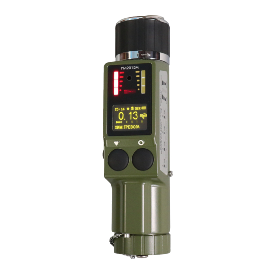
- Page 1 COMBINED CHEMICAL AGENT AND GAMMA RADIATION DETECTOR PM2012M Models PM 2012M PM 2012MA PM 2012MВ Operation Manual...
- Page 2 No liability for Consequential Damage In no event shall Polimaster Ltd., any of its affiliates, or anyone involved in the creation, production, or delivery of the accompanying product (including hardware and software) be liable for any loss of profits or any special, incidental, consequential, exemplary, or other damages...
- Page 3 HazMat operations, emergency and first response services. If any assistance is needed or problems arise, please contact your local Polimaster Ltd. representative or Polimaster Ltd. directly:...
- Page 4 LIMITED WARRANTY Manufacturer warrants to the purchaser (the “Purchaser”) that the Product, including component parts, is free from material defects in material and workmanship, under normal use and service for a period of 1 (one) year (the “Warranty Period”) provided, however, that the foregoing warranties are expressly contingent (and shall otherwise be void) upon use of the Products in accordance with specifications and without misuse, abuse, or abnormal use, accident, damage, alteration, or modification thereto or improper or unauthorized repairs or improper maintenance.
- Page 5 EXCLUSIONS OF DAMAGES AND LIABILITY PURCHASER ASSUMES THE ENTIRE COST OF ANY DAMAGE RESULTING FROM THE USE OF THE PRODUCT AND THE INFORMATION CONTAINED IN, GATHERED OR COMPILED BY THE PRODUCT, AND THE INTERACTION (OR FAILURE TO INTERACT PROPERLY) WITH ANY OTHER HARDWARE OR SOFTWARE WHETHER PROVIDED BY MANUFACTURER OR A THIRD PARTY.
-
Page 6: Table Of Contents
Contents Chapter 1: Safety and Regulations Requirements ..............7 1.1 Safety symbols ........................... 7 1.2 General radiation safety ......................7 1.2.1 Radioactive source information ..................7 1.3 Storage ............................7 1.4 Shipping ............................. 7 1.5 Disposal ............................. 8 1.6 Emergency response ........................8 Chapter 2: System overview ...................... -
Page 7: Chapter 1: Safety And Regulations Requirements
Chapter 1: Safety and Regulations Requirements This document gives guidance regarding the safe and proper use of sealed radioactive devices. It is important that the information therein is followed at all times. Relevant national regulations, codes of practice, and transport regulations must be applied, where they exist. 1.1 Safety symbols Safety information contained in this manual is separated from the text and marked with an appropriate symbol to indicate the type of danger. -
Page 8: Disposal
1.5 Disposal Please follow the national regulations for the disposal of instruments with sealed radioactive sources. 1.6 Emergency response WARNING! • When a radioactive source or/and chemical weapon agent vapors are detected the appropriate national regulations should be strictly observed. •... -
Page 9: Chapter 2: System Overview
Chapter 2: System overview 2.1 Main Features The PM 2012M/PM2012MA are simply-to-operate and reliable instruments in shockproof cases. The two control buttons are of big size to allow the operator to use protective gloves. • Η The instruments measure the ambient dose equivalent rate and the ambient dose equivalent Н*(10) of gamma- and X-ray radiation. -
Page 10: Technical Specifications
2.2 Technical Specifications Feature Description Detector of gamma and X-ray radiation Geiger-Mueller counter Detector of vapors of chemical warfare agents Ionization chamber with beta source Ni-63, ~ 600 MBq (16 mCi) Measurement range of the dose equivalent rate from 1 µSv/h to 10 Sv/h Indication range of the dose equivalent rate from 0.01 µSv/h to 13 Sv/h Main relative dose rate measurement error:... - Page 11 LEDs bar Instrument case protection class IP55 Communication with PC IR link, IrDA standard USB channel (for PM2012MB) Weight no more 0.77 kg no more 66х47х195 mm Dimensions Ask the manufacturer for any additional information or visit www.polimaster.com.
-
Page 12: Kit Components
2.3 Kit Components The instrument comes with the following components: GP Alkaline LR20 size D Battery The PM2012M / PM2012MA / PM2012MB Measuring cup CWA simulator Fabric filter elements № 1 and 2 (white) Fabric filter element (black) Bottle with filter filler Cleaning rod Screw key Piece of cotton cloth... - Page 13 OPTIONAL ACCESSORIES 220V/12V AC adapter and 9-36 V DC power cable Rotameter USB cable (for PM2012MB) Infrared adapter (ACT-IR220L or IR-210B)
-
Page 14: Instrument Design
2.4 Instrument Design The instrument is a monoblock, which encloses two independent modules: - gamma-radiation detector module (Radiation Detector Module) containing a Geiger- Mueller counter; - chemical warfare detector module (CWA Module) including an ionizing chamber with Ni-63 beta source, and a micro pump. The unit contains also appropriate electronics (with a nonvolatile memory) that controls over the unit operation and stores the operation history. -
Page 15: Principles Of Operation
The sequent push of the “MODE” button switches between the following instrument’s modes: Dose equivalent rate measurement of gamma and X-ray radiation; Dose equivalent measurement of gamma and X-ray radiation; PC and smartphone (only for PM2012MB) communication mode; Clock-Calendar mode. The sequent push of the “SET”... -
Page 16: Chapter 3: Preoperational Procedures
Chapter 3: Preoperational Procedures 3.1 Battery installation The unit comes without battery installed. CAUTION! Install and replace the battery when the CWA module is switched off! (refer to section 3.3.) To install the battery unscrew the lid of the battery compartment (10) (Figure 2.1), insert the battery observing its polarity (the "+"... -
Page 17: Ac Adapter And Dc Power Supply
3.2 AC adapter and DC power supply The unit can be also operated using the AC adapter. Open a rubber cap protecting the port (9) (Figure 2.1) and connect the adapter with the adapter jack. AC adapter Input: 190-264 V, 1.1 A; Output: 12 V, 14.5W;... - Page 18 Test screen Dose rate screen Figure 3.3 – Test and dose rate screens The display also shows: the unit name (PM2012M), firmware version (v.07), serial number of the unit (SN: 00150003), time (11:36) and the dose rate statistical error (99%). Test screen is displayed after the battery is installed.
-
Page 19: Checking Instrument Operation And Functionality
3.4 Checking instrument operation and functionality Before operating the instrument, it is advisable to perform the procedures described below. 3.4.1 Checking the Radiation Detector Module To check the operation and functionality of the Radiation Detector module, turn on the instrument; after the tests are completed, place a gamma source of 50 - 200 kBq activity (energy range of 0.06 - 3.0 MeV) near the gamma detector geometrical center marked on the left side of the instrument (Figure 3.5). - Page 20 The calibration continues about 2 min, and then the unit displays “CHEM: SEARCH ON”. It means that the calibration is completed and the instrument is ready to detect the CWA. Figure 3.7 – Calibration completion screen If the calibration fails during about 2 min due to a high CWA concentration or a high pollution of the ionization chamber, the instrument automatically enters the ionization chamber blowing mode and displays “CHEM: BLOWING”.
- Page 21 If the instrument is switched to the CWA detection mode while the calibration procedure is not completed, the unit displays "CHEM: CALIBRATION ON". Please switch the unit to the calibration mode (refer to section 3.4.2.1). Place the CWA simulator (included with the unit, refer to section 2.3) near the inlet (1) (Figure 2.3) of the instrument and open it.
-
Page 22: Chapter 4: Operation Guidelines
Chapter 4: Operation Guidelines 4.1 Introduction While the unit is turned on and the self-tests are successfully completed (section 3.3), the instrument starts continuous measurements of the dose equivalent and dose equivalent rate of gamma and X-ray radiation, and the dose accumulation time independently on the operating mode of the CWA module and the screens displayed (except the PC communication mode, refer to section 4.4). -
Page 23: Dose Rate Measurements
4.2 Dose rate measurements The unit displays the dose rate values in "µSv/h, "mSv/h", and "Sv/h" (or "µR/h, "mR/h", and "R/h"). As the dose rate increases, the instrument switches these measurement units automatically. The statistical error of the measured dose rate value is shown in the upper right corner of the display in percents with 0.95 probability. -
Page 24: Dose Measurements
4.3 Dose measurements The unit displays the dose equivalent values in "µSv", "mSv", and "Sv" (or "µR", "mR", and "R"). As the dose increases, the instrument switches these measurement units automatically. The measured dose equivalent value is displayed graphically as well on the analogue scale. The number of lighting segments of the analogue scale corresponds to the dose equivalent value relative to the preset threshold. -
Page 25: Detection Of The Chemical Warfare Agents
"PM2012M Data Processing Software" (on memory drive included with the instrument) enables the operator to change the dose measurement units from Sv to R and vice versa, to set a DE threshold, and to reset the dose and dose accumulation time values. The event of the dose value resetting and the reset dose value are stored in the instrument’s memory. - Page 26 Each LED bar represents the analogue scale with three segments corresponding to the CWA relative concentrations. Table 4.1– Red and yellow LEDs bars indicating the detected CWA concentrations Combinations of analogue scale segments blinking during the CWA detection Approximate relative CWA Audible alarm Arsenic Organopho-...
-
Page 27: Pc Communication Mode
4.5 PC communication mode The PC communication mode disables any other instrument operating mode. The factory instrument settings are as follow: • time intervals for recording the current dose equivalent values into the 60 min instrument non-volatile memory • threshold value of the dose equivalent rate 1 µSv/h •... - Page 28 The instrument communication with PC is described in details in the "PM2012_Software Guide" file, installed on PC together with software. To switch the PC communication mode off, press the SET button. PM2012M Data Processing Software and PM2012MB Data processing Software enable the operator: 1) to change operational parameters of the connected instrument: •...
-
Page 29: Pc Communication Via Usb (For Pm2012Mb)
4.5.1 PC communication via USB (for PM2012MB) The instruments provide data exchange with PC running WINDOWS OS via USB interface. The instruments connection to PC is performed with the use of USB cable (included in the delivery kit) to the USB port embedded in PC. To connect the instrument to PC special software “PM2012MB Data Processing Software”... -
Page 30: Chapter 5: Preventive Maintenance
Chapter 5: Preventive Maintenance This section includes routine preventive maintenance procedures for the PM2012M. Failure to perform preventive maintenance can cause severe malfunctions, resulting in non- warranty unit restoration repairs. THE MAINTENANCE KIT IS INCLUDED WITH THE INSTRUMENT. CAUTION! Only properly trained and skilled personnel can perform the maintenance procedures. -
Page 31: Cleaning The Gas Lines And Ionization Chamber
5.2 Cleaning the gas lines and ionization chamber CAUTION! Make sure that the alcohol drops and cotton cloth fibers are not left in the ionization chamber and inlet after the cleaning procedure. 5.2.1 Cleaning the vapor inlet The cleaning procedure consists of the following steps: •... -
Page 32: Cleaning The Ionization Chamber
5.2.2 Cleaning the ionization chamber • insert the cleaning rod with cloth wetted with rectified ethanol through the cleaned inlet into the ionization chamber cavity until stop; • wipe the inner surface of the ionization chamber with circular motions; • repeat these steps 2-3 times with a new cloth; •... -
Page 33: Gas Lines Blowing
5.2.4 Gas lines blowing Blow gas lines after their cleaning (section 5.2). To blow gas lines switch the instrument into the CWA module calibration mode and leave it in this mode for about an hour. The instrument can produce false chemical alarms. Switch the CWA module off in an hour. 5.3 Test of the micropump capacity Connect the lower silicone tube of the rotameter (available as an option) with the outlet (11) (Figure 3.2), check that a seal is made tight. -
Page 34: Replacement Of The Filter Elements
5.4 Replacement of the filter elements The filter construction is shown in Figure 5.1. 1 nut; 7 gauze; 2 ring; 8 gauze; 9 fabric filter element № 1 (white) (included in 3 nut; 4 spring; the Accessories kit); 10 fabric filter element № 2 (white) (included in 5 ring;... - Page 35 • remove: spring (4), ring (5), fabric filter element (6) (replace it with the new one from the Accessories kit), and gauze (7) (blow the gauze through); • pour the coal out; • remove the gauze (8) and blow it through, remove the fabric filter elements (9) and (10);...
-
Page 36: Radioactive Source Replacement
Figure 5.2 – Coal level inside the unit case 5.5 Radioactive source replacement WARNING! The beta-source should be replaced with a new one when its lifetime specified in the certificate (Appendix A) is expired. This procedure should be fulfilled by the specially trained personnel at the manufacturer facility or authorized service center. -
Page 37: Chapter 6: Troubleshooting Guide
Chapter 6: Troubleshooting Guide This section lists common fault symptoms and corresponding troubleshooting procedures. Fault symptom Possible reason Troubleshooting procedure (s) Instrument doesn’t turn on Battery is dead, misplaced Replace, or insert the battery or there is no battery at all correctly.
Need help?
Do you have a question about the PM 2012M and is the answer not in the manual?
Questions and answers