Table of Contents
Advertisement
Available languages
Available languages
Quick Links
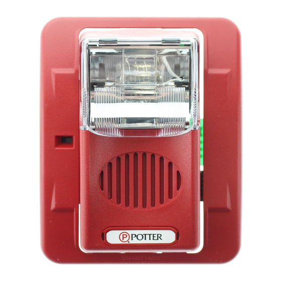
VISIBLE AND/OR AUDIBLE
SIGNALING APPLIANCES
ADDITIONAL CAN/ULC LISTED PRODUCT INFORMATION IS FOUND ON PAGES 5 AND 6
I. INTRODUCTION
The Potter Electric models HS24-177, S24-177, EH-24, HS-24, S-24, HS-24-WP, HSLP-24-WP, S-24-WP, SLP-24-WP, CHS-24A, CS-24WA, CHS-24B, CS-24WB, CHS-24G, CS-24WG,
CHS-24R, CS-24WR, CHS-24A-WP, CHSLP-24A-WP, CS-24WA-WP, CSLP-24WA-WP, CHS-24B-WP, CHSLP-24B-WP, CS-24WB-WP, CSLP-24WB-WP, CHS-24G-WP, CHSLP-24G-WP,
CS-24WG-WP, CSLP-24WG-WP, CHS-24R-WP, CHSLP-24R-WP, CS-24WR-WP, CSLP-24WR-WP are high quality audible and/or visible signaling appliances. The high intensity strobe utilizes
a Xenon flash tube that generates a high-intensity flash visible from all angles. This appliance is intended to provide a visible, audible or audible/visible, depending on the model, notification
signal for the purpose of life safety and property protection. The HS-24, S-24, CHS-24A, CS-24WA, CHS-24B, CS-24WB, CHS-24G, CS-24WG, CHS-24R, CS-24WR are provided with a slider
switch which allows for candela selection at the installation site; the candela intensities which can be selected are 15Cd, 30Cd, 60Cd, 75Cd, or 110Cd. The HS24-177 and S24-177 are fixed
candela units; the candela intensity which can be ordered is 177Cd. The HS-24-WP, HSLP-24-WP, S-24-WP, SLP-24-WP, CHS-24A-WP, CHSLP-24A-WP, CS-24WA-WP, CSLP-24WA-WP,
CHS-24B-WP, CHSLP-24B-WP, CS-24WB-WP, CSLP-24WB-WP, CHS-24G-WP, CHSLP-24G-WP, CS-24WG-WP, CSLP-24WG-WP, CHS-24R-WP, CHSLP-24R-WP, CS-24WR-WP,
CSLP-24WR-WP are fixed candela units, available in a 75 candela intensity only. This appliance is ideal for any occupancy that requires notification appliances per the applicable building or fire
code or wherever dependable alarms are required.
The HS24-177, S24-177, HS-24, S-24 strobe is listed in compliance with ANSI/UL 1971, Signaling Appliances for the Hearing Impaired. The HS-24-WP, HSLP-24-WP, S-24-WP, SLP-24-WP,
CHS-24A, CS-24WA, CHS-24B, CS-24WB, CHS-24G, CS-24WG, CHS-24R, CS-24WR, CHS-24A-WP, CHSLP-24A-WP, CS-24WA-WP, CSLP-24WA-WP, CHS-24B-WP, CHSLP-24B-WP,
CS-24WB-WP, CSLP-24WB-WP, CHS-24G-WP, CHSLP-24G-WP, CS-24WG-WP, CSLP-24WG-WP, CHS-24R-WP, CHSLP-24R-WP, CS-24WR-WP, CSLP-24WR-WP strobe is listed in
compliance with ANSI/UL 1638, Visual Signaling Appliances - Private Mode Emergency and General Signaling. Additionally, colored lens models CHS-24A, CS-24WA, CHS-24B, CS-24WB,
CHS-24G, CS-24WG, CHS-24R, CS-24WR comply with the polar dispersion requirements of ANSI/UL 1971.
II. LOCATION
This appliance is intended for use in Fire Alarm Systems and is to be installed in accordance with this manual, the recommendation of the local authorities having jurisdiction, and other NFPA
documents that provide standards on notification appliances for protective signaling systems. The HS24-177, S24-177, EH-24, HS-24, S-24, CHS-24A, CS-24WA, CHS-24B, CS-24WB,
CHS-24G, CS-24WG, CHS-24R, CS-24WR are intended for indoor installations only; this appliance is not listed for outdoor or drip proof applications. The HS-24-WP, HSLP-24-WP, S-24-WP,
SLP-24-WP, CHS-24A-WP, CHSLP-24A-WP, CS-24WA-WP, CSLP-24WA-WP, CHS-24B-WP, CHSLP-24B-WP, CS-24WB-WP, CSLP-24WB-WP, CHS-24G-WP, CHSLP-24G-WP, CS-24WG-WP,
CSLP-24WG-WP, CHS-24R-WP, CHSLP-24R-WP, CS-24WR-WP, CSLP-24WR-WP are intended for indoor or outdoor installations; this appliance is rated for outdoor or drip proof applications
when used in conjunction with the WPBB or WPLPBB Enclosure.
Wall mounted strobe and horn/strobe appliances shall have their entire lens at heights above the finished floor of not less than 80 in. (2m) and not greater than 96 in. (2.4m)**. Spacing shall be
in accordance with Table A. If a room configuration is not square, the room size that will entirely encompass the room or subdivide the room into multiple squares shall be used. Wall mounted
horn only appliances shall have their tops above the finished floors at heights of not less than 90 in. (2.30m) and below the finished ceilings at heights of not less than 6 in. (152mm). Different
mounting heights shall be permitted by the AHJ provided the sound pressure level requirements of NFPA 72 are met.
III. MOUNTING, ROUGH-IN BOX AND RUN WIRING
This unit is designed for mounting to most single gang boxes, 4" square outlet boxes, 2-gang masonry boxes or non-metallic 2-gang switch boxes. Conduit entrance to boxes should be
selected to insure sufficient wiring clearance.
1. Run a minimum 18 gauge insulated 2 or more conductor cable.
2. Mount a box for each remote signaling appliance. Screw bracket onto box. Insert signal into bracket and slide to the right firmly into the terminal block
receptacle. Place housing over mounted assembly and screw together with single screw at the bottom of the signal. Cover screw with plastic tab.
NOTICE: WIRING SHOULD BE CONNECTED TO MOUNTING BRACKET PRIOR TO MOUNTING SIGNAL. INCOMING POSITIVE POWER LEAD MUST BE BROKEN AND EACH LEAD IS
TO BE INSERTED INTO EACH OF THE TOP TWO TERMINALS. IF TWO POWER RUNS ARE MADE TO THE SIGNAL, ONE FOR THE STROBE AND ONE FOR THE HORN, ONLY ONE OF
THE RUNS MUST HAVE ITS POSITIVE LEAD BROKEN AND PLACED UNDER THE TWO SEPARATE TOP TERMINALS. A BARRIER IS PROVIDED TO PREVENT BOTH LEADS FROM
BEING PLACED UNDER THE SAME TERMINAL.
Room Spacing for Wall-Mounted Visible Appliances per NFPA 72, 2013 Edition
Table A
Maximum Room Size
Meters
6.10 x 6.10
8.53 x 8.53
9.14 x 9.14
12.2 x 12.2
13.7 x 13.7
15.2 x 15.2
16.5 x 16.5
16.8 x 16.8
18.3 x 18.3
19.2 x 19.2
20.7 x 20.7
21.3 x 21.3
24.4 x 24.4
27.4 x 27.4
30.5 x 30.5
33.5 x 33.5
36.6 x 36.6
NA = Not allowable
39.6 x 39.6
HS24-177, S24-177, HS-24 AND S-24 PRODUCT INFORMATION
Minimum Required Light Output ( Effective Intensity, Cd)
One Light
Feet
per Room
20 x 20
15
28 x 28
30
30 x 30
34
40 x 40
60
45 x 45
75
50 x 50
94
54 x 54
110
55 x 55
115
60 x 60
135
63 x 63
150
68 x 68
177
70 x 70
184
80 x 80
240
90 x 90
304
100 x 100
375
110 x 110
455
120 x 120
540
130 x 130
635
firealarmresources.com
HS24-177, S24-177, EH-24, HS-24 & S-24 SERIES
ANSI/UL & CAN/ULC COMPLIANT
HS-24-WP, HSLP-24-WP, S-24-WP & SLP-24-WP SERIES
CHS-24A, CS-24WA, CHS-24B, CS-24WB, CHS-24G,
CS-24WG, CHS-24R & CS-24WR SERIES
CHS-24A-WP, CHSLP-24A-WP, CS-24WA-WP, CSLP-24WA-WP
CHS-24B-WP, CHSLP-24B-WP, CS-24WB-WP, CSLP-24WB-WP
CHS-24G-WP, CHSLP-24G-WP, CS-24WG-WP, CSLP-24WG-WP
CHS-24R-WP, CHSLP-24R-WP, CS-24WR-WP & CSLP-24WR-WP SERIES
ANSI/UL & CAN/ULC COMPLIANT
Four Lights per Room
(One Light per Wall)
NA
NA
NA
15
19
30
**Effective Intensity Requirements for Sleeping Areas
30
30
30
Distance from Ceiling to Top of Lens
37
greater than or equal to 24"
43
less than 24"
60
60
CAUTION:
95
Strobe light must be
95
installed within 16 feet
135
of the pillow when used
135
in a sleeping area.
185
Visible Notification Appliance
Intensity
110cd
177cd
550-0593
Page 1
Advertisement
Table of Contents

Related Manuals for Gentex HS24-177 Series


Summary of Contents for Gentex HS24-177 Series
- Page 1 HS24-177, S24-177, EH-24, HS-24 & S-24 SERIES ANSI/UL & CAN/ULC COMPLIANT HS-24-WP, HSLP-24-WP, S-24-WP & SLP-24-WP SERIES CHS-24A, CS-24WA, CHS-24B, CS-24WB, CHS-24G, CS-24WG, CHS-24R & CS-24WR SERIES CHS-24A-WP, CHSLP-24A-WP, CS-24WA-WP, CSLP-24WA-WP VISIBLE AND/OR AUDIBLE CHS-24B-WP, CHSLP-24B-WP, CS-24WB-WP, CSLP-24WB-WP CHS-24G-WP, CHSLP-24G-WP, CS-24WG-WP, CSLP-24WG-WP SIGNALING APPLIANCES CHS-24R-WP, CHSLP-24R-WP, CS-24WR-WP &...
- Page 2 Strobe light cannot be seen when objects such as doors, furniture or walls block strobe light. NOTICE: w THE VISUAL SIGNAL MUST BE IN THE DIRECT VIEWING AREA OF THE OCCUPANT IN ORDER TO BE SEEN. w VISUAL SIGNALS FOR THE HEARING IMPAIRED ARE ONLY ONE METHOD OF ALERTING THE HEARING IMPAIRED. VISUAL SIGNALS MAY NOT BE THE PREFERRED METHOD FOR NOTIFYING ALL HEARING IMPAIRED INDIVIDUALS.
- Page 3 IV. WIRING Wiring for synchronized strobes and horns. Using this method you may: Use only two wires to synchronize the temporal horn and strobe with the ability to mute the horn (place switches 1 and 2 in the ON position on the HS24-177, HS-24, HS-24-WP, HSLP-24-WP, CHS-24A, CHS-24B, CHS-24G, CHS-24R, CHS-24A-WP, CHSLP-24A-WP, CHS-24B-WP, CHSLP-24B-WP, CHS-24G-WP, CHSLP-24G-WP, CHS-24R-WP, CHSLP-24R-WP).
-
Page 4: Checkout And Troubleshooting
Candela selection slider switch. Depress To remove bezel, grip both center and slide switch to sides of bezel and pull in a desired brightness level. downward and outward motion. Break off pin and insert into hole at the bottom of the selector to lock candela setting. -
Page 5: Product Information
ADDITIONAL INSTRUCTIONS FOR VISIBLE AND/OR AUDIBLE SIGNALING APPLIANCES: CAN/ULC PRODUCT INFORMATION This appliance is intended to provide a visible, audible or audible/visible, depending on the model, notification signal for the purpose of life safety and property protection. This appliance is ideal for any occupancy that requires notification appliances per the applicable building or fire code or wherever dependable alarms are required. -
Page 6: Limited Warranty
CAN/ULC HORN DECIBEL AND CURRENT RATINGS PRODUCT INFORMATION: OUTDOOR HORN & HORN/STROBE REFER TO CAN/ULC HORN CURRENT CHART ON PAGE 5 FOR CAN/ULC HORN CURRENT RATINGS FOR OUTDOOR HORN AND HORN/STROBE PRODUCTS HORN DECIBEL RATINGS IN ULC ANECHOIC ROOM (dBA @ 3 meters) OUTDOOR HORN AND HORN/STROBE Regulated 24 VDC... - Page 7 SÉRIES HS24-177, S24-177, EH-24, HS-24 ET S-24 CONFORME AUX NORMES ANSI/UL ET CAN/ULC SÉRIES HS-24-WP, HSLP-24-WP, S-24-WP ET SLP-24-WP SÉRIES CHS-24A, CS-24WA, CHS-24B, CS-24WB, CHS-24G, CS-24WG, CHS-24R ET CS-24WR APPAREILS DE SIGNALISATION SÉRIES CHS-24A-WP, CHSLP-24A-WP, CS-24WA-WP, VISUELLE OU SONORE CSLP-24WA-WP, CHS-24B-WP, CHSLP-24B-WP, CS-24WB-WP, CSLP-24WB-WP CHS-24G-WP, CHSLP-24G-WP, CS-24WG-WP, CSLP-24WG-WP, CHS-24R-WP, CHSLP-24R-WP, CS-24WR-WP ET CSLP-24WR-WP CONFORME AUX NORMES ANSI/UL ET CAN/ULC...
-
Page 8: Renseignements Sur Le Produit
Il n’est pas possible de voir le stroboscope lorsqu’il est masqué par un objet, notamment une porte, un meuble ou un mur. AVIS : w POUR ÊTRE APERÇU, L’APPAREIL DE SIGNALISATION VISUELLE DOIT ÊTRE DANS LA ZONE DIRECTE DE VISUALISATION DE L’OCCUPANT. w AVIS : LES APPAREILS DE SIGNALISATION VISUELLE NE SONT QU’UNE DES MÉTHODES POUR ALERTER LES PERSONNES AYANT UNE DÉFICIENCE AUDITIVE. - Page 9 IV. CÂBLAGE Câblage pour la synchronisation du stroboscope et de l’avertisseur. Avec cette méthode, vous pouvez : DISTANCE (TENSION AU PANNEAU/TENSION MIN. DE L’APPAREIL) CONDUCTIVITE DES FILES MAX. DE FIL w Utiliser seulement deux fils pour synchroniser l’avertisseur temporel et le stroboscope, tout en ayant la possibilité de couper l’avertisseur APPEL DE COURANT TOTAL (EN PIEDS) (placer les commutateurs 1 et 2 en position «...
- Page 10 Commutateur à glissière de sélection de l’intensité lumineuse. Appuyer au centre Pour retirer le cadre, du commutateur et le faire agripper les deux côtés glisser pour obtenir l’intensité et tirer vers le bas et souhaitée. l’extérieur. Briser la tige et l’insérer dans le trou au bas du sélecteur pour sélectionner l’intensité...
- Page 11 DIRECTIVES SUPPLÉMENTAIRES POUR LES APPAREILS DE SIGNALISATION APPAREILS DE SIGNALISATION : CAN/ULC RENSEIGNEMENTS SUR LE PRODUIT L’appareil est conçu pour émettre, selon le modèle, un signal d’avertissement visuel, sonore ou sonore et visuel pour assurer la sécurité des personnes et la protection matérielle. Cet appareil convient parfaitement à...
-
Page 12: Garantie Limitée
RENSEIGNEMENTS CAN/ULC SUR LE PRODUIT – CARACTÉRISTIQUES NOMINALES D’INTENSITÉ ACOUSTIQUE ET DE COURANT AVERTISSEUR ET AVERTISSEUR STROBOSCOPE SE REPORTER AU TABLEAU CAN/ULC DES COURANTS DE L’AVERTISSEUR POUR LES CARACTÉRISTIQUES NOMINALES DE COURANT CAN/ULC POUR UN AVERTISSEUR ET UN AVERTISSEUR STROBOSCOPE EXTÉRIEUR CARACTÉRISTIQUES SONORES NOMINALES EN DÉCIBELS DANS UNE CHAMBRE ANÉCHOÏQUE ULC (dBA à...
Need help?
Do you have a question about the HS24-177 Series and is the answer not in the manual?
Questions and answers