Table of Contents
Advertisement
Quick Links
Advertisement
Table of Contents

Related Manuals for Planet Networking & Communication LN501


Summary of Contents for Planet Networking & Communication LN501
- Page 1 LoRa Node Controller LN501 and LN1152 LoRa Node Controller LN501 and LN1152 - 1 -...
- Page 2 LoRa Node Controller LN501 and LN1152 Copyright Copyright (C) 2022 PLANET Technology Corp. All rights reserved. The products and programs described in this User’s Manual are licensed products of PLANET Technology, This User’s Manual contains proprietary information protected by copyright, and this User’s Manual and all accompanying hardware, software, and documentation are copyrighted.
- Page 3 In most, if not all cases, these designations are claimed as trademarks or registered trademarks by their respective companies. Revision User’s Manual of PLANET LoRa Node Controller Model: LN501 and LN1152 Rev.: 1.0 (April, 2022) Part No. EM-LN501_LN1152_v1.0 - 3 -...
-
Page 4: Table Of Contents
LoRa Node Controller LN501 and LN1152 Table of Contents Chapter 1. Product Introduction ..................... 5 Package Contents ...................... 6 Overview ........................7 Features ........................8 Product Specifications ....................9 Chapter 2. Hardware Introduction ..................11 Physical Descriptions ....................11 Hardware Installation ....................14 Chapter 3. -
Page 5: Chapter 1. Product Introduction
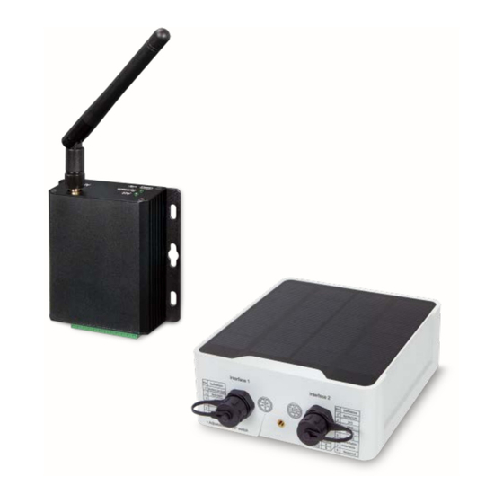
LoRa Node Controller LN501 and LN1152 Chapter 1. Product Introduction Thank you for purchasing PLANET LoRa Node Controller, LN series. The descriptions of these models are as follows: LN501 Outdoor IP67 LoRa Node Controller with Solar Panel LN1152 Indoor IP30 LoRa Node Controller “LoRa Node”... -
Page 6: Package Contents
LoRa Node Controller LN501 and LN1152 1.1 Package Contents The package should contain the following: LN501 LN1152 LoRa Node Controller x 1 LoRa Node Controller x 1 Quick Installation Guide x 1 Quick Installation Guide x 1 ... -
Page 7: Overview
LoRaWAN networks. LN501: It can be easily and quickly configured by NFC or wired USB port. For outdoor applications, it provides solar or built-in battery power supply and is equipped with IP67-rated enclosure and M12 connectors to protect itself from water and dust in harsh environments. -
Page 8: Features
LoRa Node Controller LN501 and LN1152 1.3 Features Key Features LN501 • Easy to connect with multiple wired sensors through GPIO/AI/RS232/RS485 interfaces • Long transmission distance up to 11km with line of sight • Waterproof design including IP67 case and M12 connectors •... -
Page 9: Product Specifications
LN501 and LN1152 1.4 Product Specifications Product LN501 Wireless Transmission Technology LoRaWAN LN501-868M: IN865, EU868, RU864 Frequency LN501-915M: US915, AU915, KR920, AS923 Tx Power 16dBm(868)/20dBm(915) Sensitivity -137dBm @300bps Work Mode Class A, Class C Data Interfaces Interface Type M12 A-Coded Male Ports 2 ×... - Page 10 LoRa Node Controller LN501 and LN1152 Product LN1152 Wireless Transmission Technology LoRaWAN Antenna × 50 Ω SMA Connectors (Center Pin: SMA Female) Connector LN1152-868: IN865, EU868, RU864 Frequency LN1152-915: US915, AU915, KR920, AS923 Tx Power 16dBm(868)/20dBm(915) Sensitivity -147dBm @300bps Work Mode...
-
Page 11: Chapter 2. Hardware Introduction
LoRa Node Controller LN501 and LN1152 Chapter 2. Hardware Introduction 2.1 Physical Descriptions LN501 DIP Switch: Interface DIP Switch 12V: 1 on 2 off 3 off (default) Power Output 9V: 1 off 2 on 3 off 5V: 1 off 2 off 3 on... - Page 12 LoRa Node Controller LN501 and LN1152 Power Button: Function Action LED Indication Off → On Turn On Press and hold the button for more than 3s. On → Off Turn Off Press and hold the button for more than 3s.
- Page 13 LoRa Node Controller LN501 and LN1152 LN1152 Definition Description Ground 5-24 V DC RS232 RS485 IN_COM OUT_COM OUT_NC OUT_NO LED Definition Indication Status Description Static System Start-up System On for 500 ms, off for 500 ms The system is running properly.
-
Page 14: Hardware Installation
LoRa Node Controller LN501 and LN1152 2.2 Hardware Installation Refer to the illustration and follow the simple steps below to quickly install your LoRa Node. 2.2.1 LoRa Antenna Installation (LN1152) Step 1: Rotate the antenna into the antenna connector accordingly. - Page 15 LoRa Node Controller LN501 and LN1152 LN1152 Step 1: Align the LN1152 device horizontally to the desired position on the wall and use a marker pen to mark two mounting holes on the wall. Step 2: Drill the two holes marked previously on the wall by using your drill with a 6 mm drill bit.
- Page 16 LoRa Node Controller LN501 and LN1152 2.2.3 Application Wiring Digital Input: Digital Output: Analog Input: RS232 & RS485: - 16 -...
- Page 17 LoRa Node Controller LN501 and LN1152 LN1152 series supports 5-24 V DC power supply. You can use other supplies or power adapter to power on the device. For industrial applications, it’s suggested not to release the metal case and use an independent power supply.
-
Page 18: Chapter 3. Preparation
Before accessing the LoRa node controllers, user has to install utility tool for operation. 3.1 Requirements • Workstations running Windows 10/XP/2003/Vista/7/8/2008. • Type C USB cable for LN501 • Micro USB cable for LN1152 3.2 Managing LoRa Node Download ToolBox software from Planet web site. -
Page 19: Chapter 4. Operations Management
LoRa Node Controller LN501 and LN1152 Chapter 4. Operations Management This chapter provides operations details of the LoRa node controller. 4.1 Managing LoRa Node Download ToolBox software from Planet web site. https://www.planet.com.tw/en/support/downloads?&method=keyword&keyword=LN501&view=6#list Power on the LoRa Node device and then connect it to computer via micro USB port. - Page 20 LoRa Node Controller LN501 and LN1152 After logging in the ToolBox, you can click “Power On” or “Power Off” to turn on/off device and change other settings. - 20 -...
-
Page 21: Lorawan Setting
Default App EUI is 24E124C0002A0001. Application Port The port is used for sending and receiving data; default port is Note: RS232 data will be transmitted via another port. LN501: Class A and Class C are available; Working Mode LN1152: Class C. Join Type... - Page 22 LoRa Node Controller LN501 and LN1152 5572404C696E6B4C6F52613230313823. Device Address DevAddr for ABP mode, default is the 5th to 12th digits of SN. Nwkskey for ABP mode, default is Network Session 5572404C696E6B4C6F52613230313823. Appskey for ABP mode, default is Application Session Key 5572404C696E6B4C6F52613230313823.
- Page 23 LoRa Node Controller LN501 and LN1152 If frequency is one of AU915/US915, you can enter the index of the channel that you want to enable in the input box, making them separate by commas. Examples: 1, 40: Enabling Channel 1 and Channel 40...
-
Page 24: Interface Setting
LoRa Node Controller LN501 and LN1152 4.3 Interface setting LN501 and LN1152 support data collection by multiple interfaces including GPIOs, analog inputs and serial ports. Besides, they can also power the terminal devices by power output interfaces. Basic settings are as follows: Go to “General ->... -
Page 25: Rs485 Settings
LN501 and LN1152 4.3.1 RS485 Settings 1. Connect RS485 device to RS485 port on interface 2. If you need LN501 to power the RS485 device, please connect the power cable of RS485 device to 5V/9V/12V power output on interface 2. - Page 26 The execution interval between Modbus commands. Max. Response Time The maximum response time that the LN501 waits for the reply to the command. If it does not get a response after the maximum response time, it is determined that the command has timed out.
- Page 27 01 03 00 00 00 01 84 0A 4. For ToolBox software, click “Fetch” to check if LN501 can read correct data from terminal devices. You can also click “Fetch” on the top of list to fetch all channel data.
-
Page 28: Rs232 Settings
LN501 and LN1152 4.3.2 RS232 Settings 1. Connect RS232 device to RS232 port on interface 2. If you need LN501 to power the RS232 device, connect the power cable of RS232 device to 5V/9V/12V power output on interface 1. 2. Go to “General -> Serial” of ToolBox software to enable RS232 and configure serial port settings. -
Page 29: Gpio Settings
LoRa Node Controller LN501 and LN1152 4.3.3 GPIO Settings 1. Connect devices to GPIO ports on interface 2. 2. Go to “General -> GPIO” of ToolBox software to enable GPIO port. 3. Select GPIO type according to your requirements. ... - Page 30 After selection, click “Fetch” to check current status of digital input. Digital Output: Click “Switch” to check if LN501 can trigger devices by digital output or click “Fetch” to check the current status of digital output. - 30 -...
-
Page 31: Ai Settings
Count the value from 0. 4.3.4 AI Settings 1. Connect analog device to analog input ports on interface 1. If you need LN501 to power the analog device, connect the power cable of analog device to 5V/9V/12V power output on interface 1. - Page 32 4. Enable “Interface 1 (Pin 1) 5V/9V/12V” and configure “Power Output Time Before Collect”, LN501 will power the analog devices for a period of time before collecting data. When you use power output to power analog devices, it only supplies power when reporting interval is coming.
-
Page 33: Maintenance
You can also click “Up to Date” to search for the latest firmware of the device and upgrade. 4.4.2 Backup LN501 devices support configuration backup for easy and quick device configuration in bulk. Backup is allowed only for devices with the same model and LoRa frequency band. Please select one of following methods to back up device: 1. -
Page 34: Reset To Factory Default
4.4.3 Reset to Factory Default Please select one of following methods to reset device: Hardware: Open the case of LN501 and hold on power button for more than 10s. ToolBox Software: Go to “Maintenance -> Backup and Reset” to click “Reset”.
Need help?
Do you have a question about the LN501 and is the answer not in the manual?
Questions and answers